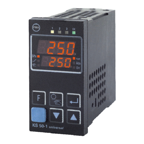
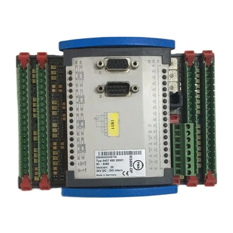
PMA KS800 Operating and installation instructions


©PMA Prozeß- und Maschinen-Automation GmbH. Printed in Germany
All rights reserved. No part of this document may be
reproduced or published in any form or by any means without prior written permission
by the copyright owner.
A publication of PMA Prozeß- und Maschinen-Automation GmbH
Subject to change without notice
PMA Prozeß- und Maschinen-Automation GmbH
P.O. Box 31 02 29
D 34058 Kassel
Germany
Restriction of warranty:
No warranty is given for the complete correctness of this manual, since errors can never avoided
completely despite utmost care. Any hints are welcome and gratefully accepted.

Multi-Temperature-Controller KS 800
Contents
1 Introduction ..................................................... 7
1.1 Basic structure .............................................. 7
1.2 Input ...................................................... 7
1.3 Functions .................................................. 8
1.4 Output .................................................... 8
2 Input signal processing ............................................ 9
2.1 Measurement value pre-processing ............................... 9
2.2 Measuring frequency .......................................... 9
2.3 Sensor types ................................................ 9
2.3.1 Thermocouples ......................................... 9
2.3.2 Resistance thermometer ................................. 10
2.3.3 Resistance ........................................... 10
2.3.4 DC voltage ........................................... 10
2.4 Measurement value correction .................................. 11
2.4.1 Application examples ................................... 12
2.5 Digital input signal pre-processing ............................... 12
2.5.1 Input signal distribution .................................. 12
2.5.2 Analog input signals .................................... 12
2.5.3 Digital input signals ..................................... 13
3 Controller block diagram .......................................... 14
3.1 Sequence control ........................................... 14
4 Set-point functions ............................................... 15
4.1 Set-point control ............................................ 15
5 Function block protocol .......................................... 16
5.1 Data structure ............................................. 16
5.2 Structure of configuration words ................................. 17
5.2.1 Function block instrument ............................... 17
6 Controller statuses and status priorities .............................. 21
6.1 Priority 0 automatic ......................................... 21
6.2 Priority 1 Tune, run ......................................... 21
6.3 Priority 2 Tune, error ........................................ 22
6.4 Priority 3 Sensor break ....................................... 22
6.5 Priority 5 Manual ........................................... 22
6.6 Priority 7 Y_Track .......................................... 23
6.7 Priority 8 Controller off ....................................... 23
7 Automatic - manual switch-over ..................................... 24
8 Self-tuning for single-loop controllers ................................ 25
8.1 Preparation for controller self-tuning: ............................. 25
8.1.1 Process at rest ........................................ 25
8.1.2 Selecting the stable correcting variable ...................... 25
8.1.3 Start from automatic mode ............................... 26
8.1.4 Start from manual mode ................................. 26
8.2 Self-tuning procedure with heating (2-point and three-point stepping
controller) ................................................ 26
8.3 Self-tuning procedure with heating and cooling processes: (3-point
controller) ................................................. 26
8.4 Set-point monitoring ......................................... 27
9499 040 49211 3

Multi-Temperature-Controller KS 800
8.5 Self-tuning several controllers in a group .......................... 27
8.5.1 Starting the group self-tuning .............................. 27
8.5.2 Group self-tuning stop ................................... 27
8.5.3 Common start of the heating attempt for all controllers of a group . . . 27
8.5.4 Common start of the cooling attempt for all 3-point heating/cooling
controllers ........................................... 28
8.5.5 Signification of self-tuning messages ....................... 28
9 Controlled adaptation ............................................. 29
9.1 Control function parameters .................................... 30
10 Signaller ....................................................... 31
11 Two-point controller .............................................. 32
12 Three-point DPID controller ........................................ 34
13 Three-point stepping controller ..................................... 36
14 Forcing of switching outputs ....................................... 39
15 Continuous controllers ........................................... 40
16 Water cooling ................................................... 42
16.1 Water cooling controller self-tuning ............................... 44
17 Cascade control ................................................. 45
17.1 Configuration of a simple cascade ............................... 45
17.2 Controller behaviour with switch-over ............................. 46
17.2.1 Master controller switch-over from .......................... 46
17.2.2 Slave controller switch-over : .............................. 46
17.3 Interruption of cascade operation ................................ 46
17.4 Example of cascade control with up to 7 slave controllers .............. 47
18 Start-up circuit .................................................. 49
19 Mean value formation for the output hold function ...................... 51
20 Heating current monitoring ........................................ 52
20.1 Heating current monitoring ..................................... 52
20.2 Monitoring cycle ............................................ 52
20.2.1 Heating current alarm, reset and quick test ................... 53
21 Evaluation of heating current measurement ........................... 54
21.1 Leakage current monitoring .................................... 54
21.2 Heating current scaling factor ................................... 55
22 Alarm handling .................................................. 56
23 Configuration ................................................... 58
23.1 General .................................................. 58
23.2 Main configuration groups ..................................... 58
23.2.1 C100 main controller configuration .......................... 58
23.2.1.1 C101 additional controller configuration ........... 59
23.2.2 Control loop monitoring (loop alarm) ........................ 60
23.2.3 C150 Heating current and output monitoring .................. 61
23.2.3.1 C151 additional heating current configuration ....... 62
49499 040 49211

Multi-Temperature-Controller KS 800
23.2.4 C180 analog signal allocation ............................. 62
23.2.5 C190 digital signal allocation .............................. 63
23.3 Inputs .................................................... 64
23.3.1 C200 main configuration ................................. 64
23.3.2 Input scaling .......................................... 65
23.3.2.1 C201 input scaling start ....................... 65
23.3.2.2 C202 input scaling end ....................... 65
23.3.3 C205 additional configuration ............................. 66
23.3.3.1 C210 external temperature compensation .......... 66
23.3.3.2 C213 sensor failure .......................... 67
23.3.3.3 C214 filter time constant ...................... 67
23.4 Configuration examples ....................................... 68
23.4.1 Thermocouples ........................................ 68
23.4.2 Resistance thermometer ................................. 68
23.4.3 Voltage ............................................. 68
23.4.4 C302 heating current input ............................... 68
23.5 Outputs ................................................... 69
23.5.1 C500 signal inputs/outputs ............................... 69
23.5.2 Alarm outputs ......................................... 70
23.5.2.1 Action C530 ............................... 70
23.5.3 Analog outputs ....................................... 71
23.5.3.1 C600, C602, C603, C604 type of alarms .......... 72
23.5.3.2 C601 alarm target ........................... 73
23.5.4 C700 controller self-tuning ............................... 74
23.5.5 Additional functions ..................................... 75
23.5.5.1 C900 Baud rate COM1 PC interface .............. 75
23.5.5.2 C901 COM1 address ......................... 75
23.5.6 COM2 interface ....................................... 76
23.5.6.1 C902 Baud rate COM2 bus interface ............. 77
23.5.6.2 C903 COM2 address ......................... 77
23.5.7 C904 mains frequency, alarm and current output configuration ..... 78
24 Special functions ................................................ 79
24.1 Selective mean value formation ................................. 79
24.1.1 Configuration ......................................... 81
24.2 Safety limiter with holding function ............................... 82
9499 040 49211 5

Multi-Temperature-Controller KS 800
69499 040 49211

Multi-Temperature-Controller KS 800
1 Introduction
The functions of multiple controller KS 800 are described in this document. Not all functions are
applicable to all versions, since some hardware and software functions are mutually precluding
due to the controller configuration (e.g. 8-channel three-point stepping controller and digital in-
puts).
1.1 Basic structure
The basic KS 800 structure for control function handling is shown below. The unit is divided into
four main groups:
input
functions
output
user interface
(The user interface function is not described in this manual.)
User Interface
Interface Signals
Input Output
Functions
Meas. value
aquisition
Signal pre-processing
Signal distribution
Alarm processing
Controller functions
Closed loop
control
Signal output
Signal post-processing
Sequence control
Signals
from the
field
Signals
to the
field.
Set-point
processing
Operating and
display Diagnosis and
production
Interface selection
1.2 Input
Measurement value acquisition
The input signals from the field are acquisitioned and converted according to adjusted sensor
type.
Measurement value correction
This block is used for measurement value corrections (zero offset, suppression, gain adjustment).
9499 040 49211 7

Multi-Temperature-Controller KS 800
Signal distribution
The conditioned input signals are passed to the controller cyclically (together with the relevant
control parameters).
1.3 Functions
Sequence control
The sequence control describes the statuses and priorities in the control algorithm and the condi-
tions and signals for other function statuses.
Closed-loop control
The correcting variable is calculated dependent of selected controller configuration and adjusted
control parameters.
Set-point processing
Dependent of controller configuration, various functions for generation of the valid (effective) set-
point (Weff) are selected for the control functions.
Alarm processing
Each individual controller has different alarm functions, each with four trigger points. The alarms
can be allocated to various alarm functions by configuration.
1.4 Output
Signal post-processing
The controller calculation result is subject to (user-defined) post-processing: e.g. compliance with
a minimumn duty cycle.
Signal output
Output and storage of the controller output value until the next cycle.
89499 040 49211

Multi-Temperature-Controller KS 800
2 Input signal processing
2.1 Measurement value pre-processing
All measurement signals must be conditioned accordingly, before they are used in the controller
functions. Measurement value processing converts the hardware signals into numeric values,
which are converted into physical signals (°C, °F, ...) by linearization/scaling also during mea-
surement value processing. Sensor monitorings (break, overflow, wrong polarity) are also part of
measurement value processing.
2.2 Measuring frequency
As the analog-digital converter of the input circuit is common for all 8 controllers, the individual
controller inputs are measured cyclically. Each controller input is measured twice per second.
2.3 Sensor types
The sensor type can be determined (also differently) for each controller during configuration.
Analog measurement value acquisition includes the following values:
Actual value measurement for 8 controllers.
thermocouple,
resistance thermometer,
DC voltage.
2.3.1 Thermocouples
The following thermocouple types acc. to DIN/EN 60584 can be connected:
TC type TC material
type Ident. colour
neg. wire Range
L Fe/Cu-Ni blue 0....900°C
J Fe/Cu-Ni black 0....900°C
K Ni-Cr/Ni green 0...1350°C
N Nicrosil/Nisil pink 0...1300°C
S Pt-10Rh/Pt orange 0...1760°C
R Pt-13Rh/Pt white 0...1760°C
T Cu/Cu-Ni brown 0....400°C
W*) W5Re/W26Re not determined 0...2300°C
E Ni-Cr/Cu-Ni violet 0...1000°C
*) not acc. to DIN
The lower measuring limit of KS 800 is 0 mV for all thermocouple types, i.e. 0°Cor32°F. The
upper measuring limit is the upper operating temperature of the relevant thermocouple type.
The thermocouples are monitored for wrong polarity and break.
Monitoring for wrong polarity responds, when the wrong polarity voltage corresponds to a tempe-
rature of -30°C.
9499 040 49211 9

Multi-Temperature-Controller KS 800
2.3.2 Resistance thermometer
Resistance thermometers of type PT 100 to DIN/IEC 751 can be connected in 2 or 3-wire circuit.
The lower measuring limit is -100°C.
The upper measuring limit is +850°C.
The thermometer current is approx. 0,25 mA.
The resistance thermometer is monitored for lead break and short circuit. A short circuit is with a
resistance (thermometer incl. leads) < 48 Ω(-130°C).
2.3.3 Resistance
Variable resistances within 0 ... 400 Ohm can be used as input signal.
Circuit type: variable resistor, no potentiometer circuit.
Span start and end can be selected freely within the limits specified above.
The sensor current is approx. 0,25mA.
Only lead break monitoring is provided.
Note: Unless used in conjunction with a 2-stage cascade controller, this resistive input cannot be
used as position feedback for a 3-point stepping controller: the master controller gets e.g. the
temperature as input, the slave gets its set-point by the master and the process value is the
resistance at the motor actuator.
2.3.4 DC voltage
DC voltages of -100mV ... +100mV can be processed.
Lead monitoring for short circuit or wrong polarity is not possible.
Lead break detection is provided.
10 9499 040 49211

Multi-Temperature-Controller KS 800
2.4 Measurement value correction
A method which permits zero offset, gain adjustment both combined by 4 parameters is used.
X1out
X1in
X2out
X2in
Measured input value
Displayed process value
The parameters can be determined for any working points:
X1in old displayed start value
X1out corrected start value to be displayed
X2in old displayed end value
X2out corrected end value to be displayed
9499 040 49211 11

Multi-Temperature-Controller KS 800
2.4.1 Application examples:
The units can be any variables.
1. Gain adjustment
The straight line from 0 ... 900 shall be 105 instead of 100 in working point 100.
x1in and x1out=0,x2in = 100 and x2out = 105.
With an input value of 900, the output value is 900 x 1,05 = 945.)
2. Zero offset:
The straight line of 0 ... 100 shall be shifted upwards by 5:
x1in = 0, x1out = 5, x2in = 100, x2out = 105
3. Combined gain adjustment and zero offset
The straight line of 0 ... 100 shall be changed into 5 ... 112:
x1in = 0, x1out=5,x2in = 100 and x2out = 112.
e.g. with an input value of 200, the output value is 219.
2.5 Digital input signal pre-processing
Inputs IN/OUT13 ... IN/OUT16 are provided once per unit and are used as control signals in
common for all 8 controllers, provided that they are configured for the relevant control function.
The logic level of digital signal inputs which are not connected is 0.
2.5.1 Input signal distribution
Input signal distribution is according to the following tables:
2.5.2 Analog input signals
Input signal hardware Input signal controller Remark
IN1...IN8 X1...X8 Actual controller values
HC-k HC-l HC Heating current input per controller
12 9499 040 49211

Multi-Temperature-Controller KS 800
2.5.3 Digital input signals
Signal description Conn. terminal Active with
Par1/Par2 IN/OUT13 C700_1 = 3
W/W2 IN/OUT16 C190_1 = 1
Coff IN/OUT14 C190_2 = 1
Leck IN/OUT15 C500_2 = 4
Par1/Par2: Parameter switch-over. Each controller can contain 2 parameter sets, which can
be activated by selection. With terminal IN/OUT13 configured as input and set to
logic "1", parameter set "2" (Par2) is activated for all controllers which are confi-
gured accordingly.
W/W2: Set-point switch-over. Each controller can contain 2 set-points, which can be acti-
vated by selection. With terminal IN/OUT16 configured as input and set to logic
"1", set-point "2" (W2) is activated for all controllers which are configured accor-
dingly. With the input not connected, set-point "1" (W) is effective.
Coff: Controller off. With terminal IN/OUT14 configured as input and set to logic "1", all
controllers which are configured accordingly are switched off. Alarm or other si-
gnalling functions (limit contacts, sensor monitoring, etc.) which may be related to
a controller continue operating normally. I.e. only the controller outputs are de-
activated, the controller itself continues operating normally. Thus bumpless switch-
over back to controller operation is possible.
Leck: (Leakage) The output signal of a difference current relay can be connected to
terminal IN/OUT15. As the heating leads of all controllers must be looped through
this relay, leakage current monitoring for each heating loop is possible. If leakage
current monitoring is not necessary, this input need not be connected. The "re-
sponse time" of the difference current relay must be < 60ms.
Further configuration is not necessary. Leakage current monitoring is always acti-
ve, provided that a corresponding relay is connected.
9499 040 49211 13

Multi-Temperature-Controller KS 800
3 Controller block diagram
Function provide once in each unit
Group self-tuning coordination
Sequence control and monitoring of: heating current, leakage current, output,
Function for each controller (8 x per unit)
Sequence control
Controller status control
Adaptation
Sequence control
Controlled adaptation Controller self-tuning
Closed loop control
Signaller 1 output
Signaller 2 output
2 point DPID
3 point DPID
3 point stepping
Correcting variable handling
Automatic
Fail
Manual
Y-Tracking
Outputs inactiv
Start-up circuit
Mean value for
output control
Process value handling
Setpoint handling
Heating current/
leakage current
3.1 Sequence control
Several controller statuses which can be switched over via control inputs (configuration C500) or
via the interface are possible. However, switching on or off must always be done by the same
source.
For instance, after switching over to manual operation via the control input, switching back via
the interface is not possible.
After power failure, the operating status is a result of the interface signal stored last
(EEPROM content) and of the applied control input according to priorities.
14 9499 040 49211

Multi-Temperature-Controller KS 800
4 Set-point functions
4.1 Set-point control
The effective set-point for KS 800 is handled by various pre-processing functions, before it is
Grw+ Grw-
W
nvol
W
vol
W
vol
/W
nvol
Grw2
W2
W2 Controlsignal
from interface
W2 Controlsignal
from
W2 Status message
W100
W0
Start-up circuit
switch-over
Switch-over
W2
for controller
Effective
setpoint
Active set-point for
start-up sequence control
Start-up circuit
W
akt
W
eff
W/W
2
Setpoint processing for set-point control
IN/OUT14
C 190
used for the control algorithm.
When the controller is switched on, the non-volatile set-point Wnvol is effective, i.e. Wvol =
Wnvol.
"Volatile" is referred to the data loss in case of supply voltage failure.
The adjustable set-point gradient Grw+ is effective, when the set-point is increased: a step in-
crease of the set-point is converted into a ramp by this gradient. Grw2 works accordingly with
set-point reduction.
Grw2 is effective when switching over to and from the 2nd set-point. This gradient is equal for
increasing and falling step change.
The second set-point is "non-volatile" with power failure.
Subsequent set-point/2nd set-point switch-over is possible only via serial interface or via interface
and input IN/OUT14 dependent of configuration.
When activated, the 2nd set-point has the priority. When the 2nd set-point is effective, a status
message is output.
This active set-point Wakt is evaluated also by the start-up circuit, which decides which set-point
is used for start-up according to a separate algorithm: active set-point Wakt or a set-point calcu-
lated by the start-up circuit.
Before passing to the controller, the set-point is limited to the "adjustment range".
W0 is the lower and W100 the upper limit of the set-point adjustment range. These limits are
absolute and cannot be exceeded.
9499 040 49211 15

Multi-Temperature-Controller KS 800
5 Function block protocol
5.1 Data structure
Due to the large variety of information processed in KS 800, logically related data and actions
are grouped in function blocks. A function block has input and output data, parameter and confi-
guration data. 41 function blocks are defined for KS 800. They are addressed via fixed block
addresses (FB no.). Each block is divided into individual functions. Functions are addressed via
function numbers (fct. no.). Function number 0 addresses function-specific data.
Data which are valid for the overall instrument are grouped in this function block.
16 9499 040 49211

Multi-Temperature-Controller KS 800
5.2 Structure of configuration words
The configuration words listed in the following code tables comprise several partial components
which can be transmitted only in common. The data in the table must be interpreted as follows:
Example Code Descr. R/W Type Description Range
71 C100 R/W INT CFunc: controller function (T, H)
WFunc: set-point function 0...xx0z
Description CFunc WFunc
"10³" "10²" "1"
x x z
00..07 0...1
Example: 2-point controller, setpoint/cascade 0204
5.2.1 Function block instrument
Function block Instrument, type no.: 0, function General, function number 0.
All data valid for the overall instrument are grouped in function block "INSTRUMENT".
Process data Function no. 0
General
Code Descr. R/W Type Description Range Re
01 Unit_State 1 R Bloc Status 1 A
10 Block 13...15, 18 R INT
13 Write error R INT Error of last write access 0,100...127
14 Write Error Position R INT Position of last write error 0...99
15 Read Error R INT Error messages of last read access 0, 100...127
16 DPErr R INT Error messages from DP module B
17 DPAdr_eff R INT Effective Profibus address 0...126
18 Type R INT Type no. of function block 0
20 Block 21...27 R INT
21 HWbas R INT Basic HW Options: Modules A,P C
23 SWopt R INT Software options D
24 SWcod R INT Software code number 7th - 10th digit E
25 SWvers R INT Software code number 11th - 12th digit E
26 OPVers 1) R INT Operating version
27 EEPVers 1) R INT EEPROM version
31 OPMod R/W INT Switch over instrument to configuration mode (only 0
Switch over instrument to online mode (only to 0) 1
Cancel cofiguration mode (only to 0)
32 Ostartg R/W INT Stop/start self-tuning of all group controllers 0...1
33 UPD R/W INT Acknowledge local data change 0...1 G
1) Data are given for distinction of internal versions during future use.
9499 040 49211 17

Multi-Temperature-Controller KS 800
To A: Unit_State1
MSB LSB
D7 D6 D5 D4 D3 D2 D1 D0
Bit no. Name Allocation Status "0" Status "1"
D0 "0" always "0"
D1 CNF instrument status online configuration
D2...D4 "0" always "0"
D5 UPD parameter update no yes
D6 "1" always "0"
D7 parity
To B: DP Err
MSB LSB
D15 D14 D13 D12 D11 D10 D9 D8 D7 D6 D5 D4 D3 D2 D1 D0
Bit no. Name Allocation Status "0" Status "1"
D0 bus access not successful no error error
D1 faulty parameter setting no error error
D2 faulty configuration no error error
D3 no data communication no error error
D4...D15 always "0"
To C: HWbas
hwbas
Digit 1 2 3 4
Description Basic-hw hw-out
Definition always
Basic-hw: (interface version)
00: basic version without Com2 (only for internal purposes)
01: Com2 with CANopen / DeviceNet
02: Com2 with PROFIBUS-DP
03: Com2 with ISO 1745
hw-out: (optional hardware outputs)
0: without analog outputs
1: with current outputs (0/4...20mA)
2: (provided for voltage outputs 0...10V)
3: with 10V reference voltage source + 2 relays
18 9499 040 49211

Multi-Temperature-Controller KS 800
To D: SWopt
Version 0 0
"10³" "10²" "10" "1"
Basic version 0 0 0 0
Water cooling 0 1 0 0
To E: SWCod
"10³" "10²" "10" "1"
7th digit 6th digit 5th digit 4th digit
Example: Value "SWCod = 7239" means that the software for the addressed instrument contains
code number 4012 157 239xx.
To F: SWVers
"10³" "10²" "10" "1"
0 0 11th digit 12th digit
Example: Value "SWVers = 11" means that the software for the addressed instrument contains
code number 4012 15x xxx11.
To G: UPD
Changing a parameter or a configuration value via an interface is displayed in the UPD flag. This
bit is set also after mains recovery. The flag, which can be read also via code UPD, can also be
reset (value = 0).
I/O allocation
Code Descr. R/W Type Description Range Rem.
0 Block 1...2 R Block
1 State_alarm_out R ST1 Status alarm outputs H
2 State_dio R ST1 Status digital inputs/outputs I
20 Block 21...24 R Block
21 SnOEMOpt R INT Series number OEM field
22 SnFabMonth R INT Series number month of production
23 SNCntHi R INT Series number HIGH
24 SnCntio R INT Series number LOW
30 Block31...33 R Block
31 Fdo1 R/W ICMP Forced digital outputs: OUT 1...OUT8 J
32 Fdo2 R/W ICMP Forced digital outputs: OUT9...OUT16 K
33 Fdo3 R/W ICMP Forced digital outputs: OUT17...OUT19 L
9499 040 49211 19

Multi-Temperature-Controller KS 800
To H: State_alarm_out
MSB LSB
D7 D6 D5 D4 D3 D2 D1 D0
Bit no. Name Allocation Status "0" Status "1"
D0 R1 Relay 1 off on
D1 R2 Relay 2 off on
D2 R3 Relay 3 off on
D3 do 1...12 AL Alarm output short circuit OUT1...OUT12 off on
D4 HCscAL Alarm output heating current short circuit off on
D5 "ß" always "0"
D6 "1" always "1"
D7 Parity
To I: State-dio
MSB LSB
D7 D6 D5 D4 D3 D2 D1 D0
Bit no. Name Allocation Status "0" Status "1"
D0 Par_Nr Parameter set number set 0 set 1
D1 W/W2 W/W2 switch over W W2
D2 Coff Controller off off on
D3 Leck Leakage current off on
D4 "0" always "0"
D5 do13...16f OUT13...0UT16Fail no yes
D6 always "1" always "1"
D7 Parity
To I: Data structure
Bit 15 14 13 12 11 10 9 8 7 6 5 4 3 2 1 0
Sinification 0 0 0 0 0 0 0 0 OUT8 OUT7 OUT6 OUT5 OUT4 OUT3 OUT2 OUT
To K: Data structure
Bit 15 14 13 12 11 10 9 8 7 6 5 4 3 2 1 0
Sinification 00000000OUT6
16 OUT
15 OUT
14 OUT
13 OUT
12 OUT
11 OUT
10 OUT
9
To L: Data structur
Bit 15 14 13 12 11 10 9 8 7 6 5 4 3 2 1 0
Sinification 0 0 0 0 0 0 0 0 0 0 0 0 OUT
19 OUT
18 OUT
17
20 9499 040 49211
Other manuals for KS800
2
Table of contents
Other PMA Temperature Controllers manuals
Popular Temperature Controllers manuals by other brands

Sea-Bird Electronics
Sea-Bird Electronics SBE 49 FastCAT user manual

Athena
Athena RMB/1 Quick reference guide

Steamist
Steamist SMC-150 Installation & operating instructions

Siemens
Siemens Synco 900 Mounting and commissioning

Gira
Gira Room Temperature Controller operating instructions

Icon Electronics
Icon Electronics D3-TCT1 operating instructions