Pneumex PneuWalker User manual

Key Benefits
Eliminate fear of falling
Safety for patient and clinician
Freedom for therapists
Assists in getting out of bed, lifting from a
wheelchair and increasing mobility
Moves through doorways
Use over‐ground or over a treadmill
Analog Control
Assembly Manual
Genuine Pneumex Equipment
PneuWalker™

2
Distributed by Pneumex, Inc.
Pneumex™, PneuGait Foot Strap™, PneuMAP™,
PneuBack Chair™, PneuWeight™, PneuWalker™ and
PneuVest™ are trademarks of Pneumex, Inc.
Copyright 2003 Pneumex
All rights reserved
Visit our web site at
www.Pneumex.com
Pneumex, Inc.
2605 North Boyer Ave.
Sandpoint, ID 83864
Phone 208‐265‐4105
Fax 208‐265‐9651
E‐mail [email protected]
Rev 018A
Revised July 23, 2018

3
Contents
Preface & Liability............................................................4
Indications &Contraindications ........................................5
Description .....................................................................6
Components....................................................................7
Unpacking & Installation .................................................8
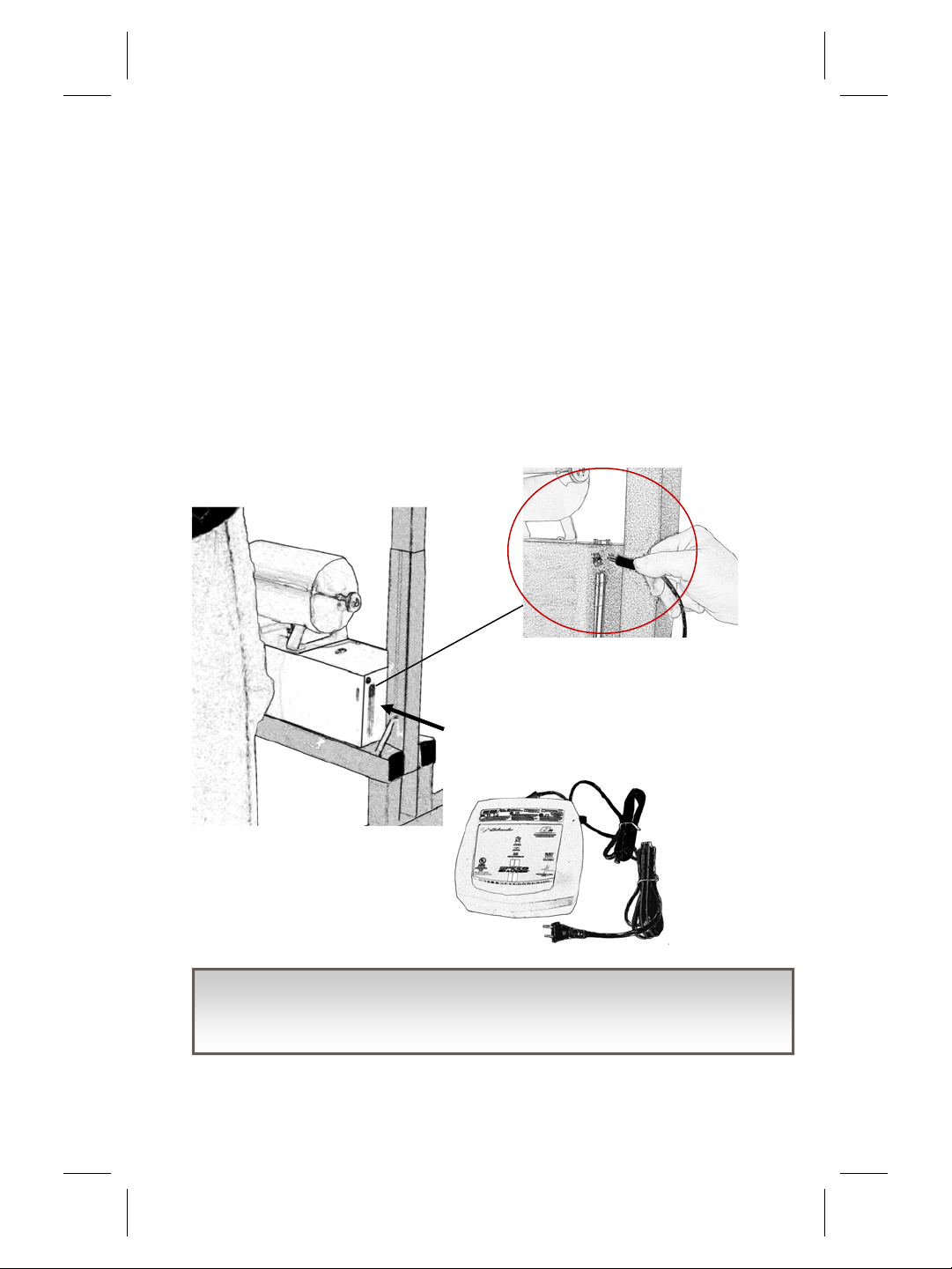
Contained Air System ......................................................9
Power On ........................................................................9
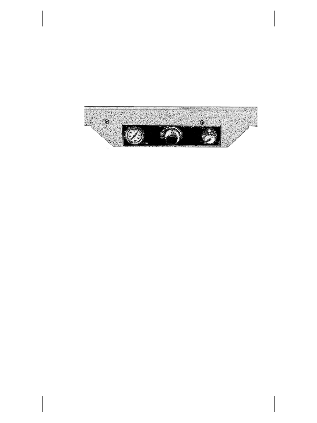
Control Panel.................................................................10
Handlebars ....................................................................12
Adjusting the Width....................................................... 13
Adjusting the Height......................................................14
PneuVest ....................................................................... 15
Using Lift Bar Options....................................................16
Hemiplegia Settings ...................................................... 17
Safety Straps .................................................................18
Locking Wheels .............................................................18
Attach Wheels ..............................................................19
Using the Unweighting System .....................................20
360 degree Unit .............................................................21
Troubleshooting ............................................................22
Specifications ................................................................25
Maintenance..................................................................26
Safety Requirements ..................................................... 27
Your Warranty ...............................................................28

4
Preface
This manual contains the operating instructions and service
requirements for the PneuWalker™ . The manual is designed for
clinical staffuse. The clinicians will instruct their patients and clients
in the proper use of the system and its accessories. Each operator
must read the operator manual in full before using the product for
the first time. Please read the manual carefully, noting the Safety
Requirements, before using the PneuWalker™ .
Liability Notice
Failure to follow the conditions set forth below shall absolve
Pneumex, Inc. from any responsibility for the safety, reliability, and
performance of this equipment.
Each independent user must be instructed in the proper use of the
system and its accessories.
The installation and assembly of the unit must comply with the
applicable local or state requirements. The equipment must be used
in accordance with the instructions for use. It is suggested that
operators of the PneuWalker™ receive approved training from
Pneumex, Inc. or their designee before operating the equipment.
Please call Pneumex at 800‐447‐5792 to find out more about our
training and certification programs.

5
Indications for use
Acute and chronic back pain
Assist in lifting patients out of bed or wheelchair
Balance
Bariatric patients
Cardiovascular
Knee, hip & ankle injury
Neurological patients
Orthopedic patients
Osteoporosis
Post surgical
Respiratory ailments
Ruptured disc — herniated / bulged
Contraindications
Spinal Fractures
Respiratory conditions which are exacerbated by pressure on the
rib cage
Tumors on the spine.
(This can sometimes be compensated for by taking more weight
through the legs or by using a thoracic vest).

6
Description
The PneuWalker™ unweighting system supports a person's body
weight during use. The pneumatic system lifts, or “unweights” the
user, reducing the amount of strain on a patient’s body. As the user
becomes stronger and can tolerate additional stress on the body,
the weight can be adjusted to make the body do more work. The
system can be used with most types of exercise equipment,
including, but not limited to: treadmills, steppers, bicycles, mini‐
trampolines, and balance boards. The PneuWalker™ can assist
with balance issues, getting patients in and out of wheelchairs or
beds, and increasing patient mobility.
The PneuWalker™ components include a frame with analog con‐
trols, two lift arms, a contained air system, a vest , and installation
hardware.

7
Control panel
Contained air system
Locking Wheels
Handlebar
Upright
Components
Cylinder
Handlebar
Air Box
Off‐On switch
Lift Arms
Cylinder Ports
Patient Ports
Drain and Air Valve

8
Unpacking
Your PneuWalker™ comes assembled.
Included with each PneuWalker™ is the operator/service manual,
charger and three PneuVest .
Before first Use
Before you use the PneuWalker™ for the first time, you must
charge the airbox. Screw the charger plug into the airbox and at‐
tach to a 110 outlet. When charging, the light will be orange. When
fully charged, the light will turn green.
Charger plug in
Charger
The Contained Air System must be charged before use. You must
plug in the charger each night. Failure may result in a dead battery.

9
Contained Air System
Charging the unit overnight will assure that there will be sufficient
battery power to operate the PneuWalker™ all day. When you
plug in the charger, it is recommended that you drain the air sys‐
tem. Put a container under the valve to catch water. The drain valve
is located underneath the airbox. There are two valves:
Valve A drains the main tank. This
should be done every night when
you charge the Contained Air
System. Pull down to drain .
Valve B is the air fitting that di‐
rects air to the cylinders.
Power on
Once the PneuWalker™ has been charged overnight , it is ready to
use. Adjust the unit to the width that will meet your needs (see
page2 13‐15)
Turn on the PneuWalker™ using the
toggle switch on top of the airbox.
The air tank must be drained weekly. Failure to do so may result in
damage to Airbox systems.
A
B

10
Control Panel
Before putting a patient in the PneuWalker™ you should famil‐
iarize yourself with the Control Panel located between the up‐
rights.
When to use Exercise or Balance Mode
Exercise Mode
Exercise mode lets the user perform vertical movements with con‐
sistent unweighting . For example: when you are retraining the sit
to stand motion, or working on stepping up and down steps.
Balance Mode
Balance mode lets the user perform exercises involving less ver‐
tical movement without fear of falling. The system supports the
entire body weight during loss of balance, allowing a fall of no
more than three to six inches.
OFF
OFF mode releases the air from the system quickly. This mode can
be used to re‐weight a person quickly if desired.
Pressure gauge Regulator knob Mode selector
Indicates the number of
pounds/kilograms the
system is Unweighting
Gradually increases (+) or
decreases (‐) the amount
of Unweighting lift)
Provides choices of
Exercise, Balance, or
Off(OFF‐EX‐BAL

11
Using the Unweighting System
Make sure unit has charged overnight before first use.
Turn power on at the air box.
3. Gently pull out he unweighting regulator knob and turn counter‐
clockwise until it comes to a stop.
4. Position the mode selector in the OFF position.
5. Fit the vest correctly to the subject and connect the vest securely to
the Patient Ports on the lift arms or the spreader bar if using the 360
degree attachment.
6. Turn the mode selector to Exercise. Only use the regulator knob
while in exercise mode.
7. Pull out the regulator knob and gradually turn it clockwise until the
gauge shows the desired lift. Take 40‐60% of body weight offan abil‐
ities patient, 20‐30% offa more able‐bodied patient. Use pain‐free or
pain‐tolerable as your guide.
8. Backing the control offslightly when you achieve the desired weight
will lock that weight in and keep the gauge from creeping up.
9. For activity, leave the mode selector in Exercise. For less vertical mo‐
tion, set the mode on Balance. Tighten safety straps if needed.
10. Monitor patient use.
11. To re‐weight, turn the mode selector to Exercise, then turn the regula‐
tor knob completely to the left. Do not force the knob (to re‐weight
quickly, turn the mode selector to Off).
12. When the pressure gauge reaches zero psi, turn the mode selector to
Off.

12
Handlebars
The handlebars are adjustable in height and can swing outward to
accommodate a person getting in and out of a wheelchair or bed.
Pull out Pin.
Swing handlebar to desired position.
If you need to maintain the handle‐
bars in the outward position, reinsert
Pin to hold.
To raise or lower handlebar, pull out
metal knob on the upright and slide
handlebar sleeve up or down as de‐
sired. Replace knob Pin to hold new
position. You will hear a click when
the knob and peg lock into
place at the new height.
Handlebar in outward position.

13
Adjust Width
The width of the PneuWalker™
can be easily adjusted . Wider
dimensions allow for use over tread‐
mills and narrower for easy
passage through interior
doorways.
There are 5 adjustment
possibilities. Each
hole is 2 “apart. Making
each adjustment 4” , 2” on
each side.
Position # 1: 26.5”
Position # 2 30.5”
Position # 3 34.5”
Position #4 38.5”
Position # 5 42.5”
On the front of the PneuWalker™ towards the bottom you will see
two gold Pin knobs. Pull both Pins out and turn 1/2 revolution to
unlock position prior to adjusting the width.
Once you have reached your desired width, twist the Pin knob to
hold the desired position. Make sure you use the same positions on
each side to maintain proper balance of the PneuWalker™.
Width Adjust Knob

14
Narrow to Wide
Pull both Pins out and lock wheels
on one side. Standing inside the
walker. Pull up on the handle bar
holding it close to the upright. Lift
upper part of unit and slide away
from locked side to desired width.
Fig 1
Relock the Pin knob to maintain
position. Unlock wheels. Repeat on opposite side.
Wide to Narrow
Pull both Pins out and lock wheels on one side. Standing inside the
walker. Pull up on the handle bar holding it close to the upright. Lift
upper part of unit and slide toward locked side to desired width.
Fig 1
Relock the Pin knob to maintain
position. Unlock wheels. Repeat
on opposite side.
Use the same positions on each
side to maintain proper balance
of the PneuWalker™.
Wheel base in extended position
Fig 1
Adjust the Height
New developments in the construction of our PneuWalker™ allow for
a greater range of heights to be accommodated. You therefore
should not have to adjust the height of your PneuWalker™.

15
PneuVest
A correctly fitted PneuVest is the key to success‐
ful unweighting. When choosing a vest, select
one that corresponds to the user’s waist size, not
to the chest size. The vests are color‐coded.
For complete vesting instructions see the
PneuVest instruction manual included with the
vest.
Attaching the Vest to the Lift Arm
Each shoulder strap on the vest has a D‐ring that attaches to the
lift arm utilizing a carabineer.
Most patients will be attached to patient port 1, moving to 2 or 3
only to increase the amount of weight lifted
You may attach the vest facing the control panel or facing away
from it depending upon the needs of the patient.
If you purchased the 360 degree attachment, attach the vest to
the spreader bar.
Use the control panel to unweight.
Wheelchair Users-See Vest Manual
After unweighting, ask the subject if the vest feels comfortable. Be
Before unweighting anyone, be sure the waist belt is snug and
that the carabineers are closed completely.

16
Using the Lift Arm
The lift arm options provide the ability to adjust weight capabilities
of the PneuWalker™
To maximize weight lifting capacity, attach the patient to Port 3 .
To maximize height capacity, attach the patient to Port 1. In Port
A, the cylinders remove equal weight on both sides. As the cylinder
is moved towards the upright to position B, less weight will be re‐
moved from that side of the patient, reducing total weight on that
side by 33%.
Hemiplegia Settings Grid
Cylinder
Port Setting
Keypad
Unweighting
Setting
Unweighted
Weight
Left Right Left‐
Side
Right‐
Side
A A 1 100
50 lbs. 50 lbs
B A 1 100 33.3 lbs 50 lbs
A B 1 100
50 lbs 33.3 lbs
Patient Port
Setting
1 2
B
A
Patient Port Maximum Vertical Maximum Weight

17
Hemiplegia Settings
The PneuWalker™ can be especially beneficial for patients with
one weak and one strong side as in Stroke patients. For example:
To lift 100% of the patient’s LEFT side, attach patient to right Port 1
and the right cylinder to Port A. Fig 1
To lift 67% of the patient’s LEFT side, attach patient to right Port 1
and the right cylinder to Port B. Fig 2
To adjust the cylinders, pull out the ring pin at the top, making sure
to secure the bar with your body. Move the cylinder to the desired
position and replace the pin.
1 2
B
A
Patient Port
Cylinder Port
Fig 1
A B
1
2
Fig 2
A B

18
Using Safety Straps
The PneuWalker™ comes with a safety feature that
will limit the amount of drop should a patient loose
their balance and fall. The nylon safety straps can be
adjusted to limit the distance (from 1 to 6 inches) a
patient can fall.
To set the distance make sure the strap is connected
to the cylinder via the carabineer. Open the cam
buckle and set the strap to the desired number in
inches. Securely close
the cam buckle.
Take care to make sure
that both straps are set
to the same distance.
Wheels
The PneuWalker™ has medical grade locking wheels to prevent
movement while assisting a patient with the Pneu‐Vest² or lifting
from a wheelchair or bed.
Simply step firmly on the
locking tab and the wheels
are locked in place. To un‐
lock lift locking tab.

19
Wheels
PneuWalkers™ are shipped without wheels attached.
To attach wheels:
1. Lay PneuWalker™ unit on it’s side
2. Locate wheels in packing. There is a
set marked front and a set marked back
3. Lock wheels
Wheels must be in locked position before
screwing into threaded holes on bottom of
unit. Push down on black tab until wheel
movement is locked.
4. Insert into hole, screw in a clockwise direction until wheel is flush
with bottom support bar.
5. Repeat with remaining wheels
6. Turn unit upright and unlock wheel by lifting up on black tab (by
hand or with
foot)
The Contained Air System must be charged before use. You must
plug in the charger each night. Failure may result in a dead battery.
Batteries as consumables are excluded from warranty.
Locked
Unlocked

20
Using the Unweighting System
To start using the PneuWalker™
1. Put vest on the PneuWalker™
and attach to the patient
2. Gradually remove desired
weight using the regulator
knob on the control panel
3. Choose Exercise or Balance
modes
4. Tension safety straps as
needed.
5. Monitor patient use.
6. Gradually release patient using
the regulator knob.
7. Remove vest.
The air tank must be drained regularly, daily or weekly depending
on humidity. Failure to do so may result in damage to Airbox
systems.
The Contained Air System must be charged before use. You must
plug in the charger each night. Failure may result in a dead battery.
Table of contents
Other Pneumex Mobility Aid manuals
Popular Mobility Aid manuals by other brands

Kid-Man
Kid-Man 04-7410 user manual

Lumex
Lumex RJ4200A Instructions & warranty information

Drive DeVilbiss Healthcare
Drive DeVilbiss Healthcare GIGO Instructions for use

Medline
Medline ELEMENTS MDS89664ELMB User instructions and warranty

Mackworth
Mackworth TA400 Service manual

Coopers
Coopers 8043C owner's manual