PNI PTZ720P User manual

Page 1
User manual
NVR PNI House PTZ720P

Page 2
Welcome
Thank you for purchasing our NVR!
This manual is designed to be a reference tool for the installation and operation of your system.
Here you can find information about this series NVR features and functions, as well as a detailed
menu tree.
Before installation and operation please read the following safeguards and warnings carefully!
Important Safeguards and Warnings
Do not place heavy objects on the NVR.
Do not let any solid or liquid fall into or infiltrate the NVR.
Please brush printed circuit boards, connectors, fans, machine box and so on regularly. Before
the dust cleaning please switch off the power supply and unplug it.
Do not disassemble or repair the NVR by yourself. Do not replace the components by yourself.
Environment
Please place and use the NVR between 0 and 40 degrees C. Avoid direct sunlight. Stay away
from heat source.
Do not install the NVR in damp environment.
Do not use the NVR in smoky or dusty environment.
Avoid collision or strong fall.
Please insure the NVR level installation in a stable workplace.
Please install in ventilated place. Keep the vent clean.
Use within the rating input and output scope.

Page 3
Directory
1 Production Introduction............................................................................................................................ 4
1.1 Product overview...........................................................................................................................4
1.2 Main functions ...............................................................................................................................4
2 Open-package check and cable connections.......................................................................................... 6
2.1 Open-package check..................................................................................................................... 6
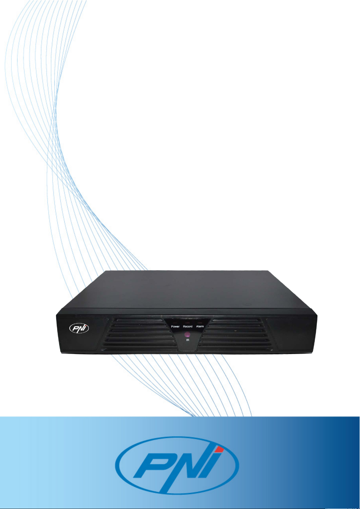
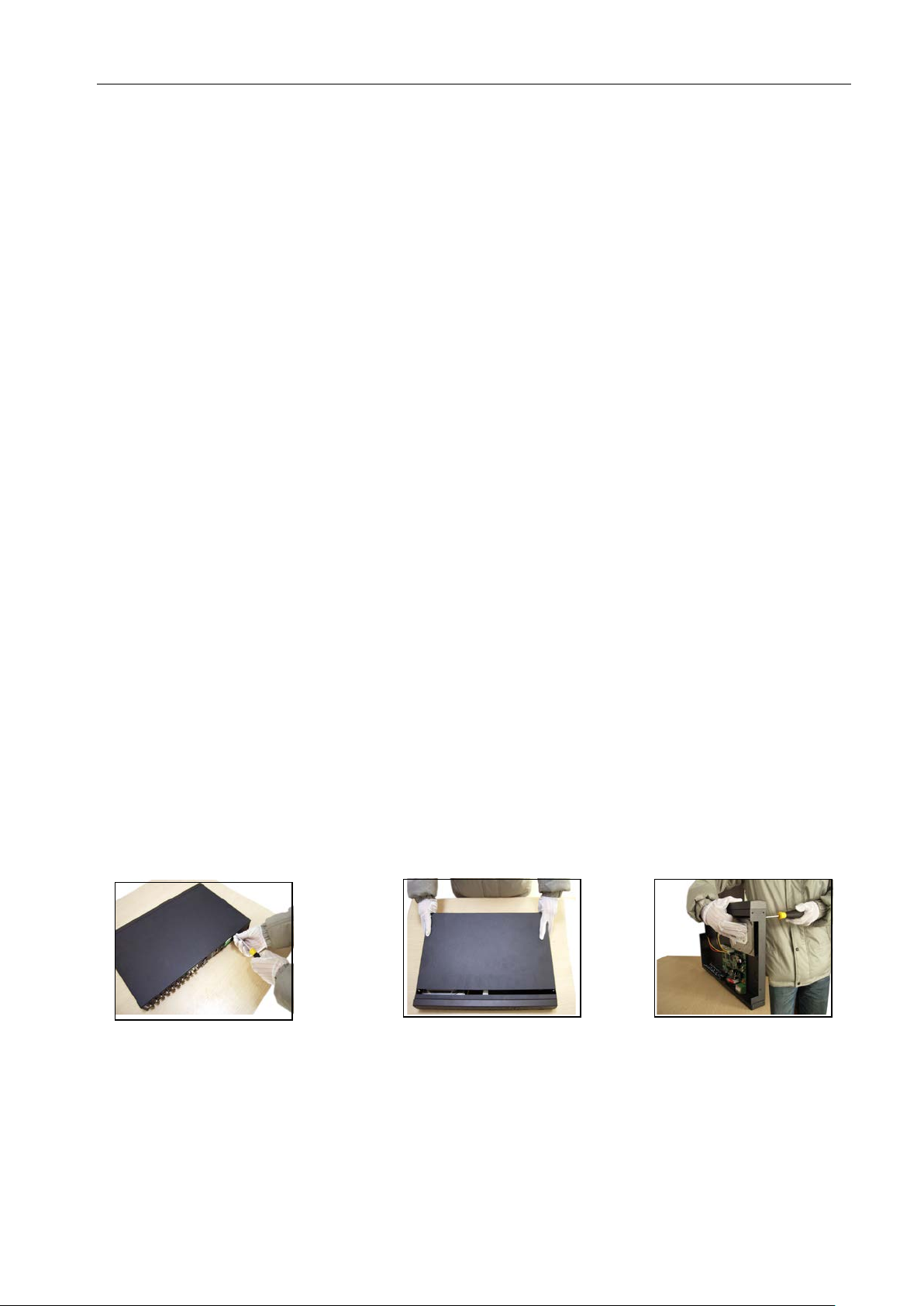
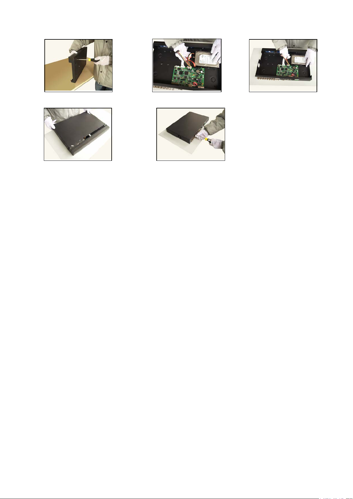
2.2 Hard disk installation .....................................................................................................................6
2.3 Audio and video input and output connections ............................................................................. 7
2.3.1 Video input connections......................................................................................................7
2.3.2 Video output connections and options................................................................................ 8
2.3.3 Audio signal input................................................................................................................8
2.3.4 Audio signal output.............................................................................................................. 8
2.4
、
PTZ decoder connections 9
2.5 Front equipment grounding note 9
2.6 Speed dome connections..............................................................................................................9
2.7 Turn on.........................................................................................................................................10
2.8 Turn off......................................................................................................................................... 10
2.9 System Login...............................................................................................................................10
3.0 Preview.........................................................................................................................................11
3.1 Desktop shortcut menu ................................................................................................................11
3.1.1 Main menu.........................................................................................................................25
3.1.2 Playback............................................................................................................................12
3.1.3 Record Mode.....................................................................................................................20
3.1.5 PTZ control........................................................................................................................ 21
3.1.6 Color setting......................................................................................................................22
3.1.7 Output adjust.....................................................................................................................22
3.1.8 Logout ...............................................................................................................................22
3.1.9 Window switch...................................................................................................................23
3.1Main menu...........................................................................................................................................24
3.2.1 Main menu navigation.............................................................................................................. 24
3.3Record.......................................................................................................................................... 31
3.3.1 Record Config ...................................................................................................................31
3.3.2 Snapshot Storage.............................................................................................................32
3.3.3 Playback............................................................................................................................33
3.3.4 Backup ..............................................................................................................................33
3.4 Alarm............................................................................................................................................29
3.4.1 Motion Detect.................................................................................................................... 29
3.4.2 Video Blind........................................................................................................................32
3.4.3 Video Loss......................................................................................................................... 33
3.4.4 Alarm input ..........................................................................Error! Bookmark not defined.
3.4.5 Alarm output........................................................................Error! Bookmark not defined.
3.4.6 Abnormal ...........................................................................................................................33
3.5 System.........................................................................................................................................34
3.5.1 General.............................................................................................................................. 35

Page 4
3.5.2 Encode.............................................................................................................................. 36
3.5.3 Network............................................................................................................................. 37
3.5.4 NetSevice.......................................................................................................................... 38
3.5.5 GUI Display.......................................................................................................................44
3.5.6 PTZ.................................................................................................................................... 46
3.5.7 RS232 ...............................................................................................................................46
3.5.8 Tour.................................................................................................................................... 47
3.6 Advanced.....................................................................................................................................48
3.6.1 HDD Manage..................................................................................................................... 48
3.6.2 Account.............................................................................................................................. 49
3.6.3 Online user........................................................................................................................52
3.6.4 Output adjust.....................................................................................................................52
3.6.5 Auto maintain.....................................................................................................................53
3.6.6 Restore.............................................................................................................................. 51
3.6.7 Upgrade............................................................................................................................. 54
3.6.8 Device Info........................................................................................................................54
3.7 Info............................................................................................................................................... 52
3.7.1 HDD info............................................................................................................................ 52
3.7.2 BPS ...................................................................................................................................54
3.7.3 Log.....................................................................................................................................55
3.7.4 Version ..............................................................................................................................56
3.8 Shut down system.......................................................................................................................57

Page 5
1 Production Introduction
1.1 Product overview
The series DVR is designed specially for security and defence field which is an outstanding digital
surveillance product. It introduces embedded LINUX operating system which is more stable. It introduces
standard H.264mp video compressed format and G.711A audio compressed format which insures the
high quality image, low error coding ratio and single frame playing. It introduces TCP/IP network
technology which achieves the strong network communication ability and telecommunication ability.
The series DVR can be used individually or online applied as a part of a safety surveillance network.
With the professional network video surveillance software it achieves the strong network communication
ability and telecommunication ability.
The series DVR can be applied in the bank, telecom, electric power system, judicial system,
transportation, intelligent housing, factory, storehouse, water conservancy and so on.
1.2 Main functions
Real-time surveillance
analog interface and VGAinterface (VGAinterface is equipped selectively)
surveillance function through monitor or display
Storage
non-working hard disk dormancy processing which is convenient to radiate heat, reduce power and
extend the life-span
special storage format which insures the data safety
Compression
real-time compression by individual hard disk which insures the audio and video signal stable
synchronization
Backup
through SATA interface and USB interface such as USB equipment, removable hard disk and so on
through net download the files in the hard disk
Playback

Page 6
individual real-time video recording as well as searching, playback, network surveillance, recording
check, downloading and so on
multi-playback mode
zoom at arbitrary region
Net operating
through net tele-surveillance in the real time
tele-PTZ control
tele-recording check and real-time playback
Communication interface
RS485 interface which fulfills the alarm input and PTZ control
standard ethernet network interface which fulfills the telecommuting function
Intelligent operating
mouse action function
fast copy and paste operating for the same setting

Page 7
2 Open-package check and cable connections
2.1 Open-package check
When you receive the DVR, please check first .
First, please check whether there is any visible damage to the package appearance. The protective
materials used for the package of the DVR can protect most accidental clashes during transportation.
Then, please open the box and get rid off the plastic protective materials. Check whether there is
any visible damage to the DVR appearance.
At last, please open the machine crust and check the data wire in the front panel, power wire, the
connection between the fan power and the main board.
Front panel and rear panel
♦The key function specification in the front panel and the interface specification in the real panel
are in the specification.
♦Please check the product type in the front panel whether is accordant with the product type you
order.
The label in the real panel is very important for the after service. Please protect it carefully. When
you contact us for after service, please provide the product type and serial number in the label.
2.2 Hard disk installation
For the first use,please install the hard disk.
①disassemble the screw ②disassemble thecover ③fix the screw of hard disk

Page 8
④fix the screw of hard disk ⑤connect the data wire ⑥connect the power wire
⑦cover the machine ⑧fix the cover
2.3 Audio and video input and output connections
2.3.1 Video input connections
The video input port is BNC connector plug. The demand of input signal is PAL/NTSC
BNC(1.0VP-P,75Ω).
2.3.2 Video output connections and options
The video output is divided into PAL/NTSC BNC(1.0VP-P,75Ω) and VGA output(selective
configuration).
Audio port is BNC connection.
2.3.4 Audio signal output
2.4
、
PTZ decoder connections
A. The grounding of the PTZ decoder and DVR must be shared otherwise the common-mode
voltage will lead to the PTZ control failure. The shielded twisted pair is recommended.
B. Avoid the entrance of high voltage. Make the layout reasonably. Take precaution from the
thunder.
C. In the outlying end connect 120Ω resistance paralleled to reduce the inflection and insure the

Page 9
signal quality.
D. The 485AB lines of DVR can not connected with other 485 output equipments paralleled.
E. The voltage between the AB lines of the decoder must be less than 5V.
2.5
、
Front equipment grounding note
Bad grounding can lead to the burnout of the chip.
2.6 Speed dome connections
1、Connect the 485 lines of the speed dome with the DVR 485 interface.
2、Connect the video line with the DVR video input.
3、Electrify the speed dome.

Page 10
3 Basic operation
Note: The button in gray display indicates nonsupport.
2.7 Turn on
Plug the power supply and turn on the power supply switch. Power supply indicator light shining
indicates turning on the video recorder. After the startup you will hear a beep. The default setting of video
output is multiple-window output mode. If the startup time is within the video setting time, the timing video
recording function will start up automatically. Then the video indicator light of corresponding channel is
shining and the DVR is working normally.
Note:1. Make sure that the input voltage corresponds with the switch of the DVR power supply.
2. Power supply demands: 220V±10% /50Hz.
Suggest using the UPS to protect the power supply under allowable conditions.
2.8 Turn off
There are two methods to turn off the DVR. Entering [main menu] and choosing [turn off] in the [turn
off the system] option is called soft switch. Pressing the power supply switch is called hard switch.
Illumination:
1、Auto resume after power failure
If the DVR is shut down abnormally, it can automatically backup video and resume previous
working status after power failure.
2、Replace the hard disk
Before replacing the hard disk, the power supply switch in the real panel must be turned off.
2.9 System Login
When the DVR boots up, the user must login and the system provides the corresponding functions
with the user purview. There are three user settings. The names are admin, guest and default and
these names have no password. Admin is the super user purview; guest and default’s permissions are
preview and video playback. User admin and guest’s password can be revised, while their permissions

Page 11
can’t be revised; user default is the default login user whose permission can be revised but not its
password.
Picture 3.1 System Login
Password protection: If the password is continuous wrong three times, the alarm will start. If
the password is continuous wrong five times, the account will be locked. (Through reboot or after
half an hour, the account will be unlocked automatically).
For your system security, please modify your password after first login.
3.0 Preview
You can right click mouse to choose the switch between the windows.
The system date, time and channel name are shown in each viewing window. The surveillance video
and the alarm status are shown in each window.
1 Recording status 3 Video loss
2 Motion detect 4 Camera lock
Table 3.1 Preview icon
3.1 Desktop shortcut menu
In preview mode you can right click mouse to get a desktop shortcut menu. The menu includes:
main menu,record mode,playback,PTZ control,High Speed PTZ,Alarm Output,color
Setting,Output adjust,Logout,view1/4/8/9/16 screens.

Page 12
Picture 3.2 Shortcut Menu
3.1.1 Main menu
When you login, the system main menu is shown as below.
Picture3.3 Main Menu
3.1.2 Playback
There are two methods for you to play the video files in the hard disk.
1、In the desktop shortcut menu.

Page 13
2、Main menu>Record->Playback
Note: The hard disk that saves the video files must be set as read-write or read-only state.(4.5.1)
Picture 3.4 video playback
1. listed files 2. file information 3. file searching
4. file backup 5. Operation hint 6. Playback control
Note: The storage must be installed before the file backup. If the backup is terminated, the
already backup can playback individually.

Page 14
Picture 3.5 detect the storage
Detect: Detect the storage connected with the DVR such as hard disk or universal disk.
Erasure: Choose the file to delete and click erasure to delete the file.
Stop: Stop the backup.
Backup: Click backup button and the dialog box is popped up. You can choose the backup file
according to the type, channel and time.
Picture 3.6 recording backup
Remove
:
Clear the file information.
Add
:
Show the file information satisfying the set file attributes.
Start/Pause
:
Click the play button to start the backup and click the pause button to stop the
backup.
Cancel:During backup you can exit the page layout to carry out other functions.

Page 15
【File searching】Search the file according to the searching parameter.
Picture 3.7 file searching
File type: Set the searching file type.
Channel: Set the searching channel.
Start Time: Set the searching time scan.
【Playback control】Refer to the following sheet for more information.
Button Function Button Function
/
Play/pause
Backward
Stop
Slow play
Fast play
Previous frame
Next frame
Previous file
Next file
Circulation
Full screen
Table 3.2 Playback control key
Note: Frame by frame playback is only performed in the pause playback state.
Special functions
:
Accurate playback
:
Input time (h/m/s) in the time column and then click playbutton. The
system can operate accurate playback according to the searching time.
Local zoom
:
When the system is in single-window full-screen playback mode, you can drag your
mouse in the screen to select a section and then left click mouse to realize local zoom. You can right click
mouse to exit.

Page 16
3.1.3 Record Mode
Please check current channel status: “○” means it is not in recording status, “●” means it is in
recording status.
Picture 3.8 Record Mode
【Schedule】Record according to the configuration.
【Manual】Click the all button and the according channel is recording no matter the channel in any
state.
【Stop】Click the stop button and the according channel stops recording no matter the channel in
any state.
3.1.4 PTZ control
Operation interface is as followed. The functions include: PTZ direction control, step, zoom, focus,
iris, setup operation, patrol between spots, trail patrol, boundary scan, assistant switch, light switch,
level rotation and so on.
Note1. DecoderA(B)line connects with DVRA(B)line. The connection is right.
2. Click [main menu] >[system configuration] >[PTZ setup] to set the PTZ parameters.
3. The PTZ functions are decided by the PTZ protocols.
Picture 3.10 PTZ setup

Page 17
【Speed】Set the PTZ rotation range. Default range: 1 ~ 8.
【Zoom】Click / button to adjust the zoom multiple of the camera.
【Focus】Click / button to adjust the focus of the camera .
【Iris】Click / button to adjust the iris of the camera.
【Direction control】Control the PTZ rotation. 8 directions control is supportive.(4 directions in Front
panel is supportive )
【High speed PTZ】Full-screen show channel image. Left press mouse and control PTZ to rotate
orientation. Left press mouse and then rotate the mouse to adjust the zoom multiple of the camera.
【Set】Enter the function operation menu.
【Page switch】Switch between different pages.
Special functions
:
1
、
Preset
Set a location for the preset, calls the preset points, PTZ automatically turns to the setting
position
1)Preset option
Set a location for the preset, procedure is as follows:
Step1: in Picture 3.10, click the Direction button will turn into preset position , click the Settings
button to enter Picture 3.11.
Step 2: click the Preset button , then write the preset points in the input blank,
Step 3: click Settings button, return the Picture 3.10 Complete setup, that is the preset points and
preset position corresponds.
Clear Preset:Input preset points, click Remove button, remove the preset。

Page 18
Picture 3.11 Preset Settings
2)Preset Point Calls
In Picture 3.10, click Page Shift button, enter PTZ control interface as shown in Picture 3.12. In
the input blank, write the preset points, then click Preset button, PTZ turn to the corresponding
preset point.
Picture 3.12 PTZ Control
2
、
Cruise between Points
Multiple preset points connected cruise lines, call cruise between points, the PTZ run around on
the line
1)Cruise Between Points Settings
Cruise lines is connected by multiple preset points, setting procedure is as follows:
Step1: In Picture 3.10, the Direction key will turn PTZ to designated location , click Settings
button to enter Picture 3.13,
Step 2: click Cruise buttons, the write proper value into the Cruise Line and Preset Points blank,
then click Add Preset Points button, complete setting (also can add and delete cruise line which has
Preset button Preset point input blank
Value input blank

Page 19
been set up)
Step 3: repeat step1 and step2 , until set out all the preset designated cruise lines。
Remove Preset:Please input preset value in the blank, click Remove Preset button, then
remove the preset points.
Remove Cruise Line:Input the number of cruise line, click Remove Cruise Lines button, then
remove the cruise lines set。
Picture 3.13 Cruise Between Points Settings
2)The Calls of Cruise between Points
In Picture 3.10, click Page Shift button, enter PTZ control menu as shown in Picture 3.12. Please
input the number of cruise in the value blank, then click Cruise between Points button, PTZ begins to
work on the cruise line. Click Stop button to stop cruise.
3
、
Scan
PTZ also can work on the preset scan line repeatedly.
1)Scan setup
Step1:In Picture 3.10, click Setup button ,enter Picture 3.14;
Step2:Click Scan button,the input proper value in the scan value blank;
Step3:Click Start button, enter Picture3.10,here you can set the following items: Zoom、
Focus、Aperture、Direction and so on. Click Setup button to go back Picture 3.14;
Step4:Click End button to complete setup。Click the right button of the mouse to exit.
Cruise Button
Cruise Line Blank
Preset Points Blank

Page 20
Picture 3.14 Scan Setup
2)Scan Calls
In Picture 3.10, click Page Shift button, then enter PTZ control menu as shown in Picture 3.12.
Please input the number of scan in the value blank , then click Scan button,PTZ begins to work on
the scan line . Click Stop button to stop.
4
、
Boundary Scan
1)Boundary Scan setup
Step1:In Picture 3.10, click Direction button to turn the PTZ to preset direction, then click Setup
button enter Picture 3.15, select the left boundary, return to Picture 3.10;
Step2:Please click direction arrows to adjust PTZ direction, click Setup button enter Picture3.15,
then select the right boundary ,return to Picture 3.10;
Step3: Complete setup, that is the position of left and right boundary
Picture 3.15 Boundary Scan Setup
Scan value blank
Scan Button
Line scan button
border
Table of contents
Other PNI DVR manuals