PNI DK110 User manual

PNI DK110
Access control keypad / Клавиатура за контрол на достъпа
/ Zugangskontrolltastatur / Teclado de control de acceso /
Clavier de contrôle d’accès / Beléptető billentyűzet / Tastiera
controllo accessi / Toegangscontrole toetsenbord / Klawiatura
kontroli dostępu / Tastatura control acces

EN User manual ....................... 3
BG Ръководство за употреба .......... 17
DE Benutzerhandbuch ................. 33
ES Manual de usuario .................. 47
FR Manuel utilisateur .................. 61
HU Használati utasítás ................. 76
IT Manuale utente ................... 90
NL Handleiding ...................... 105
PL Instrukcja obsługi .................. 120
RO Manual de utilizare ................ 135

3 - User manual
Description
PNI DK110 is a stand-alone access control device and a card
reader compatible with EM cards.
Main features
• Low power consumption, less than 30 mA in standby.
• Wiegand interface. WG26 and WG34 input and output.
• Card reading time: less than 0.1 seconds.
• Backlit keyboard.
• Supports external door bell connection.
• Access modes: RFID card, PIN code, card and PIN code.
Technical specifications
Supply voltage 12V
Card reading distance 2 - 5 cm
Compatible cards EM 125KHz
Electric lock output load ≤3A
Standby current 30mA
User capacity maximum 2000
Door relay time 0 - 99 seconds (adjustable)
Working temperature -26°C ~ +80°C
4 - User manual
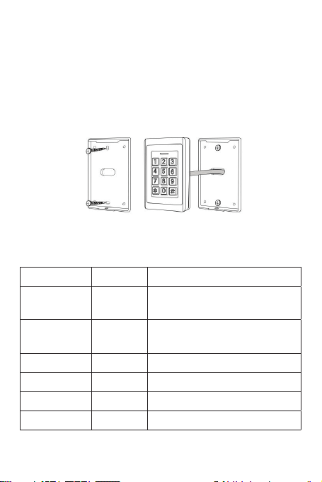
Installation
Choose the installation location and make holes in the wall
that match the holes in the mounting bracket. Secure the wall
bracket with the screws included in the package. Pass the cables
through the hole in the middle of the bracket. Connect the
cables. Insulate unused cables to avoid short circuit.
Wiring
Color ID Description
Green D0 Wiegand input (Wiegand
output in card reader mode)
White D1 Wiegand input (Wiegand
output in card reader mode)
Yellow OPEN Access button input
Red +12V + 12V DC power input
Black GND - 12V DC power input
Blue NO NO connector (normally open)

5 - User manual
Violet COM Common connector
Orange NC NC connector (normally
closed)
Pink BELL_A Door bell terminal
Pink BELL_B Door bell terminal
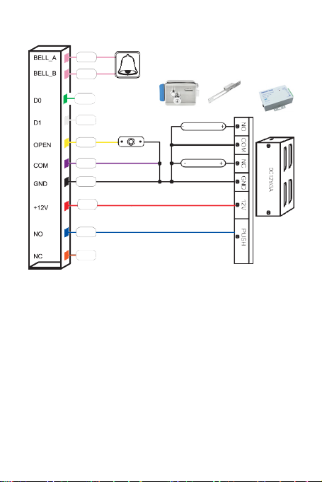
Connection diagram
1. Common power supply
Pink
Pink
Door bell
Power supply
(eg. PNI ST3.4A)
Green
White
Yellow
Purple
Black
Access button
Fail Safe Electromagnet
Fail Secure electric lock
BELL_A
BELL_B
Blue
Silvercloud YE910 Silvercloud YS810
Orange
Red
6 - User manual
2. Special power supply
Pink
Pink
White
Yellow
Purple
Black
Red
Blue
Orange
Door bell
Access button
NO Fail Secure electric lock
NC Fail Safe electromagnet
Power supply
(ex. K80)
Silvercloud YE910 Silvercloud YS810
Green
7 - User manual
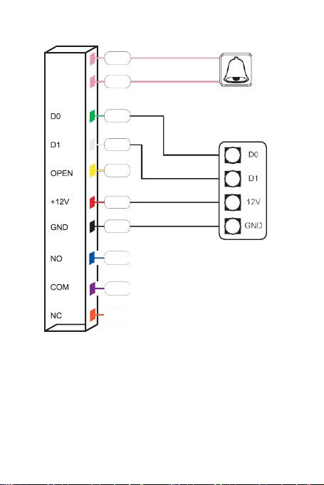
3. Card reader mode
Pink
BELL_A
BELL_B Pink
Green
Door bell
White
Yellow
Red
Black
Wiegand card reader
Orange
Blue
Purple

8 - User manual
Audible and luminous warnings
Status LED Sound
Standby Red
Keyboard Beep
Successful operation Green Beep ...
Operation error Beep-Beep-Beep
Enter programming mode Red
blinks Beep
Exit programming mode Red Beep
Open the door Green Beep ...
Advanced settings
To enter programming mode, briefly press the * key. The red
LED starts flashing.
To exit programming mode, briefly press the * key. The red LED
stays on.
1. Add user
Change Master code
* Master code # 0
New code # New code #
Note: The Master code must contain 6 digits. The default

9 - User manual
Master code is 999999.
Add card by reading the card
* Master code # 1
Read the first card # Read the second card # Read the third card
# ..
Note: Cards can be added one after the other.
Add card by card number
* Master code # 1
Input card number (8 or 10 digits) #
Note: Cards can be added one after the other.
Add ID + card
* Master code # 1
Input ID number # Read the card #
Note: The ID number can be from 1 up to 2000. The users
added with ID number can be easily found and deleted.
Add PIN code
* Master code # 1
Input ID number # Input the 4-digit PIN code #
Note: The ID number can be from 1 up to 2000.

10 - User manual
2. Delete user
Delete card
* Master code # 2
Read the card or Input the card number (8 or 10 digits) #
Note: Cards can be deleted one after the other.
Delete ID number
* Master code # 2
Input the ID number #
Note: If an user loses its card, you can delete the user by ID
number.
Delete all users
* Master code # 2
0000 #
Note: This key combination will delete all PINs and all cards
except the public PIN.
3. Access modes
By card
* Master code # 30 #
Note: Only the card opens the door, the keypad in not active.
This manual suits for next models
1
Table of contents
Languages:
Other PNI Keypad manuals


