PNI DK220 User manual

PNI DK220
Access control keypad/Клавиатура за контрол на достъпа/
Zugangskontrolltastatur/Teclado de control de acceso
Clavier de contrôle d’accès/Beléptető billentyűzet
Tastiera controllo accessi/Toegangscontrole toetsenbord
Klawiatura kontroli dostępu/Tastatura control acces

EN User manual ............................. 3
BG Ръководство за употреба ............... 25
DE Benutzerhandbuch ....................... 50
ES Manual de usuario ........................ 74
FR Manuel utilisateur ........................ 98
HU Használati utasítás ....................... 122
IT Manuale utente ......................... 146
NL Handleiding ............................ 170
PL Instrukcja obsługi ........................ 194
RO Manual de utilizare ....................... 218

3 - User manual
Description
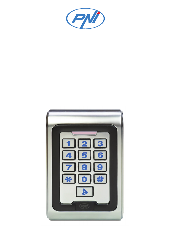
PNI DK220 is a stand-alone access control device and proximity
reader. It is equipped with two relays for two-door control and
supports a maximum of 2000 users, each user can have a PIN code
and an access card.
The keypad can be connected to an electromagnetic key, an alarm
system, a doorbell, an access button or a door sensor.
The device has 7 operating modes: Wiegand card reader, access
control for one door, access control for two doors, access control
with external card reader for two doors, two interconnected units for
two doors, anti-passback for one door and two-door anti-passback.
Main features
• Aluminum alloy housing with IP65 water resistance class
• Built-in 125KHz card reader
• Illuminated numeric keys. The key light can be programmed as
follows: Normal ON, Normal OFF or Human-Approach ON
(lights up when it detects motion).
• Tamper alarm, door sensor trigger alarm, duress code alarm This
code can be used when the user is forced to threaten to open the
door. When typing this code, the door will open but will activate a
silent alarm ).
• Add and delete cards with the administrator card.
• Register and delete users by keys.

4 - User manual
Technical specifications
Supply voltage 12V AC/DC
Standby consumption <25mA
Electric lock output load <1A
Alarm output load <1A
Doorbell output load <1A
Card reading distance maximum 40 mm
User capacity maximum 2000
Compatible cards EM 125Khz/HID 125KHz
Card transmission format 26-37 bit Wiegand
Keypad transmission format 4 bit and 8 bit and virtual card
number
Working temperature -26°C ~ +80°C
Installation
Choose the installation location and make holes in the wall that
match the holes in the mounting bracket. Secure the wall bracket
with the screws included in the package. Pass the cables through the
slot in the middle of the holder. Connect the cables. Insulate unused
cables to avoid short circuit.

5 - User manual
Wiring
Zone 1
BELL_A Pink Doorbell button
BELL_B Pink Doorbell button
ALARM+ Red Alarm connector
AC2 Black AC input
OPEN2 Yellow Access button
D_IN2 Brown Door contact
ALARM2- Gray Alarm 2
NO2 Blue Relay 2 NO
COM2 Purple Relay 2 COM
NC2 Orange Relay 2 NC

6 - User manual
Zone 2
D0 Green Wiegand ouput D0
D1 White Wiegand ouput D1
AC1 Red AC1 (+ 12V)
GND Black GND
OPEN1(LED) Yellow Access button (for green LED)
D_IN1(BZ) Brown Door contact (for buzzer)
ALARM1- Gray Alarm 1
NO1 Blue Relay 1 NO
COM1 Purple Relay 1 Com
NC1 Orange Relay 1 NC

7 - User manual
Audible and luminous warnings
Status LED Buzzer
Standby Red blinks
Press key Di
Read card Green Di.
Door 1 open Green Di.
Door 2 open Green blinks Di.
Successful operation Green Di.
Operation failed DiDiDi
PIN input Red
Read card & PIN Red
Multiple card reading Red
Under menu Red
Under settings Orange
Administrator card enter Orange DiDi
Administrator card exit Red blinks Di.
Alarm Red blinks
quickly Alarm

8 - User manual
Quick Programming Guide
1. Administrator settings
* Master code #
00
Input the new
Master code #
Repeat the new
Master code #
Change Master code.
Note: The default
master code is 999999.
The master code must
have between 6 and 8
digits.
01 Read the card
Master card
registration for
adding cards.
Note: Default: zone 1.
02 Read the card
Master card
registration for
deleting cards.
Note: Default: zone 1
03 Read the card “Duress” alarm card
registration for zone 1
04 Read the card “Duress” alarm card
registration for zone 2

9 - User manual
* Master code #
05 Input the 8-digit
PIN
Input the “duress”
PIN code for zone1
Note: The first digit
of the PIN must be
1 for zone 1.
06 Input the 8-digit
PIN
Input the “duress”
PIN code for zone2
Note: The first digit
of the PIN must be
2 for zone 2.
07 0000 # Delete all users
51 Master open Lock 1
52 Master open Lock 2
Note:
The “duress” PIN and the “duress” card can be used when the user is
forced to open the door. When typing this code or reading this card,
the door will open but at the same time it will send an alarm signal.

10 - User manual
2. User settings for Zone 1 and Zone 2
Add user card
* Master code #
11
(for Zone 1)
21
(for Zone 2)
Read the card
Input ID # Read the card
Input card number #
Input ID # Input card number #
Note: Users can be added one after the other without leaving
programming mode. User ID can contain between 1 and 4 digits, in
the range 1 - 2000. 1, 01, 001 and 0001 all means 1.
Add user PIN
* Master code #
11
(for Zone 1)
21
(for Zone 2)
Input ID # Input PIN #
Note: The PIN can have 4 to 6 digits. The first digit must be 1 for
Zone 1 and 2 for Zone 2. “1234” is reserved, cannot be set as PIN.

11 - User manual
Delete user
* Master code #
12
(for Zone 1)
22
(for Zone 2)
Read the card
Input ID #
Input card number #
Note: Users can be deleted one after the other without leaving the
programming mode.
Delete all users
* Master code # 07 0000 #
Note: This command deletes all users in Zone 1 and Zone 2.
Access modes
* Master code #
13
(for Zone 1)
23
(for Zone 2)
0 # By card
1 # By card + PIN
2 # By card or PIN
(default setting)
Open door delay
* Master code #
14
(for Zone 1)
24
(for Zone 2)
0 - 99 # Default setting 5

12 - User manual
Set door closing modes
* Master code #
15
(for Zone 1)
25
(for Zone 2)
0 #
Pulse mode (default
setting). Each time a
code is entered or a
valid card has been read,
the door will open and
close automatically after
the set time interval
(between 0.05 sec. and
99 sec).
1 #
Toggle mode. Each time
a code is entered or a
valid card has been read,
the door will open but will
not close until the code is
entered again or the card
will be read.
Open the door with several cards
* Master code #
16
(for Zone 1)
26
(for Zone 2)
1 - 10 # Default setting 1
Note: The door will only open after all the cards have been read. For
example, by order * Master code # 16 3 #, you have to read 3 cards in
a row to open the door. This setting is only useful if you have set the
keypad to card access mode.

13 - User manual
Add user cards in series
* Master code #
17
(for Zone 1)
27
(for Zone 2)
Input ID #, Input card number
#, Input quantity #
Note: Card numbers must be consecutive (between 8 and 10
characters). Card quantity is between 1 and 2000.
3. System settings
* Master code #
30 0-15 # Setting the unit code (Facility
Code). Default: 0
31
0 # Reader Wiegand
1 # One-door stand-alone access
control (default setting)
2 # Stand-alone access control for
two doors
3 # With external reader for two
doors
4 #
Two interconnected units for
two doors
(protection when opening
multiple doors)

14 - User manual
* Master code #
31
5 # Anti-passback for a door
6 # Anti-passback for two doors
32 26-37 # Wiegand format setting 26 34
37. Default 26.
33 0-2 #
Keypad transmission format
setting: 0 1 2
After resetting, this setting
keeps unchanged.
* Master code #
34 1-3 #
Set alarm duration
(default setting 1 minute)
After resetting, this setting
keeps unchanged.
35
0 # Safe mode 1. Normal mode.
(default setting)
1 #
Safe mode 2.
If the wrong code is entered or
an invalid card is read 10 times
in a row within 10 minutes, as a
safety precaution, the system
shuts down.

15 - User manual
* Master code # 35 2 #
Safety mode 3. Alarm mode.
If the wrong code is entered or
an invalid card is read 10 times
in a row within 10 minutes,
as a precaution, the external
alarm (if connected) and the
buzzer built into the keypad
will be triggered.
4. Optional user settings
* Master code #
41
0 #
Buzzer o.
The buzzer remains active
only when the device enters
programming mode.
1 # Active key sound
(default setting)
42
0 # Key backlight o
1 # Key backlight on
2 #
Automatic mode. Normally, the
key light is o but turns on when
human presence is detected.

16 - User manual
* Master code #
43 0 # LED o when the device is in
standby.
1 # The LED flashes when the device is
in standby mode. (default setting)
Important notes
1. The master code must have 6-8 digits.
2. The code “duress” must have 8 digits. The first digit of the code
must be 1 for Zone 1 and 2 for Zone 2.
3. User PIN must have 4-6 digits. The first digit of the PIN must be
1 for Zone 1 and 2 for Zone 2.
4. User ID can be any number between 1 and 2000.
5. The card number must have between 8 and 10 digits. If the card
number contains less than 8 digits, add 0 in front of the code.
6. Open door delay time: between 0 and 99 seconds. 0 = 50mS
7. When a user card is registered in the device, the device will
automatically generate a PIN 1234 that cannot unlock the door.
8. If an invalid master PIN is entered, the device enters standby after
5 seconds. If a valid master PIN is entered, the device enters standby
mode after 30 seconds.
9. When using the keypad, pressing the # key confirms the previously
executed key command. When adding or deleting cards one after the
other, pressing the # key indicates the end of the cycle, and pressing
the * key indicates exit from this operation.
10. When you add cards in series, the device automatically assigns
an ID number and a card number. The ID number and card number
increase automatically with each card added, up to a maximum of
2000.

17 - User manual
11. The operating mode and transmission format of the keypad are set
at the factory. The user can change these settings as needed. After
resetting the device, this setting remains unchanged.
12. After successfully registering users in Zone 1, the LED turns
green. After successfully registering users in Zone 2, the green LED
flashes.
5. Master card operations
Add user for Zone 1
Read the master add card, then Read the user cards one after the other,
and finally Read the master add card again.
Delete user for Zone 1
Read the master delete card, then Read the user cards one after the
other, and finally Read the master delete card again.
6. User operations
By card
Read the card. The lock will unlock.
If you have set multiple cards for the door opening (between 2 and
10), read all the cards one after another within 5 seconds, after which
the lock will unlock.
By card + PIN
Read the card, input the PIN (4 or 6 digits) +#. The lock will unlock.

18 - User manual
By card or PIN
Read the card. The lock will unlock. Or input the PIN +#. The lock
will unlock.
Change PIN without entering programming mode
* read user card, input old PIN #, input new PIN # repeat new PIN
or
* input ID number # input old PIN #, input new PIN # repeat new PIN
Note: The PIN for Zone 1 must start with 1, and the PIN for Zone 2
must start with 2.
7. Alarm function
Tamper alarm
If the device is disassembled by burglary, the internal buzzer and
external alarm (if connected) will sound.
Open door alarm
If you have connected a wired door sensor to the access control
keypad and this sensor will trigger, the internal buzzer and external
alarm (if connected) will sound.
To turn o the alarm:
Read the user card or master card, or input the master PIN.
If you do not perform any operation, the alarm will turn o
automatically after 1 minute.

19 - User manual
“Duress“ alarm
If the “duress” card is read or the “duress” PIN code is entered
on Zone 1 or Zone 2, the lock will open and, at the same time, the
external alarm will be triggered (if connected). The internal buzzer
will not be triggered.
8. Operating modes
Wiegand card reader
In this mode, the keypad functions as a card reader connected to an
access control device.
Supported orders:
• Change master PIN
• Set facility code
• Card transmission format setting
• Keypad transmission format setting
• Optional settings
• Tamper alarm
Stand-alone access control for a single door
Under this mode, the keypad opens a single door. The door can
be opened by card or PIN or card + PIN. The keypad supports
connecting an external card reader or an access button to exit the
building.
Stand-alone access control for two doors
Under this mode, the keypad can control two doors. Read the card or
input the PIN for Zone 1 and door 1 will open. Read the card or input

20 - User manual
the PIN code for Zone 2 and door 2 will open.
With external card reader to open two doors
Under this mode, the keypad allows access for door 1, and the
external card reader allows access for door 2.
Read the card or input the code for Zone 1 on the access control
keypad. Door 1 will open. Read the card or input the code for Zone 2
on the external card reader. Door 2 will open.
Two interconnected devices to open two doors
This mode is more suitable for locations such as banks, prisons
or for situations that require an advanced level of security.
Only after door 2 is closed, read the card or input the code on the
keypad to open door 1. And only after door 1 is closed, read the card
or input the code on the card reader to open door 2.
Anti-passback for a single door
In this mode of operation, the keypad must be installed outdoor to
allow the access inside the building, and the external card reader
must be mounted indoor to allow the exit out of the building.
If the user’s entry into the building has not been registered, the
user cannot exit by reading the card on the card reader. Also, the
user cannot enter the building a second time if his exit has not been
registered.
Note: The door can only be opened by reading the card for Zone 1.
All other Zone 1 and Zone 2 access modes are invalid.
Table of contents
Languages:
Other PNI Keypad manuals