Array systems
In the case of several charging points In the same
location, an additional local ground electrode (if
applicable) must be provided for a maximum of every
10 outlets. The maximum resistance for each additional
ground connection (taken independently) must be less
than 167 ohms to ensure a single safe equipotential zone
exists.
Transformers
If a low earth Ze is not achievable (e.g. IT system) then
an isolation transformer is required. The transformer with
galvanically isolated windings is placed upstream of the
EVSE. The Neutral output feed of the transformer shall be
connected to PE before any RCD or MCB (if 2 pole MCB is
used), the EVSE PE should be treated as a TN-C-S and Ze
values obtained accordingly.
*Direct connection to an IT system is prohibited.
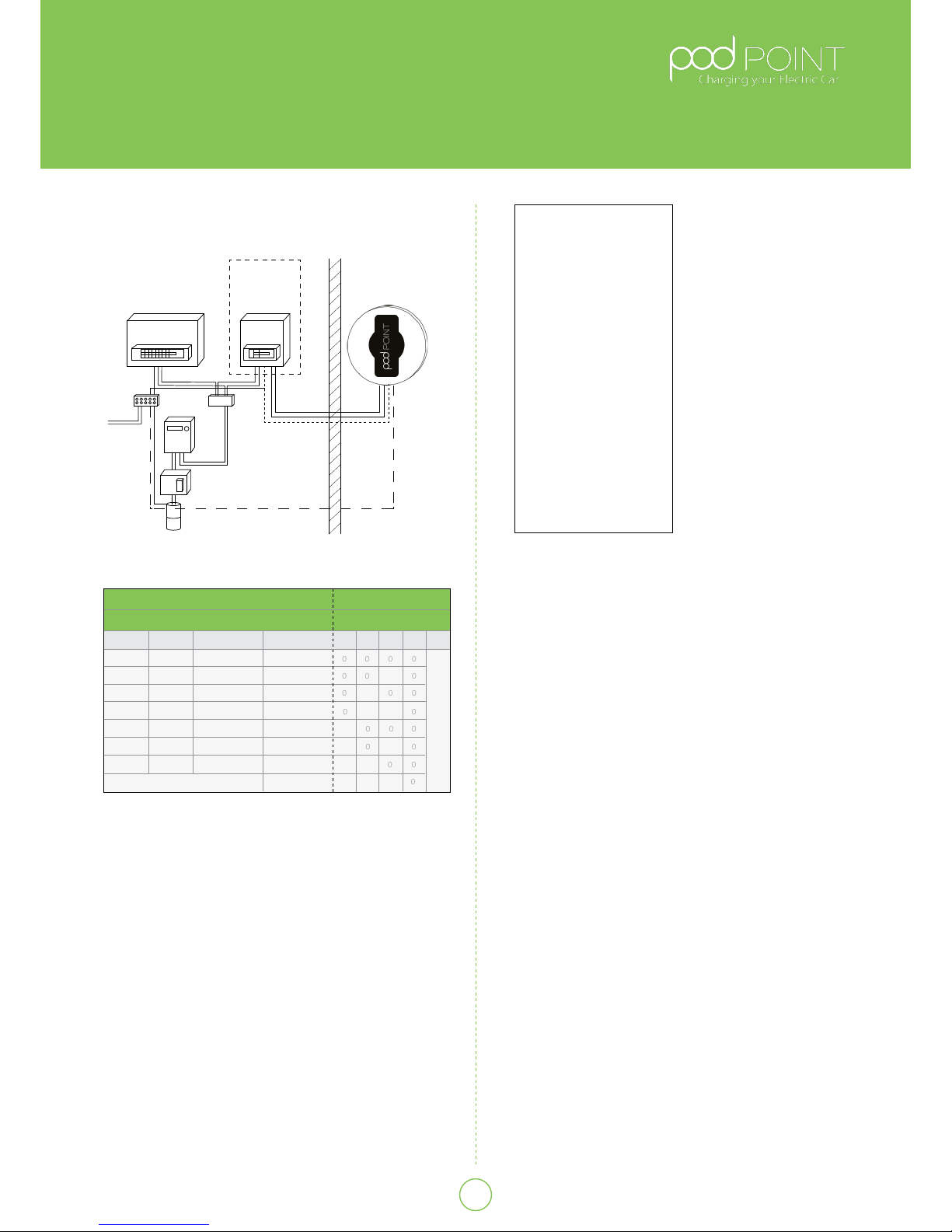
Isolation and Switching for Security
and Maintenance
To ensure that the POD Point Solo unit can be “turned o”
to enhance security and enable maintenance activity,
a double pole isolator (or 2 pole RCBO) suitably rated
must be installed within the customer’s property in an
accessible location. (See Table A) A dedicated isolator
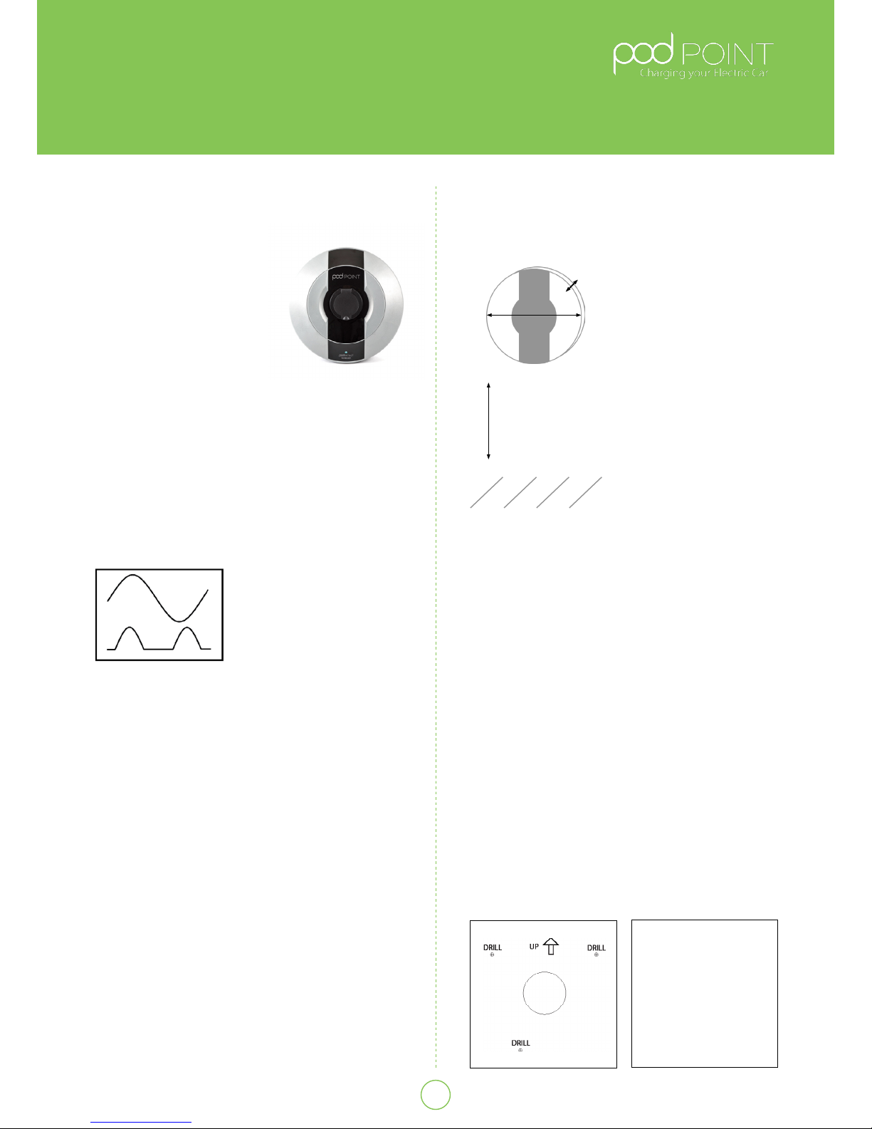
switch if tted should be mounted at a height of between
450mm and 1200mm above nished oor level to achieve
compliance with building Reg’s. A dedicated isolator
switch is a mandatory requirement for “new builds”, but
optional for existing dwellings (at customer’s request).
All installations must comply to current BS7671
regulations at the time of installation.
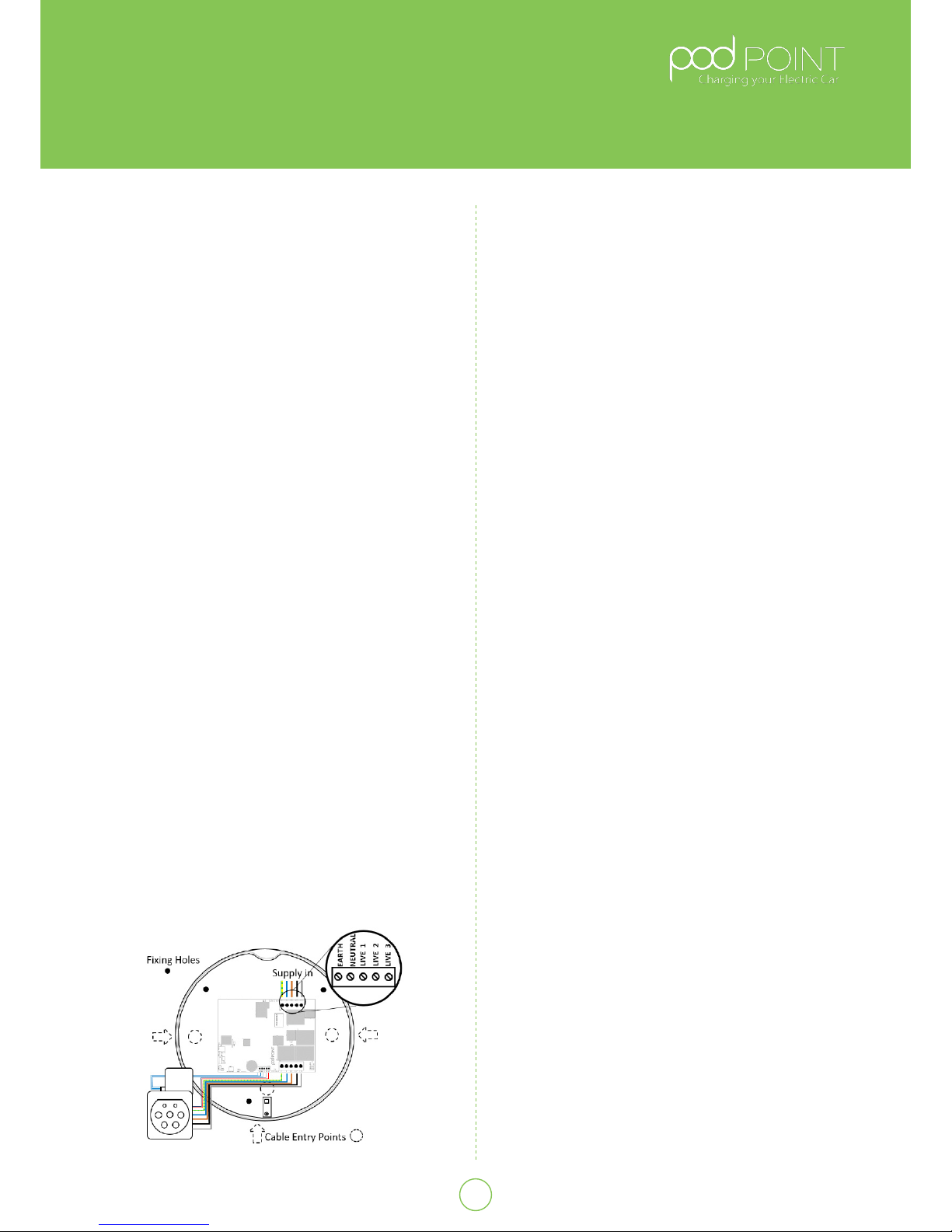
Wiring up the POD Point Solo
Fig.6
Solo Wiring Diagram
• With the rear unit securely tted to the wall, the
electrical supply connection can be made.
• As the installation route of the wiring will vary with
each Installation, allow enough cable for easy
termination and prevent the PCB terminals being
placed under strain.
• For socketed units allow adequate cable clearance
for the vehicle connector when assembled.
• The choice of entry point used will determine the
amount of insulation/SWA that needs to be
removed for connection of the unit. The diagram left
illustrates the connection terminals for the electrical
supply cables.
Ensure that power cables are connected to the
appropriate terminal as follows: (See Fig.6)
• Live 1: Brown
• Live 2: Black (3 Phase Units Only)
• Live 3: Grey (3 Phase Units Only)
• Neutral: Blue
• Earth: Green/Yellow
All of the cables that are to be connected into the supply
terminals should have their insulation stripped back
12~15mm to provide good contact to the screw terminals/
jaws, Recommended torque settings are 1.5~2.0Nm.
Before nal assembly, appropriate checks shall be
performed at the connections to conrm installation
integrity (pull test).
Connecting to Wi- network
On power up of the POD Point Solo the LED’s on the front
should illuminate white.
To connect the unit to a Wi-Fi network:
Obtain the customers SSID and WiFi password key (usually
found on the WiFi router) or let the customer complete a-c:
1. Scan for podpoint Wi- network on a mobile device
and connect to it.
2. Open the web browser and type the ip address:
192.168.1.1 followed by enter.
3. Complete the following information on the page
displayed on the device:
a. SSID name of the network the POD Point
Solo Is to connect via:
b. Type of encryption of this Wi- network.
c. Password of this Wi- network.
4. Press “Add” button located at the bottom of the web page.
5. Power cycle the POD Point Solo and wait for 1 minute.
Light should go blue with a short magenta ash. If the
LED remains white, you may need to power cycle the
unit again and verify the settings.
NOTE: the Pod Point connects to a secure server, all data
is encrypted using a unique algorithm.
3
Pod Point Solo Unit
Installation Guide
Pod Point February 2017
PP-D-130012-13
Pod Point Connecting Wi-fi Network Guide