manuals.online logo
Brands
  1. Home
  2. •
  3. Brands
  4. •
  5. POD Point
  6. •
  7. Batteries Charger
  8. •
  9. POD Point SOLO User manual

POD Point SOLO User manual

Introduction
This guide is intended for
use by competent electrical
installers to explain the
basic requirements and
options to be considered
when installing a Pod Point
Solo Mode 3 electric vehicle
charging point. The Pod
Point Solo is designed for
installations in or outside, the
advanced safety systems
we have built in to the unit
ensure its safe usage,
this guidance provides information to assist when
installing the new Pod-Point Solo. This guide should not
be used for any other EVSE as they do not include these
safety systems.
Important safety information
Warning! The Pod Point Solo charging unit is
manufactured to be safe and without risk provided
they are professionally installed, used and maintained
in accordance with the manufacturer’s instructions
and recommendations and installed by competent
electrical installers in accordance with national and local
regulations and legislation applicable at the time of
installation, e.g.: BS7671:2018.
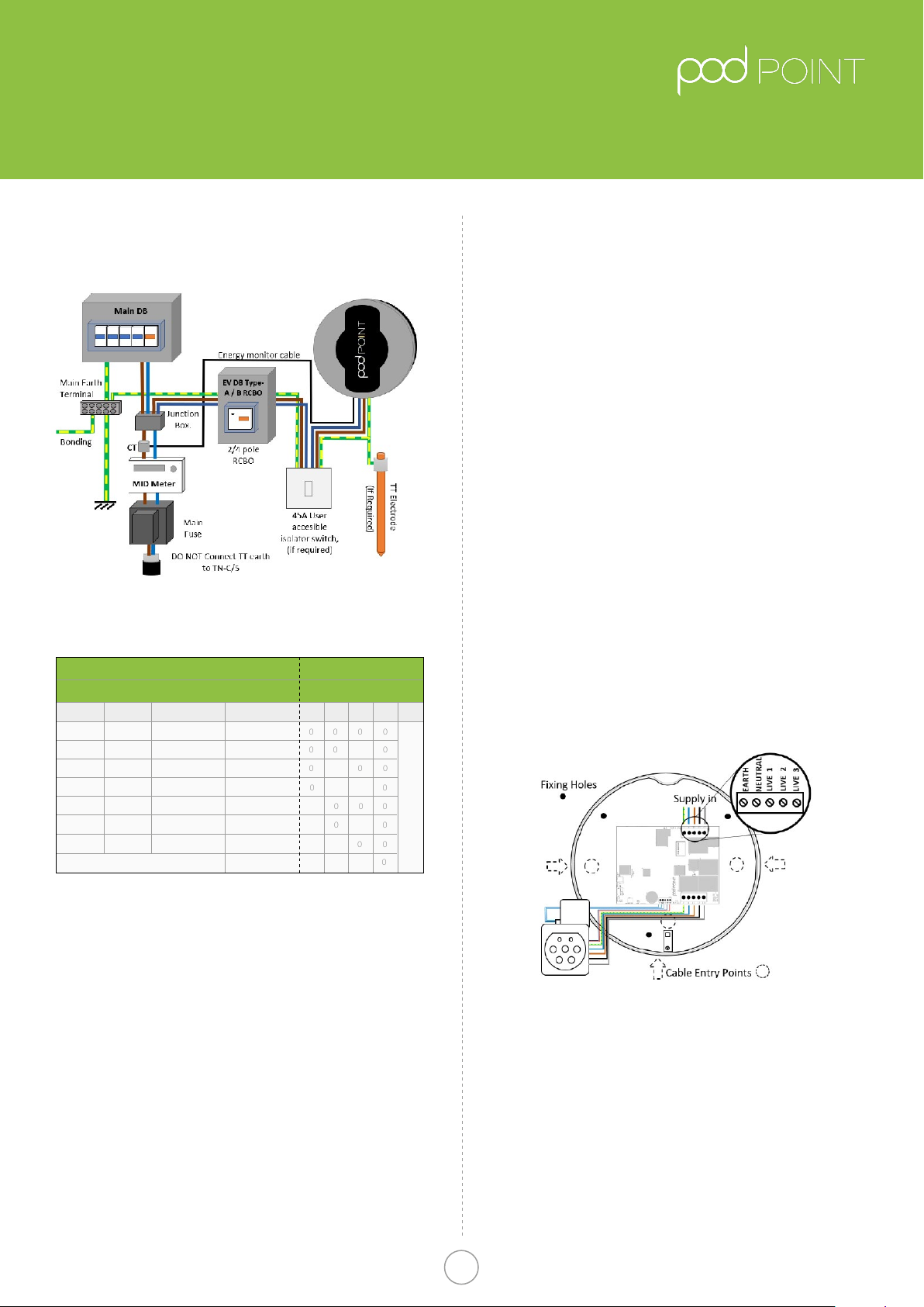
The Pod Point is designed to be connected to one
dedicated AC supply only. The property must comply
with minimum BS7671 standards before installation
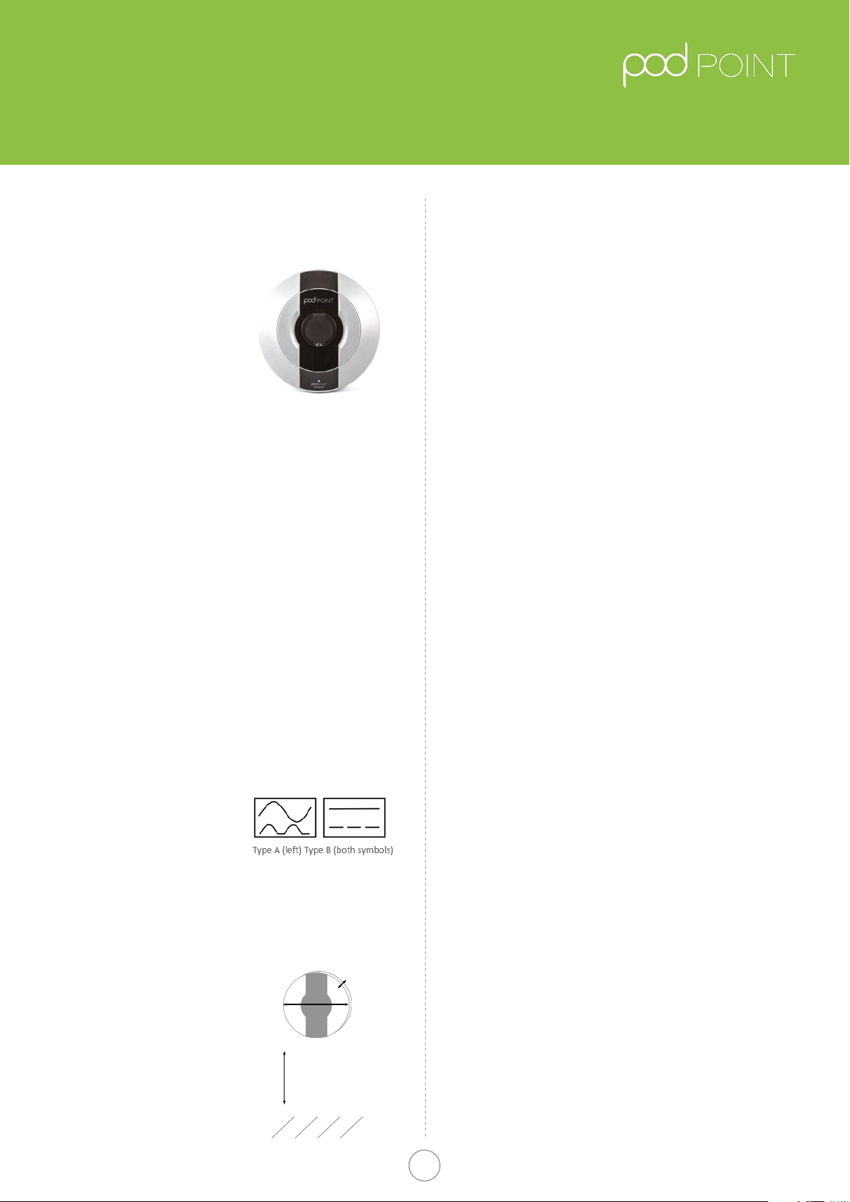
commences. As of the 1st January 2019 either a Type B
RCD must be used or a Type A with 6mA DC protection
included in the Pod-Point (see detail on packaging to
determine what protection is required),
Important note: A DC leakage
fault in the vehicle may “blind”
a type “AC” RCD and render
it ineective, never feed
any EVSE from an existing
upstream Type “AC” RCD.
Locating the Pod Point Solo
The Pod Point can be tted
inside or outside, the installer
should consult the EV owner
to establish their preferred
installation location. This should
take into consideration the cable
length (distance to vehicle being
charged), risk of vehicle impact
and obstruction of access etc.
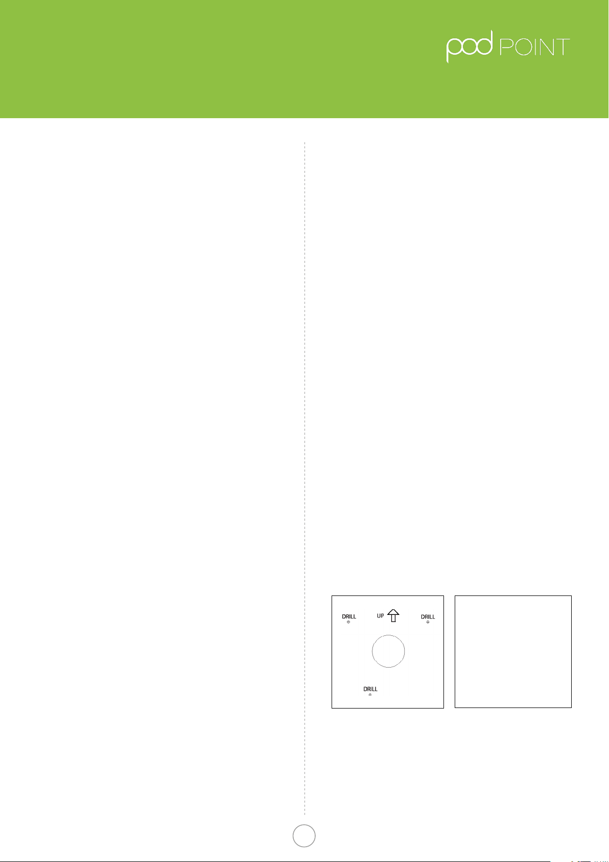
It is recommended the
Pod Point be mounted at
a height of 750mm-1.2m (
Fig. 2 ), (Building regulations
BS8300:2018 recommends
450~1200mm, BS7671:2018
recommend 500~1500mm).
Technical details
The Point Solo is designed to meet the following
European standards: IEC61851-1 edition 3 (2017), Low
Voltage Directive (LVD) 2014/35/EU and EMC Directive
2014/30/EU. During manufacture each Pod Point has
been functionality tested for safety using BS EN 61010
& BS EN 61557 approved equipment. The Pod Point Solo
is a Class I/II rated device for 230V / 400V AC 50Hz
systems and is IP54 rated. This installation guide is in
accordance to the latest BS7671: 2018.
Earth arrangements
The new Pod Point Solo features an on-board safety
monitoring system to detect low voltage supplies and
potential earth-neutral faults, If such a condition is
encountered the charge cycle is ended or prevented and
the Pod-Point eectively becomes a double insulated
(class II) device. The vehicle becomes isolated from the
incoming supply and poses no risk to touch.This feature
removes the requirement for an earth electrode where
it may be ineective or introduce further risk. The Pod
Point Solo unit (tethered or socketed) may be connected
directly to a TN-C-S (PME) earthing system without any
special arrangements, the new Pod Point solo complies
with regulation 722.411.4.1 (iii) of BS7671: 2018.
It remains the responsibility of the installer to conduct
a risk assessment of the immediate area to a range
of 10 Meters (equipotential zone) to ensure no other
conductive metal xings pose risks (mixture of TT/TN-S
and TN-C-S), this is important where cable length may
enable charging inside or outside of a building/garage
where the vehicle is within touch distance.
Where certain conditions dictate an earth electrode
must be used it shall be independent from the
distributors earth system with no direct interconnection
(the incoming supply SWA protective earth should be
isolated from the housing and/or earth electrode).
The electrical installer shall install a suitable electrode
complete with termination housing and covers where
appropriate, warning labels should be visible and close
to the unconnected SWA protective earth (e.g inside the
Pod-Point).
The earth connection shall be made from the electrode
to the Pod Point Solo via copper conductor earth wire
of an appropriate CSA for the installation. The earth
wire shall be installed in conduit where there is a risk of
mechanical damage or UV exposure.
* Note 1: Unless SWA is used, if a cable passes through
any metallic material (signage etc..) this will also require
bonding to earth, see separate documentation supplied
with Pod-Point signage if included.
* Additional note: Pod Point recommend Earth electrode
impedance to be < 100 ohms.
Pod Point Solo Unit
Installation Guide
Pod Point Solo -
Universal Version
Pod Point January 2019
PP-D-130012-14
Pod Point Solo Install Guide 1
750mm - 1200mm
365mm
150mm
Depth
Fig. 2
Dimensions and location of
unit (150mm depth)
Fig. 1
RCD Markings
RCD protection:
From January 2019 new Pod-Point’s will include
6mA DC vehicle fault protection and only Type A RCD/
RCBO’s are required at source, if the Pod-Point was built
earlier than this Type B RCD protection should be tted
at source, the symbols printed on the RCD in gure 1 can
be used to identify the type of RCD protection.
Surge protection:
Guidance on requirements for surge protection
devices given In BS7671: section 443.
The Pod-Point is protected against transient over
voltages (+/-2kV Line-Earth and +/-1kV Line-Line as a
requirement of EN 61000-6-1), a direct lightning strike
carries a current of 30~ 200kA the Pod Points internal
protection would provide little or no protection in such an
event, likewise nor would an SPD rated less than 30kA. If
life support equipment or business operations could be
aected by a lightning strike central SPD protection is
advised if it does not already exist. The guidance on risk
calculation in section 443.5 of BS7671 in most cases is not
possible due to unknown location of any SPD already
tted, length of cables to calculate Lp etc., it Is therefore
recommended a common sense approach is used on
choice of SPD (or if required).
Array systems:
The Pod-Point array system is designed to maximise
charging for several units connected to a limited supply,
To notify the Pod-Point of the total supply load a low
voltage signal provided by an array controller should be
hardwired to the point (connected to CON9 or J201). The
Pod-Point(s) require WiFi connection and commissioning
to enable the array features. For more details see:
https://d3h256n3bzippp.cloudfront.net/Solo-Pod-Point-Array-
Charging-Datasheet.pdf
Transformers
If a galvanically isolated transformer is required, it should
be placed upstream of the EVSE. The Neutral output
feed of the transformer shall be connected to EVSE
earth (creating a TN-S system). the PE taken before
any RCD and MCB (if 2 pole MCB is used), resistance
measured between the EVSE PE and this Earth must be
less than 100 ohms. Do not connect the output earth/
neutral of the transformer to a PME earthed system.
Upstream transformer RCD protection maybe of Type
AC (if tted), downstream RCD protection is still required.
Transformers should be rated for 100% duty cycle at 10%
above rated charge current and should be located in a
dry well ventilated area.
Direct EVSE connection to an IT system is prohibited.
Isolation and switching for safety and
maintenance
To ensure that the Pod Point Solo unit can be “turned o”
to enhance security and enable maintenance activities,
a double pole isolator (or 2 pole RCBO) suitably rated
must be installed within the customer’s property. An
isolator switch is a mandatory requirement for “new
builds”, but optional for existing dwellings (at customer’s
request), the switch should be mounted at a height of
between 500mm and 1500mm above nished oor level
to comply with regulation’s. The switch should be rated
at 45 amps.
All installations must comply to BS7671: 2018 regulations.
Installation procedure
The Pod Point Solo has been designed as a wall
mounted device. The installer should conrm that the
wall that the unit is intended to be xed to is structurally
appropriate for the mounting of the Pod Point Solo. The
installer should identify the construction of the wall, and
identify the correct and appropriate xings to use.
• The Installer has a duty of care to ensure that the
Pod Point Solo unit is securely attached to the wall or
structure where the unit is intended to be operated from.
• Once the location and height of the Pod Point Solo
unit has been decided, the installer can begin marking
the wall with indicator points to locate the unit. Us the
back of the box insert as the drilling template for the 3
mounting holes (Fig. 3)
• NOTE: If any groundworks are required (cable
trenching or earth electrode tment) it is advisable
to check if underground services could be present
before commencement, plans maybe available at:
linesearchbeforeudig.co.uk (free to domestic users).
Fig.3 Drilling template (box insert)
• Before drilling commences ensure that the installation
wall has been checked for electric cabling or pipework
with a suitable detector.
• It is highly recommended this is done prior to any
installation work commencement (drilling or tting of
conduit etc) to allow the customer to visualise where
the unit will be once installed. Once the installation site
is marked up, conrm with the customer this meets
their expectations.
Pod Point Solo Unit
Installation Guide
Pod Point Solo Install Guide 2
Additional parts required by
the installer:
1. 3x M8 80mm screws
2. 3x Wallplugs
3. 20mm IP56 or greater
gland for the conduit
entry into the rear unit
housing dependent on
the supply method
(20mm conduit, SWA
armoured cable, exible
conduit etc.).
Pod Point January 2019
PP-D-130012-14
Drilling the holes for the electrical
supply cable entry
As the electrical supply to the Pod Point Solo may be fed
from a number of directions; the unit has been designed
to accept supply cable entry on either the left, right,
bottom or via rear entry “knockouts” The installer should
drill a suitable size hole for the cable and grommet/
gland to be used. Cable entry holes should not be
drilled on any curved surfaces as this may provide an
entry point for water. 20mm “Rear Knockouts” are also
provided, water tight ttings should be used. Cable entry
at the top of the unit is strictly prohibited.
When drilling the case:
1. Only drill in the at surfaces provided on the left, right,
bottom or rear of the unit. Do not drill on any curved
surface.
2.Take care not to damage any wiring or components
inside the case. Place a suitable stop (e.g. block of
wood) inside the case when drilling to prevent
accidental damage.
3. If any of the wiring or components are damaged
during installation DO NOT CONNECT OR SWITCH ON
THE POWER before consulting with Pod Point.
4. The wall can now be drilled for the 3 mounting holes,
Do not drill with the Pod Point in position as masonry
dust may cause latent damage to the unit.
5. The Pod-Point can now be tted to the wall, depending
on the wall structure solid/dry lined or stud partition,
appropriate xings must be used to secure the unit.
6. Once tted in place, the rear unit should be securely
xed ush to the wall.
Wiring up the Pod Point solo
Fig.5
Solo Wiring Diagram
• With the rear unit securely tted to the wall, the
electrical supply connection can be made.
• As the installation route of the wiring will vary with
each Installation, allow enough cable to allow easy
termination so that the cable terminals are not under
strain.
• The choice of entry point used will determine the
amount of insulation/SWA that needs to be
removed for the internal wiring connection of the unit.
The diagram above illustrates the connection terminals
for the electrical supply cables.
Pod Point Solo Unit
Installation Guide
Pod Point Solo Install Guide 3
Table A.
Circuit protection and Power rating settings
Fig 4.
Typical Schematic of installation circuit
*The Pod Point also provides internal over-current protection in addition
to the above
Cable CSA
Power Rating
1Phase
3.1kW
2.4kW
1.4kW
MCB * / RCBO Switch Setting
13Phase 432
6kW
4.8kW
3.7kW
Pod Disabled
7.2kW
9.4kW
7.2kW
4.3kW
18kW
14.4kW
11kW
21.6kW
16A
16A
10A
32A
32A
20A
40A
1.5mm2
0
0
0
1
1
0
1
1
0
0
0
0
1
1
0
1
0
1
0
1
0
0
0
0
0
0
0
0
1 1 1
0
6mm2 - 10mm2
4mm2 - 6mm2
2.5mm2 - 4mm2
2.5mm2
2.5mm2
4mm2 - 6mm2
Unit Power RatingCircuit Protection
5**
Position depends on socketed/tethered
0=OFF, 1=ON
**Switch 5 OFF for socketed units
Switch 5 ON for tethered units
Pod Point January 2019
PP-D-130012-14
Ensure that incoming cables are connected to the
appropriate terminal as follows:
Live 1: Brown
Live 2: Black ( 3 - Phase Units Only )
Live 3: Grey ( 3 - Phase Units Only )
Neutral: Blue
Earth: Green/Yellow
All of the cables that are to be connected into the supply
terminals should have their insulation stripped back
12~15mm to provide good contact to the screw terminal
jaws, Torque settings for these connections is 1.5Nm.
Appropriate pull tests shall be performed at the unit
connections to conrm the installation is sound.
Smart energy monitoring
If energy monitoring of the domestic supply is required
an external current clamp should be connected to the
“blue” screw terminal block (CON9 or J201), Connect
the 2 clamp wires to GND and EXTC (external clamp),
the current clamp should be tted to the main input
supply cable close to the domestic energy meter. If the
maximum supply limit must be changed commissioning
over WiFi is required.
Final electrical testing
To meet the BS7671 (18th edition) requirements for
testing of an electrical installation, the following tests
and checks shall be performed by a competent electrical
installer before during and after a POD Point Solo unit is
installed:
• A visual inspection of the installation including the
existing electrical installation.
• Verication of the characteristics of the electrical
supply at the origin of the installation to conrm the
supply is suitable for the additional load.
• A test to conrm the continuity of the circuit protective
conductors.
• A test to conrm the integrity of the circuit insulation
resistance.
• A test to conrm the polarity of the installation is
correct.
• Where applicable a test to conrm the earth electrode
resistance is within acceptable tolerances (or)
• An earth loop impedance test
• Atest of the mechanical operation of residual current
devices (RCD’s)
• A test to conrm the operation of residual current
devices (RCD’s) is within stipulated timescales (at the
rated current and at ve times the rated current
operating current.)
• A test or calculated measurement of the prospective
fault current.
• A verication of the functional operation of the Pod
Point Solo unit. An electrical installation certicate must
be completed.
Connecting to Wi- network
https://s3-eu-west-1.amazonaws.com/podpoint-
website/Connecting-your-Pod-Point-Solo-to-Wi.pdf
QR Link to wi setup guide
On power up of the Pod Point Solo the LED’s on the front
should illuminate in white. To get the unit connected to
the Wi-Fi network do the following:
1. Search for “podpoint” Wi- network on your mobile
device and connect to it (no password needed).
2. Open a web browser on your device and type
192.168.1.1 in the address bar.
3. When the page has loaded select the desired Wi
network from the list and type in the password for
that network.
4. Press “connect” button located at the bottom of the page.
5. Power cycle the Pod Point Solo and wait for 1 minute.
Light should go blue with a short magenta ash when
connected.
6. If the status LED remains white, you may need to
restart the unit again and or verify the settings.
Fitting the front of the unit
Once the rear unit has been tted, the wiring to the unit
connected and tested, the front cover can be tted in
place. Prior to tting the front cover, visually check the
internal connections, remove any debris that may have
entered the unit during installation and check that the
front cover mating seal is in place. Place the cover on
the housing, using the top xing as a point of reference,
the front cover can then be secured in place at 5 points.
The unit is supplied with both pozidrive and T15 pin torx
screws if additional security is required.
Important information
Pod-Point do not authorise the use of ANY In cable
adaptors, charging cables used should not have any
modications made to them. If there is evidence of
damage to the charging connector(s) or cable it should
not be used for safety reasons.
For units with Type 2 socket, the charge cable must
be able to be fully inserted or charging will not begin
(socket must lock).
Pod Point Solo Unit
Installation Guide
Pod Point Solo Install Guide 4Pod Point January 2019
PP-D-130012-14

Other manuals for SOLO

2

Other POD Point Batteries Charger manuals

POD Point Solo Smart Charger Instruction Manual

POD Point

POD Point Solo Smart Charger Instruction Manual

POD Point SOLO User manual

POD Point

POD Point SOLO User manual

POD Point Solo Smart Charger User manual

POD Point

POD Point Solo Smart Charger User manual

POD Point PP_2111 User manual

POD Point

POD Point PP_2111 User manual

POD Point Twin User manual

POD Point

POD Point Twin User manual

POD Point Solo S3-1C User manual

POD Point

POD Point Solo S3-1C User manual

POD Point Solo Smart Charger Domestic User manual

POD Point

POD Point Solo Smart Charger Domestic User manual

POD Point Solo 3 - Home User manual

POD Point

POD Point Solo 3 - Home User manual

Popular Batteries Charger manuals by other brands

ANSMANN POWERLINE 5 PRO manual

ANSMANN

ANSMANN POWERLINE 5 PRO manual

Fein ALG80 quick start guide

Fein

Fein ALG80 quick start guide

Opticon CHG-3101 quick start guide

Opticon

Opticon CHG-3101 quick start guide

PowerTech MB-3690 instruction manual

PowerTech

PowerTech MB-3690 instruction manual

PRACHT ALPHA XT NRG1002 manual

PRACHT

PRACHT ALPHA XT NRG1002 manual

XINDAO XD P308.79X manual

XINDAO

XINDAO XD P308.79X manual

Shell SBC100 user guide

Shell

Shell SBC100 user guide

CAMBRIONIX PowerPad15C user manual

CAMBRIONIX

CAMBRIONIX PowerPad15C user manual

PowerXtreme XC3 user manual

PowerXtreme

PowerXtreme XC3 user manual

Muchmore Cell Master PT-CTXC Operation manual

Muchmore

Muchmore Cell Master PT-CTXC Operation manual

NDS SMARTCHARGER SCM25 user manual

NDS

NDS SMARTCHARGER SCM25 user manual

Milwaukee M12 48-59-1204 Operator's manual

Milwaukee

Milwaukee M12 48-59-1204 Operator's manual

Lester 18710 T operating instructions

Lester

Lester 18710 T operating instructions

Halo2Cloud Pocket Power 9000 operating instructions

Halo2Cloud

Halo2Cloud Pocket Power 9000 operating instructions

iOttie iON Wireless Stand Operation manual

iOttie

iOttie iON Wireless Stand Operation manual

Ravpower RP-SH015 user guide

Ravpower

Ravpower RP-SH015 user guide

Mobee Magic Charger quick start guide

Mobee

Mobee Magic Charger quick start guide

Beta 1498/24 Instructions for use

Beta

Beta 1498/24 Instructions for use

manuals.online logo
manuals.online logoBrands
  • About & Mission
  • Contact us
  • Privacy Policy
  • Terms and Conditions

Copyright 2025 Manuals.Online. All Rights Reserved.