●Check the mechanical operation of the residual
current device, including the rated trip current and
at five times the rated current.
●A test or calculated measurement of the
prospective fault current.
●Functional verification using an EV simulator
confirming operation of the Solo 3.
●If a vehicle is available, check the vehicle charges
normally for a short time.
●If the Pod Point EV simulator is available, test fault
state and DC 6mA functions of the Solo 3.
Note: At the time of this document’s publication, there are no
specific standards for 6mA DC testing. If ramp tests are
conducted, false readings are possible if the test equipment
has too fast a ramp up time (Max trip time @6mA = 10 Sec).
When checking internal safety systems of the Solo 3,
disconnection of the vehicle/tester may be required to reset
these systems.
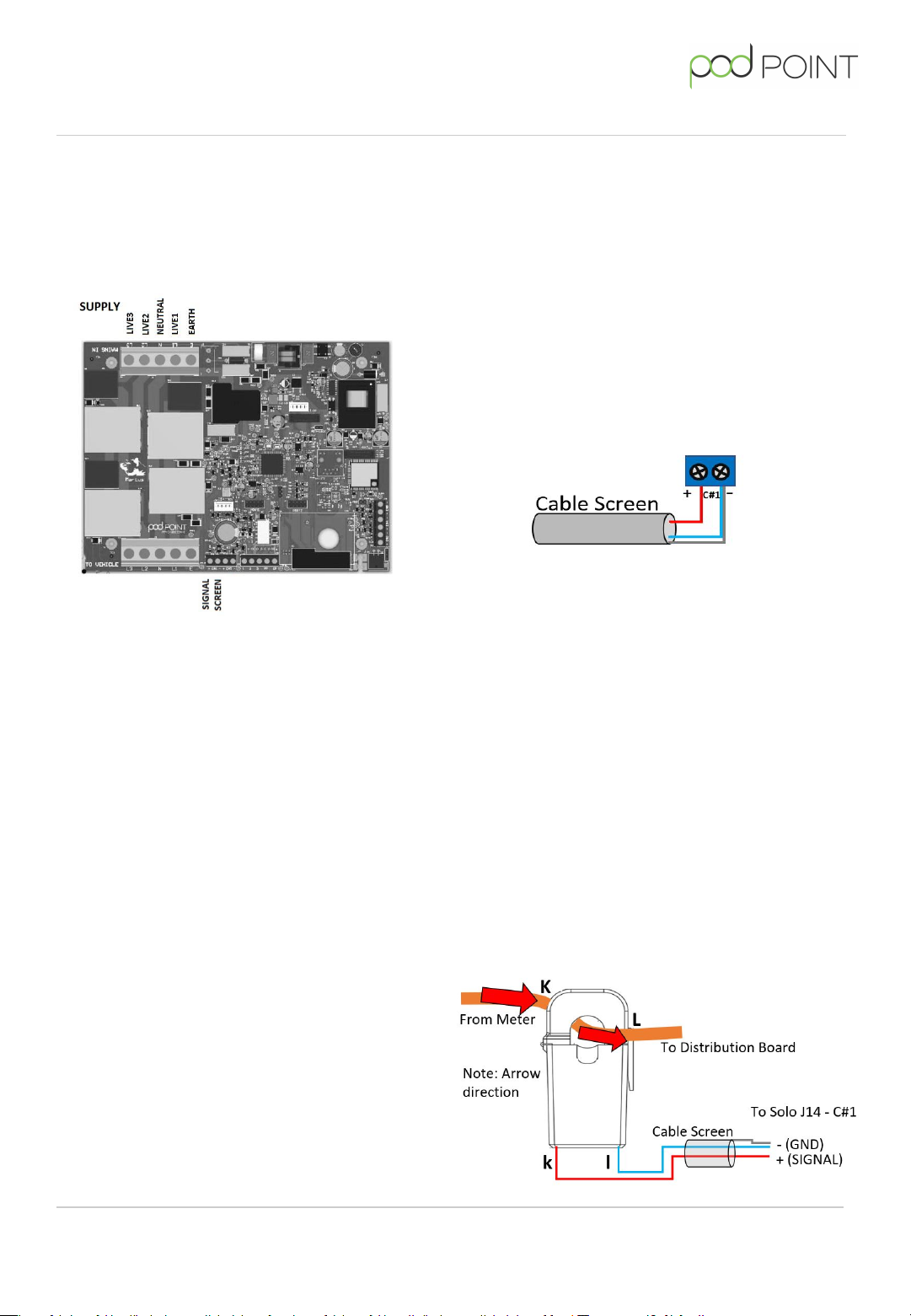
Energy clamp Test.
If relevant connect the Energy Clamp to J14 - C#1 and
measure the resistance between the positive and
negative terminals. The resistance should be around
74 ohms. If less than 10 ohms you have a short circuit,
if greater than 80 ohms you have an open circuit
between the PCB and the energy clamp.
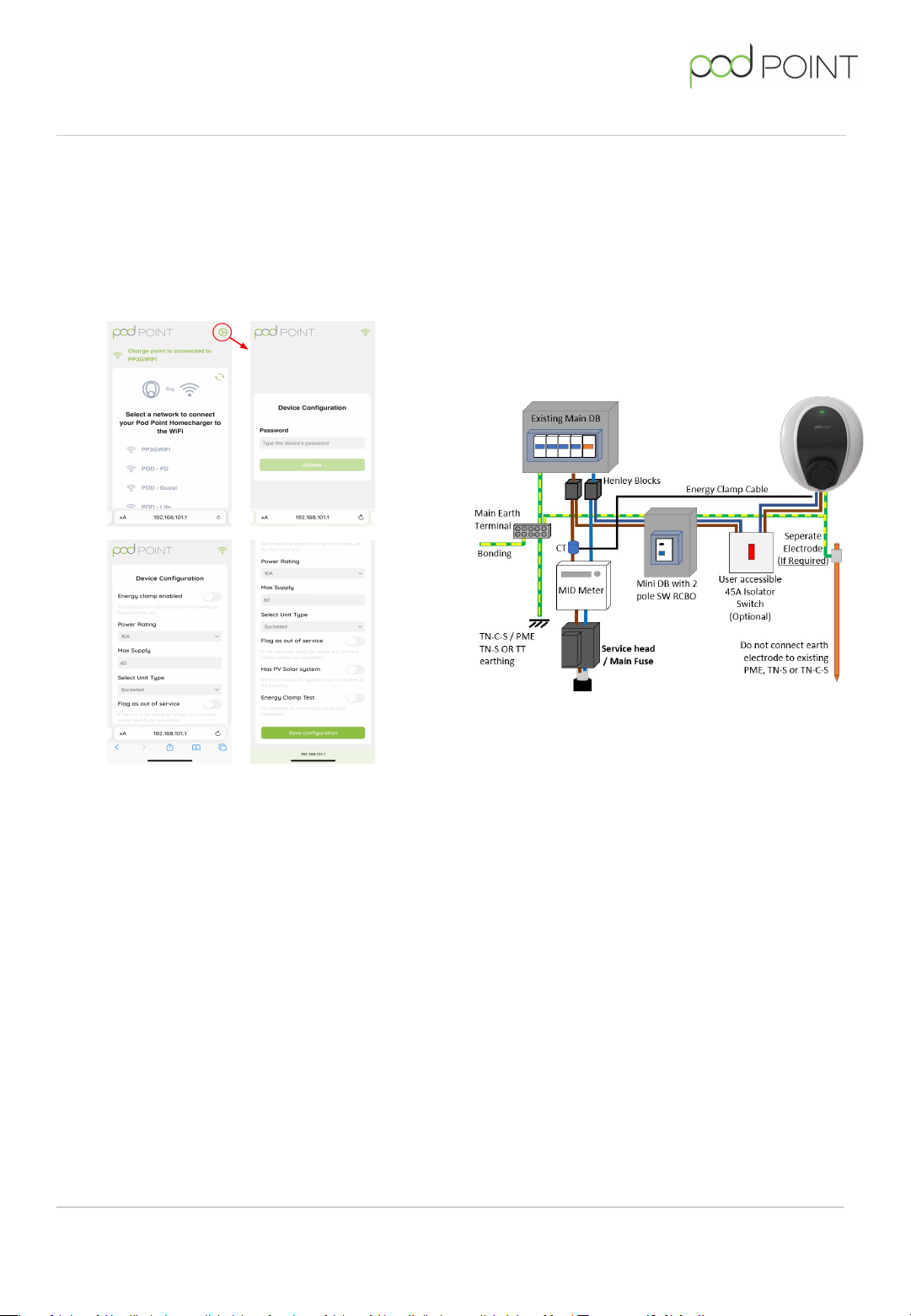
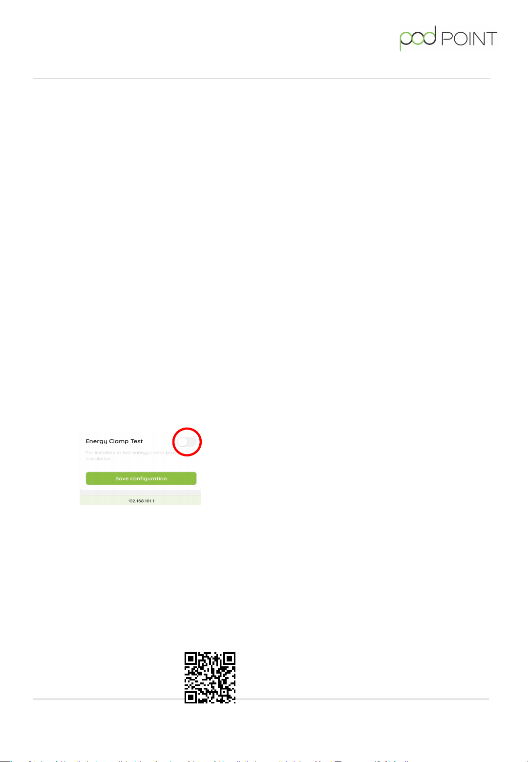
To enable Energy Clamp test mode visit the AP
webpage 192.168.101.1, toggle ‘Energy clamp test’ on
and lastly save configuration.
Disconnect the Energy clamp form the tail or from the
connector on the PC and plug the Pod Point EV
simulator into the Solo 3 and the heater into the EV
simulator socket. In state C the Solo 3 should fault if
the Energy Clamp is operating correctly. To conclude
this test access the AP webpage, disable ‘Energy
Clamp Test’ and save the configuration. Reconnect the
Energy Clamp and ensure the Solo 3 does not fault in
State C.
Connecting the Solo to Wi-Fi
Visit Pod Point's installation documents webpage to
get to our
Pod Point Solo Wi-Fi Connection Guide
Scan this QR code to get to
our installer documents
webpage - you’ll find
the connection guide here.
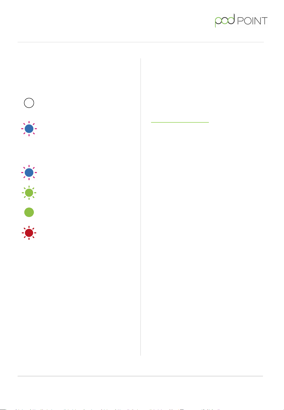
On power up of the Solo 3, the front LED should
illuminate white. To connect the Solo to a Wi-Fi
network do the following:
●Search for “podpoint” Wi-Fi network on your mobile
device and connect to it.
●On the device’s web browser address bar type
192.168.101.1 then “Enter” or “OK”.
●A page displaying available networks should show.
Select the desired network and enter the network
password. Press “Connect” at the bottom of the
page.
Note: The page will remain displayed but inactive after
“Connect” has been pressed.
●Wait for 1 minute. The LED should change to blue
with a short pink flash when it has connected.
●If the status LED remains white, you may need to
restart the Solo 3 again and verify the settings (see
notes at end of this guide).
Fitting the front of the charger
Once the wiring, testing and setup of the Solo 3 is completed,
the front cover can be fitted in place.
Prior to fitting the front cover, visually check the internal
wiring will not interfere with assembly, dress if needed, and
remove any debris that may have entered during installation.
Check that the front cover mating seal is in place before
fitting the cover to the housing. The front cover can then be
secured in place using the 6 screws.
Accessories, features and helpful hints
Remote diagnostics
When connected to the internet via Wi-Fi, the Solo 3 will
provide information on supply voltage(s), status of the
incoming earth, charging current, temperature, rating of
connected cable, etc. This data is primarily used for internal
diagnostic purposes but is also used for energy usage
displayed in the Pod Point App. In exceptional circumstances,
Pod Point may contact the site/charger owner if an
abnormality is detected.
Key lock
The Solo 3 may include a mechanical key lock feature to
disable use of the charger where theft of electricity is a
concern. The key lock input requires “volt free” isolated
switching contacts. When the contacts are closed, the Solo 3
enters a “Pause” state and the LED will flash yellow.
Theft of the Solo 3
All Solo 3 EVSE includes a unique MAC address to identify
itself which is programmed into the silicon and cannot be
changed. If a Solo 3 is reported as stolen and its connection
to the Pod Point network is attempted, it can be placed
permanently out of service.
Solo 3 - Home
Solo 3 - Home PP-D-210449-2
Install Guide S3-UK-H-IG