POD Point Twin User manual

Fast Charging
Twin Charger
Install Guide (Web Version)
Twin Charger
Installation Guide PP-D-150133-4
T-C-UK-IG
Twin Charger PP-D-210456-3
Installation Guide

Pod Point is not responsible for installation and/or commissioning works
performed by a 3rd party
In the absence of any negligence or other breach of duty by Pod Point, Pod Point is not
responsible for any injury, loss or damage caused by any works, services, products or
equipment provided or performed by the customer or a third party (and not by Pod Point or
a party for which it is responsible) in relation to the installation and/or commissioning of the
Twin Charger.
If the installation and/or commissioning of the charger is not performed by Pod Point, it is
the customer’s responsibility to ensure that any third party appointed to install and/or
commission the Twin Charger is appropriately qualified and does so in compliance with all
applicable regulations and with reference to the guidance provided in this document (and
associated documents linked within). Pod Point provides this guidance as a reference only
and it is not a substitute for the appointment of competent persons to carry out installation
and commissioning.
Do not open, move, modify, rewire, tamper or interfere with your Twin Charger
once it has been installed.
The customer must ensure that an installed Twin Charger is not opened, moved, modified,
re-wired, or otherwise tampered or interfered with, without first referring to Pod Point’s
latest technical guides and/or notifying Pod Point directly and complying with Pod Point’s
recommendations.
Please also see the charger’s applicable warranty terms which may be aected by taking
such action. If you have any concerns in relation to a Pod Point that has already been
opened, moved, re-wired or otherwise has been tampered or interfered with, please notify
Pod Point directly so that appropriate advice can be provided, noting that Pod Point
assumes no responsibility for your installation by virtue of providing such advice.
In the absence of any negligence or other breach of duty by Pod Point, Pod Point is not
responsible for injury, loss or damage caused by the Twin Charger being opened, moved,
modified, re-wired or otherwise tampered or interfered with by the customer or a third
party (and not by Pod Point or a party for which it is responsible).
Legal Notice
Before reviewing this installation guide, please read the following information carefully.
PP-D-210456-3
Twin Charger
Installation Guide (Web Version)
2

Twin Charger
This symbol is used throughout this guide to indicate a warning. Failure to follow these
warnings could result in failure of the equipment, personal injury or result in the
warranty being void.
This symbol is used throughout this guide to indicate danger. Failure to follow the
instructions within this guide could result in personal injury or electric shock.
Safety Instructions
●This product must only be installed and maintained by suitably qualified and competent
persons.
●Pod Point recommends using only Pod Point authorised and instructed engineers for
installation and maintenance services. Failure to do so may invalidate the product’s warranty -
please see our Warranty Terms and Conditions for more information.
●Installation and maintenance work should be carried out in accordance with the current
version of BS 7671 and any other national or local regulations, legislation or guidance
applicable at the time of installation. Please follow the IET Code of Practice for Electric Vehicle
Charging Equipment Installation.
●It is the responsibility of the person(s) carrying out the installation work to ensure all
instructions and methods described in this guide are followed at all times.
●Pod Point cannot accept any responsibility where:
○this installation guide has not been followed
○applicable regulations and guidance has not been followed
○the installation is performed by someone who is not suitably qualified or competent.
●Standards, specifications and designs change from time to time. Information contained within
this guide may be subject to change without notice. It is the installer's responsibility to ensure
the latest instructions, standards, specifications and designs are being followed.
●To ensure electrical safety, this product must be maintained in accordance with
recommendations made in this guide.
●This product must not be adapted or modified in any way, doing so could result in personal
injury or damage to the product and connected equipment or cabling. Adaptations,
modifications or other unauthorised interference with the product may void your warranty.
Please see our Warranty Terms and Conditions for more details on this.
●Physical damage to the product may result in unsafe conditions, ensure electricity supplies are
isolated and the product is not used if damaged - consult Pod Point for further information
and repair.
DANGER! Hazardous Voltage - Never make any unauthorised modifications to the
internal components of this product. Ensure that the supply to the Twin Charger is
isolated and locked o before installation and maintenance activities are carried
out.
3
PP-D-210456-3
Twin Charger
Installation Guide (Web Version)

Twin Charger
Technical specifications T7 Single Phase Models T22 Three Phase Models
Charge Protocol EV supply equipment intended for Mode 3
charging EV supply equipment intended for Mode 3
charging
AC Operating Voltage 230v AC 50Hz (per socket) 400v AC 50Hz 3P+N (per socket)
Rated Insulation Voltage 500VAC 400VAC
Rated impulse Voltage 4kV 4kV
Nominal Current 32A (per socket)
64A (combined) 32A (per phase per socket)
64A (per phase combined)
Rated conditional short-circuit current ≤ 75 000 A2s ≤ 75 000 A2s
Power Output Up to 7kW (per socket) Up to 22kW (per socket)
Earthing system TT, TN-S, TN-C-S TT, TN-S, TN-C-S
Internal RCD Protection Type A 30mA (BS EN 60947-2) per socket Type A 30mA (BS EN 60947-2) per socket
Internal DC Leakage Protection Internal 6mA DC detection
(IEC 62955) per socket Internal 6mA DC detection
(IEC 62955) per socket
Internal Overcurrent Protection Internal C40A, 10 kA, 2 pole MCB
(BS EN 60898) per socket Internal C40A, 10 kA, 2 pole MCB
(BS EN 60898) per socket
Upstream RCD Protection Required in some circumstances Required in some circumstances
Protection against electric shock
Pollution Degree
Overvoltage category
Class I*
Pollution degree 3
Category III
Class I*
Pollution degree 3
Category III
EMC classification Class A (Immunity)
Class B (Emission) Class A (Immunity)
Class B (Emission)
Cable Terminal Capacity Copper Cable Min 6mm² - max 25mm²Copper Cable Min 6mm² - max 25mm²
IP (Ingress) Rating IP54 IP54
IK (Impact) Rating IK10 IK10
Environnemental use Indoors and Outdoors with non-restricted
access Indoors and Outdoors with non-restricted
access
Operating temperature -25°C to 40°C -25°C to 40°C
Height
Width
Depth
1330mm
241mm
295mm
1330mm
241mm
295mm
Weight 19kg (19.3kg with RFID) 22.5kg (22.8kg with RFID)
*When not in charge mode the vehicle is galvanically isolated from the supply.
Product support
You can find the latest installation & technical guides on our website at: www.pod-point.com or
via the QR code.
If you have any further questions, comments, or issues regarding Pod Point Products which are
not covered by this installation guide, please try our help centre (help.pod-point.com) or
contact our customer support team. You may be asked to provide the serial number of your
Pod Point Twin Charger (located at the bottom of the charger).
4
PP-D-210456-3
Twin Charger
Installation Guide (Web Version)

Product overview
The Twin Charger has been designed specifically for commercial applications to provide a reliable
and easy to use fast charging solution - available as single phase 7kW and three phase 22kW
variants.
The Twin Charger is compliant with the UK Smart Charge Regulations which requires a number of
features to be implemented to ensure the charger is secure and the users data is protected. For
more details please refer to https://pod-point.com/guides/smart-charge-point-regulations
The Twin Charger incorporates a number of electrical components and features to ensure safe
operation for the user. Internal 30mA type A RCDs are inbuilt (per socket) which conform to BS EN
60947-2, these devices provide earth leakage protection to the socket outlets and any vehicles
connected to them, each RCD is electronically resettable by manual intervention - removing the
vehicle connector and reattaching. 6mA DC earth leakage protection is inbuilt (per socket) to allow
the use of type A RCDs both within the Twin Charger (RCDs in the supply circuit will need to be
specified in accordance with details provided on page 9 & 10) - this feature will disconnect the
electricity supply to the vehicle in the event of DC earth leakage exceeding 6mA which in turn will
prevent unintentional blinding of type A RCDs and ensure safe operation.
Internal supply monitoring ensures that the protective earth conductor is intact before allowing a
charge cycle to start, these monitoring systems will detect an open PEN conductor condition in the
supply network and disconnect the electricity supply to the vehicle - the electricity supply will only
be reinstated once the supply network returns back to normal parameters and the vehicle
connector has been disconnected and reattached. This monitoring system allows the Twin Charger
to be safely connected to a PME earthing system.
The Twin Charger is capable of load limiting which can be set at commissioning stage. If the Twin
Charger is installed as part of an Array system, active load balancing is activated ensuring the total
installation capacity is not exceeded.
What's in the box & unpacking
The Twin Charger package will include:
❏Twin Charger - in specified variant
❏Foundation surface mount (separate box)
❏Ingress protection foundation seal
❏Fixings
❏Installation Guide
Remove the packaging carefully and set the Twin Charger, ingress protection foundation seal and
surface mount aside. Recycle the product packaging where possible, check the contents of the
packaging before proceeding with the installation - if anything is missing, please contact us
immediately.
Twin Charger
5
PP-D-210456-3
Twin Charger
Installation Guide (Web Version)

Tools Required
Specialist tools required for safe installation:
Security torx bits
- Pin Torx T30 (upper door)
- Pin Torx T45 (lower door and ground level fixing)
Torque calibrated tools
- Torque screwdriver for electrical connections
- Torque wrench for foundation fixings
Pre installation checks
Before starting the installation, please confirm the following:
●A suitable power source has been made available taking into consideration the power
requirements of the Twin Charger being installed - design of the electrical installation should
only be carried out by a suitably trained and competent person.
●The proposed site has been selected in order to minimise the risk of damage to the Twin
Charger and to ensure the Twin Charger can be used correctly.
●Twin Charger Connectivity
Your Twin Charger must communicate with our servers in order to:
- Validate it’s Warranty
- Receive over-the-air updates and functionality improvements
- Enable remote maintenance and asset monitoring
- For you / the hardware owner to control access, taris and provide usage insight data
Before commencing installation you should determined which communication type your
installation will utilise:
1. 3G/4G Mobile connectivity
2. Wi-Fi only
Please note:
When using Option 1;
- The presence of a 3G/4G router is determined by “-RO” at the end of the product SKU
on the box and/or Twin Charger.
- When using mobile connectivity only 1 Twin Charger in 5 will require a Router providing
the Twin Chargers are sited in adjacent parking bays i.e. within c.25m of uninterrupted
line of sight. The remaining 4 Twin Chargers will be able to link with a Wi-Fi hotspot
created by the Twin Charger with a Router.
When using Option 2;
- A good quality WiFi signal must be available(2.4GHz only) - additional AP(Access
Points) may be required to strengthen signal
- Twin Chargers will lose communication if the Wi-Fi password is changed, Wi-Fi contracts
are not paid etc - this loss of communication remains the Landlord / Owners
responsibility
Twin Charger
6
PP-D-210456-3
Twin Charger
Installation Guide (Web Version)

Twin Charger
7
PP-D-210456-3
Twin Charger
Installation Guide (Web Version)
Groundworks
The surface mounting foundation adapter is used to secure the charger to the foundation. A
purpose laid 600 x 600 x 400mm (WxHxD) level concrete pad must be used to mount the adapter -
fixing to tarmac, block paving or other surfaces is not recommended.
The surface mounting plate is secured to the ground using four M10 x 120mm minimum expanding
countersunk concrete anchor bolts (or preferred equivalent fixing).
Supply cables are to be routed into the bottom of the charger ensuring the duct is centralised to
allow the ingress protection foundation seal to be fitted correctly. The maximum duct size is 110mm.
The Twin Charger and associated signage should not obstruct the pavement or other public
footway. Under no circumstances should the width of a public footway be restricted to less than
1m, preferably not less than 1.5m.
Fig 2. Surface Mount
Fig 2. Shows the Twin Charger foundation mount and its orientation.

The installer is responsible for ensuring that the earthing system used is adequate and meets the
requirements detailed within the current version of BS 7671.
Further checks pursuant to BS 7671 should be made when the Twin Charger is connected to a TT
earthing system. An RCD will always be required at the source of supply where a TT earthing
system has been used - either for the whole installation or locally for the charger only, our
recommendations for the type of RCD can be found on page 8, 9 and 10.
Where a RCD is providing protection to more than one vehicle connector socket outlet, cumulative
DC leakage currents should be considered - Please ensure compliance to BS 7671 (722.531.3) is met.
Further technical & earthing systems Information can be found here:
Pod Point Earthing
Systems Guidance
Earthing Arrangements
The Twin Charger must be connected to a permanent, metallic earthing system in accordance with
the current version of BS 7671 and any other applicable local and National regulations.
The Twin Charger is suitable for connection to the following earthing systems:
Twin Charger
The Pod Point Twin Charger has built in PME fault protection which means it can be connected to
a PME (TN-C-S) earthing system 1
1 PME fault protection is disabled when the Twin Charger forms part of an Array system.
Electrical connection
Cables being terminated to the Twin Charger must be done so to avoid unintentional damage -
appropriate cable glands must be used at the point of entry to the cable connection enclosure
(DBOX), cables must be stripped to the correct length to avoid excess copper showing at the
termination. Terminations must be tightened within the specified torque of:
2.5 Nm
Cables must be correctly identified by colour within the connection enclosure (DBOX).
TN-C-S (PME) TNS TT*
8
PP-D-210456-3
Twin Charger
Installation Guide (Web Version)

Fig 3. Initial Configuration of DBOX
single-phase three-phase
Electrical connection
Start by carefully removing the access door
from the rear of the charger (note the door
is connected to the main charger body via
an earth cable - please ensure this is not
strained or damaged). The Distribution Box
(DBOX) is located towards the bottom of the
charger with a see-through lid. Unscrew the
lid and safely set aside, unscrew & remove
the lower Gland Plate in preparation for
installation of the cable gland(s).
The gland plate will need to be drilled to fit
an appropriate sized gland(s) for the
incoming cable(s) to enter through.
It is essential that incoming supply
cables are correctly glanded and
secured into the charger to ensure
the safety of the product is
maintained.
Once the gland plate has been drilled and an
appropriate gland fitted, re-attach the Gland
Plate to the bottom of the DBOX in
preparation for the installation of the supply
cable(s).
Both single and three-phase Twin Chargers
come pre-configured for single supplies (1
supply circuit providing power to both
charging sockets) this can be adjusted for
dual supply installations. The Twin Charger
connection points within the DBOX will
initially be configured as in Fig 3.
Twin Chargers specified with an RFID and/or
Router, will be supplied with a 12V aux power
supply, this will be pre-installed inside the
DBOX. You will not need to do any additional
wiring for these variants, however for
reference the initial configuration will instead
be as in Fig 4. below:
Please now refer to the relevant wiring
instruction, T7 single phase or T22 three
phase.
Fig 4. Initial Config of DBOX (with 12V)
single-phase three-phase
Twin Charger
9
PP-D-210456-3
Twin Charger
Installation Guide (Web Version)

Single-phase (T7) Installations
Single phase T7 Twin Chargers require a 230V AC supply capable of supplying 32A per door. This can
be achieved using a Single Supply, Dual Supply (2x single phase circuits) or a Polyphase Supply (
2
phases of a three phase system and a common neutral
). Cables must be suitable for the installation
method chosen and be adequately protected against mechanical damage / stress. Circuits and
supply cables must be able to carry the nominal load current and combined prospective fault current
for the Twin Charger. The Twin Charger must be protected against overcurrent and fault at the
source of supply by a suitably rated MCB, MCCB or fuse (see below for current ratings).
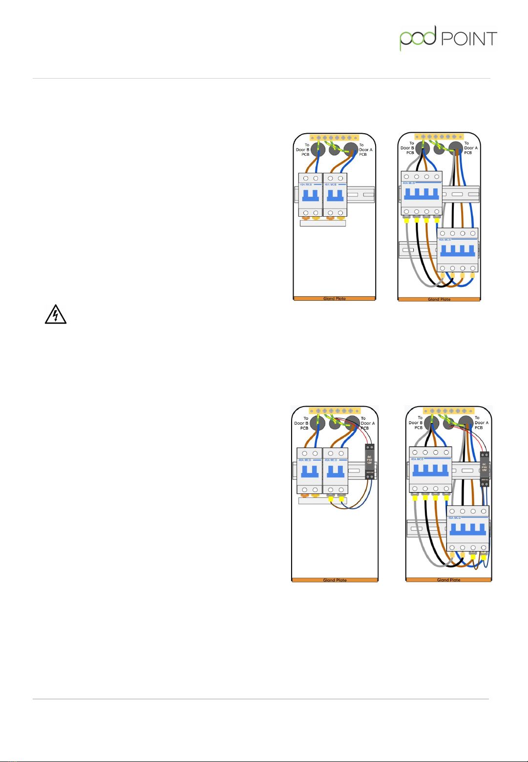
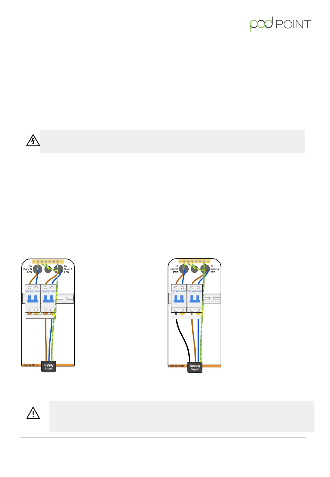
Single Supply (80A, 1 phase)
1x 3-Core Cable (1 phase + Neutral)
Route the supply cable
into the DBOX through
the cable gland. Install
the Live & Neutral
supply cables into the
cable terminals on the
Right side MCB (Door A).
These should be
pre-connected to the
Left MCB (Door B) via a
pre-installed 2-Pole
4-way Fork Busbar -
verify that the fork
busbar is correctly
connected. Connect the
CPC to the Earthing
terminal at the top of
the DBOX.
Single Supply - Polyphase (80A, 3 phase)
1x 5-Core Cable (2 phase + common Neutral)
Route the supply cable into the
DBOX through the cable gland.
Remove the pre-installed
2-Pole 4-way Fork Busbar,
remove the end cap and
remove the fork busbar rail
connecting the live terminals
together. Replace the end cap
and reinstall the busbar to link
the two neutrals together -
ensure the busbar has been
connected correctly. Install the
L1 & Neutral cables in to the
cable input terminals of the
right MCB (Door A), now install
the L2 cable into the left MCB
(Door B). Connect the CPC to
the Earthing Terminal at the
top of the DBOX.
Twin Charger
DANGER! If the Twin Charger is to be connected to a TT earthing system, an RCD
must be provided at the source of supply.
IMPORTANT! 5 core supply cable is recommended for a polyphase supply to
ensure a dedicated CPC identified by green & yellow sheathing is provided. Please
ensure spare conductors are safely terminated.
Where there is a requirement for a RCD to be fitted in the supply circuit, for example where a TT
earthing system is being used, it must be of time delayed type with a rating over >100mA to avoid
conflict with the in-built 30mA RCDs - for single supply and polyphase arrangements cumulative DC
leakage currents should be considered - Please ensure compliance to BS 7671 (722.531.3) is met.
For dual supply arrangements (individual circuit per charging socket) the RCD should be at least
type A - type AC RCDs must not be used.
10
PP-D-210456-3
Twin Charger
Installation Guide (Web Version)

Single-phase (T7) Installations - continued
Route the supply cables
into the DBOX through the
cable glands. Remove the
pre-installed 2-Pole 4-way
Fork Busbar. Connect the
first supply Live & Neutral
to the cable inputs of the
Left MCB (Door B). Then
connect the second
supply Live & Neutral to
the cable inputs of the
Right MCB (Door A).
Connect both CPC’s to the
Earthing Terminal at the
top of the DBOX.
Route the supply cables into
the DBOX through the cable
glands. Remove the
pre-installed 2-Pole 4-way
Fork Busbar. Connect the
designated supply cables
(circuit 1) to the input
terminals for Live & Neutral
of the Left MCB (Door B).
Connect the designated
supply cables (circuit 2) to
the input terminals for Live &
Neutral of the Right MCB
(Door A). Connect the CPC to
the Earthing Terminal at the
top of the DBOX.
Dual Supply (2x 40A, 1P)
2x 3-Core Cables 2x (1P + N)
Dual Supply (2x 40A, 1P)
1x 5-Core Cables 2x (1P + N)
Twin Charger
Three-phase (T22) Installations
Three phase T22 Twin Chargers require a 3 Phase + Neutral 400V AC supply capable of supplying 32A
per door. This can be achieved using a Single Supply or a Dual Supply (2x 3 phase supplies). Cables
must be suitable for the installation method chosen and be adequately protected against mechanical
damage / stress. Circuits and supply cables must be able to carry the nominal load current and
combined prospective fault current for the Twin Charger. The Twin Charger must be protected against
overcurrent and fault at the source of supply by a suitably rated MCB, MCCB or fuse (see below for
current ratings).
DANGER! If the Twin Charger is to be connected to a TT earthing system,
an RCD must be provided at the source of supply.
Where there is a requirement for an RCD to be fitted in the supply circuit for example where a TT
earthing system is being used, it must be of time delayed type with a rating over >100mA to avoid
conflict with the in-built 30mA RCDs - for single supply and polyphase arrangements the RCD must
be type B, for dual supply arrangements the RCD should be at least type A - type AC RCDs must
not be used.
Ensure 5 core cables have been identified as per the colouring scheme defined in
BS 7671 (514.4)
11
PP-D-210456-3
Twin Charger
Installation Guide (Web Version)

Three-phase (T22) Installations - continued
Install the Neutral, L1, L2
and L3 cables in to the
cable inputs of the top
MCB (Door B). These
should be pre-connected
to the lower MCB (Door A)
via a jumper loom in the
busbar inputs. Connect
the Earth Cable to the
Earthing Terminal at the
top of the DBOX.
Remove the pre-installed
jumper loom connecting the
inputs of Door A and Door B
MCBs. Then connect the first
supply to the cable inputs of
top MCB (Door B) and the
second supply to the cable
inputs of lower MCB (Door
A). Connect both Earth
Cables to the Earthing
Terminal at the top of the
DBOX.
Installation finalisation & checks
Following the installation of the supply cable(s) in accordance with the selected Twin Charger and
chosen supply wiring configuration, connect the Earth fly lead located in the bottom of the Twin
Charger chassis to the connection point on the foundation adaptor - this connects the chassis to the
Earthing terminal.
Carry out a post connection inspection of the charger, ensuring:
❏Cables and busbar links are located in the correct terminals
❏Cables and busbars links have been tightened to the specified torque setting
❏Supply cables have been installed using an appropriate cable gland
❏Supply cables are free from damage
❏Supply cables have been identified correctly
❏The Twin Charger has been fixed securely to the foundation
❏The ingress protection foundation seal has been fitted
NOTE: If the on-site supply capability is not adequate for an installation, the Twin Charger may be
remotely derated from 22kW to 11kW or 7kW to 3.6kW. If this is required, you will need to replace
the main decal sticker on the lid of the Twin Charger to indicate the true charging rate of 11kW or
3.6kW.
Twin Charger
Three-phase
Single Supply (80A) 3P + N
Three-phase
Dual Supply (2x 40A) 3P + N
12
PP-D-210456-3
Twin Charger
Installation Guide (Web Version)

Twin Charger
Electrical testing
Upon the completion of the installation or relocation of the Twin Charger, the installer must carry
out initial verification and testing of the supply circuit(s) as set out in BS 7671, Pod Point
recommends that the following additional tests are conducted with results recorded:
❏RCD tests (x1 and x5) on both vehicle connector sockets (A and B)
❏6mA RDC-DD (DC leakage) ramp test on both vehicle connector sockets (A and B)
❏Earth loop impedance (Zs) tests on both vehicle connector sockets (A and B)
Certification should be issued to the client upon completion of the installation.
Pre commissioning
Visually inspect the Twin Charger to ensure:
❏Supply cables are adequately glanded and secured into the charger.
❏There is no damage to supply conductors
❏Internal MCBs have been switched into the “ON” position
❏The DBOX cover has been refitted
❏Earth fly leads are securely attached
❏The ingress protection foundation seal is fitted correctly
Refit the rear access door, ensuring a small amount of anti-corrosion grease is applied to the door
fixing bolts.
Ensure the foundation ground plate is securely fixed with bolts / nuts tightened to the correct
torque value (see fixing manufacturer data), confirm that the foundation fixings have washers fitted
and that one of the methods below is being used to ensure the Twin Charger does not become loose
over time:
❏Thread locking compound applied to foundation threads
❏Nuts with Nylon insert used
❏Locking nuts used
❏Spring washers used
The Twin Charger can now be powered on ready for commissioning.
13
PP-D-210456-3
Twin Charger
Installation Guide (Web Version)

Commissioning of Twin Chargers
Visit the PP Install App to
commission this charger. If you
do not have access to the
Pod Point App, please visit:
pod-point.com/3rd-party-commissioning
Testing of Functionality
In order to test the functionality of the
sockets of the twin, the back door must be
fully closed to ensure the tamper detection is
not activated. If it is not fully closed you will
see a red flashing yellow sequence.
When power is turned on, lights on both sides
of Pod Point Twin Charger should change
colours as follows:
1. Establishing communication with server
(takes up to 1 min) - White
2. Communication established, car not
plugged - Blue flashing pink
An EV Simulator should then be plugged in to
both sockets and the Twin Charger’s
functionality should be tested as follows:
1. Unlock mode (State A) - Blue flashing pink
2. Standby (State B) - Flashing green
3. Charge (State C) - Green
4. Fault - Solid or Flashing Red
If the test procedure fails at any stage please
contact Pod Point.
Connecting to Wi-Fi
For installations including Twins with Routers,
the Twin Chargers should automatically
connect to the locally created Wi-Fi network.
Alternatively, to connect the Twin Charger to
a site Wi-Fi network follow the below steps:
1. Obtain the site’s Wi-Fi network SSID and
Wi-Fi password key (usually found on the
Wi-Fi router)
2. Switch 1 side of the Twin Charger on, by
turning on 1 out of 2 MCBs, while the other
one is turned o.
3. Scan for podpoint Wi-Fi network on a
mobile device and connect to it.
4. Open the web browser and type the IP
address: 192.168.101.1 followed by enter.
5. A page displaying available networks will
show. Select the desired network and enter
the network password. Press “Connect” at
the bottom of the page.
Note: The page will remain displayed but
inactive after “Connect” has been pressed.
7. Turn the power on and o if the
connection fails and wait for 1 minute.
8. Follow the same procedure to connect the
second side of the Twin to the Wi-Fi.
When a connection has been made, the door
LEDs should go blue flashing pink. If the LED
remains white, you may need to power cycle
the charger again and verify the settings.
NOTE: the Twin Charger connects to a secure
server, all data is encrypted using a unique
algorithm.
Twin Charger
General installation guide
documentation can be found
here:
14
PP-D-210456-3
Twin Charger
Installation Guide (Web Version)

Twin Charger
Maintenance
The Twin Charger requires ongoing maintenance to ensure it remains safe for continued use and to
ensure longevity. Maintenance tasks should only be carried out by suitably qualified and
competent persons.
Pod Point recommends that the internal RCDs within the Twin Charger should be
manually checked for operation every 6 months in line with recommendations within BS
7671 - this manual check should only be carried out by a suitably qualified and
competent person.
Pod Point recommends that the Twin Charger is inspected and tested at least every 12
months by a suitably qualified and competent person, these checks will ensure the
internal safety devices are operational - these tests apply to internal features only and
not any devices included in the supply circuit which should be tested in line with the
relevant Electrical Installation Condition Reporting (EICR) Schedule.
In very high use locations, it is recommended to increase the inspection frequency to
every 6 months. It is the responsibility of the installer to assess the requirement to
inspect more frequently than every 12 months and to notify the owner of the Twin
Charger accordingly.
Pod Point recommends using our authorised engineers for all inspections and maintenance
requirements. Failure to do so may invalidate the product warranty - please check the Pod Point
Warranty Terms and Conditions for more information on this. To arrange a service visit by a Pod Point
authorised engineer, please contact us via:
www.pod-point.com/contact
15
PP-D-210456-3
Twin Charger
Installation Guide (Web Version)

This manual suits for next models
2
Table of contents
Other POD Point Batteries Charger manuals

POD Point
POD Point PP_2111 User manual

POD Point
POD Point SOLO User manual

POD Point
POD Point Solo Smart Charger Domestic User manual

POD Point
POD Point Solo Smart Charger Instruction Manual

POD Point
POD Point Solo S3-1C User manual

POD Point
POD Point Solo 3 - Home User manual

POD Point
POD Point SOLO User manual

POD Point
POD Point Solo Smart Charger User manual