3.General warnings
4
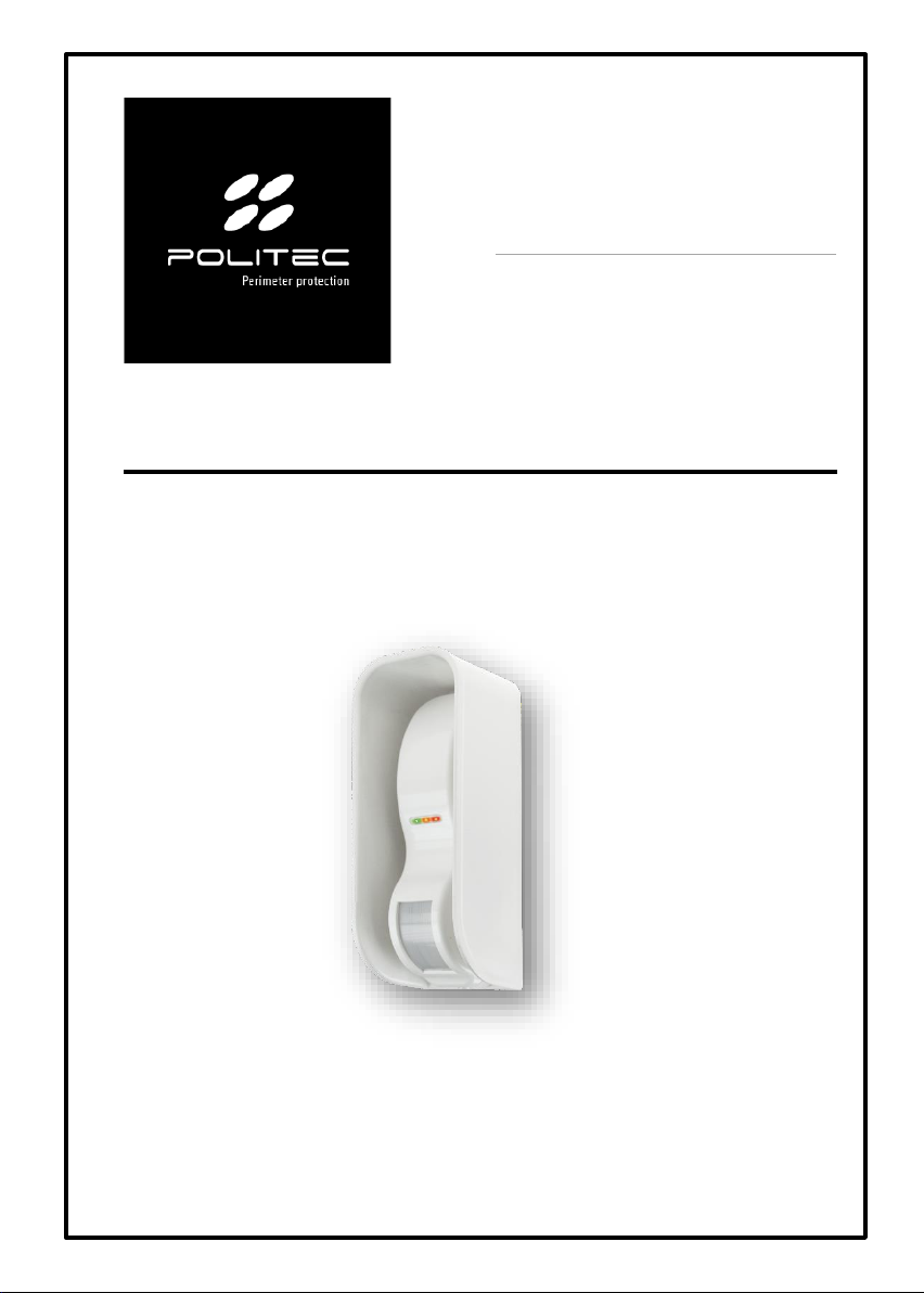
NAT SENSOR POLITEC | INSTALLATION MANUAL - VER.2.1
This installation manual contains important information regarding safety for installation: it is
necessary to read all the instructions before proceeding with the installation.
Keep this manual for future use.
•If you have any questions or doubts during installation, do not carry out any operations and contact
the support service.
•Use of these products for purposes other than those specified in these instructions is prohibited.
•You must not make any change to the components of the product unless stated in the manual in
order not to void the warranty; such operations can only lead to malfunctions; Politec assumes no
liability for malfunctions or damage due to modified products.
•Depending on the specific situation of use, check for the need for additional devices: detectors or
signalling devices.
•During installation, mounting and use of the product, make sure no foreign objects (solids, metals
or liquids) are able to penetrate inside the open devices.
•Manufacturer's liability:Politec assumes no liability for failures resulting from incorrect installation;
lack of maintenance, incorrect assembly or use.
•Politec is also not liable for incorrect or incomplete operation of the product or failure to detect
intrusion.
•Warranty (summary of conditions):Politec guarantees its products for a period of 2 years from the
production date.The warranty is applied to those purchasing directly from Politec; there is no
warranty for the end user who, in the event of breakdowns or faults, must contact the installer or
dealer.
•The warranty excludes aesthetic parts as well as parts subject to normal wear and parts subject to
normal consumption such as batteries and accumulators.
3.1 Additional warnings for devices powered by mains voltage
This manual is intended only for technical personnel qualified to install such devices.
•Assessing the hazards that may occur during installation and use of the system, in order to achieve
complete safety, it is necessary that installation takes place in full compliance with applicable laws,
methods, rules and regulations.
•Before accessing the internal terminals of the product, it is necessary to disconnect all the power
circuits.
•If automatic circuit breakers or fuses trip, before resetting them it is necessary to identify the fault
and repair it.
3.2 Installation warnings
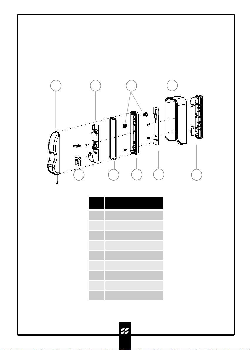
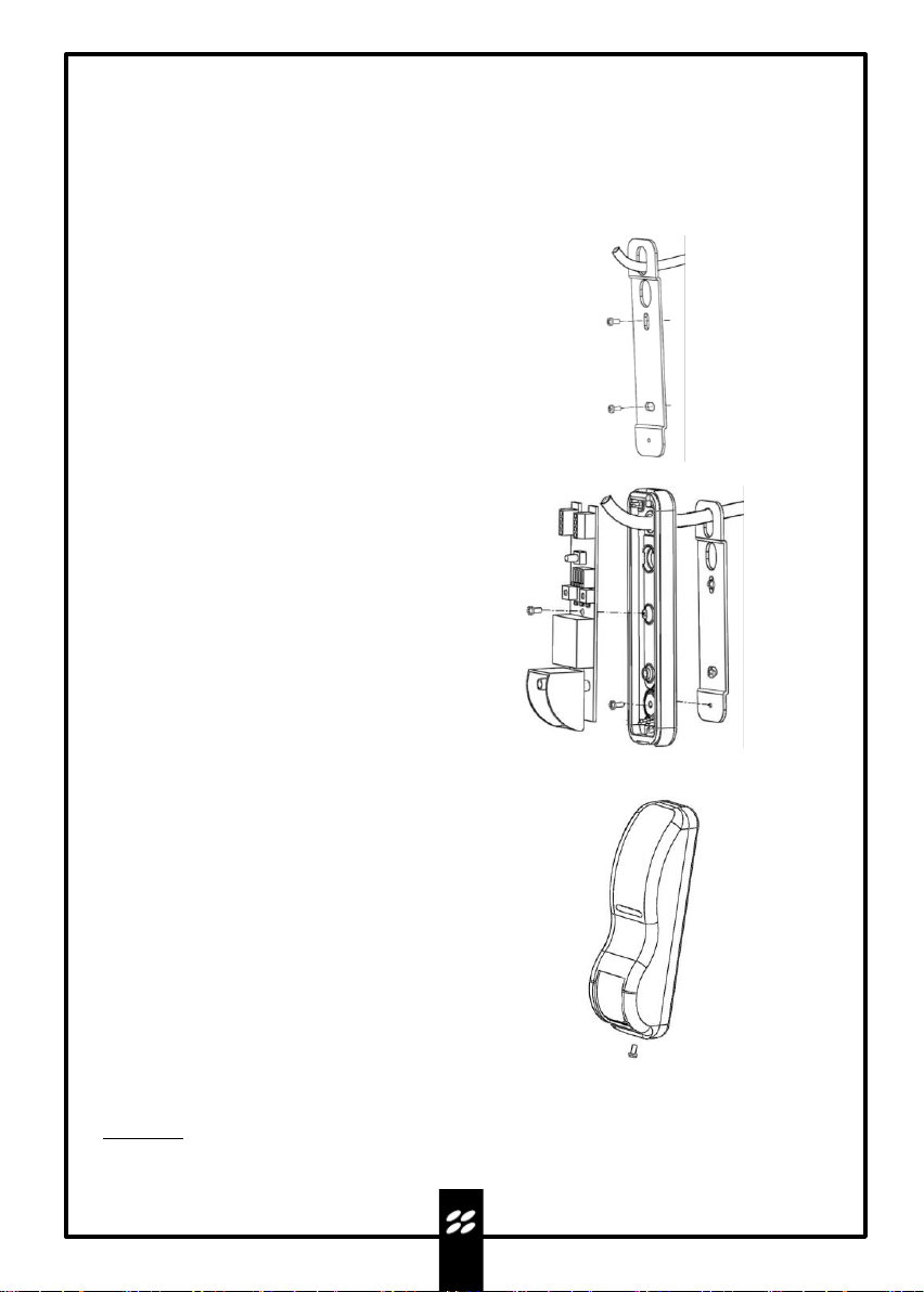
•Check that all the material to be used is in excellent condition and suitable for use.
•Before proceeding with the installation, check the environmental class of the products in the
"technical specifications" chapter.
•Check, comparing with the values shown in the paragraph "technical specifications", that the range
of the devices is correct
•Check that the sensor is positioned in areas protected against potential impact, in flat areas and on
fixed supports to avoid movements.
•Do not place the system components close to heat sources as they could be damaged.
•Each sensor has its own operating principle: check the instructions for choosing the right position in
the respective instruction manual.