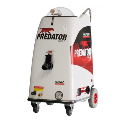
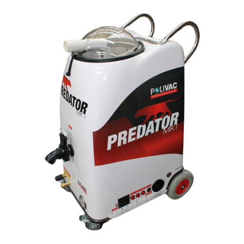
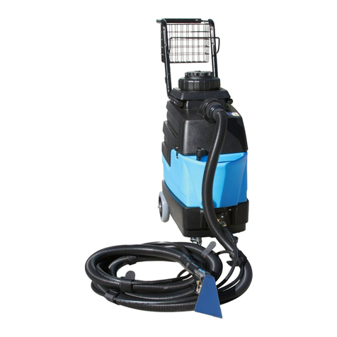
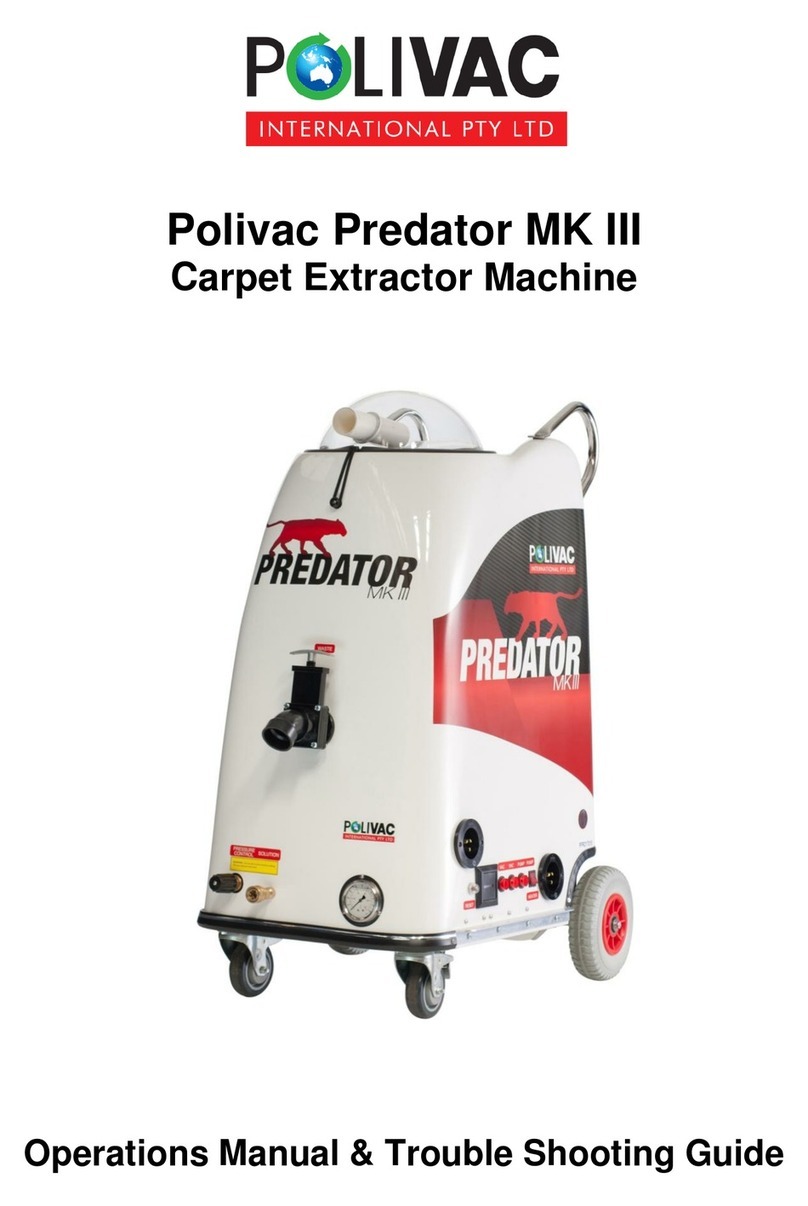
Polivac Predator MK II User manual

1
Polivac Predator MK II
Carpet Extractor Machine
Operations Manual & Trouble Shooting Guide

2
This is an introduction on the use of the Polivac Predator Carpet Extraction unit.
Directions for Use
1. Connect 240v extension cable from power source to #1 power socket on unit. Fig #1
2. Now connect the Male end of solution hose to Female solution outlet on the
front of the unit. Fig #2
3. Connect the Female solution end to the Male fitting on the trigger of the
steam cleaning wand.
4. Ensure dump valve and booster inlet are closed, if these are not in use. Fig # 3 & 4
5. Fill machine with either cold or hot water. We always recommend pre-spraying the carpet rather
than use of Chemical solutions and powders run through the machine, for a number of reasons, 1st
this gives better results as the chemical has had time to “work” on the carpets, 2nd when you extract
with fresh water, you remove more chemical residue which prevents re-soiling and chemical build up.
Finally it extends the life of your pump, the use of high alkaline chemicals can cause premature failure
not covered by warranty. NEVER USE FLAMABLE LIQUIDS OR SOLVENTS IN THE
STEAMCLEANER
6. The heater switch can now be selected and as power is connected the switch
will light up RED and this will commence the heater working. ` Fig #1
7. Water is now being heated up.
8. Connect the G Vac hose to the domes nose and the other end to the wand end.
You are now ready to clean!!

3
Polivac predator side control panel
1. 240 volt 10 AMP power inlet socket.
2. Pump or heater selector switch.
3. Water pump power switch.
4. Vac motor #1 power switch.
5. Vac motor #2 power switch.
6. Machines operating hour timer.
7. Thermal pump overload reset switch.

4
This is an introduction on the use of the Polivac Predator Carpet Extraction unit.
Operating the Polivac Predator
Now you have set the unit up according to the previous instructions it is time to engage the unit
completely.
Turn on the pump switch (3) and Vac 1 (4) and Vac 2 (5) as per Fig #1.
The machine will now be ready to work.
Set the required pressure by turning the pressure control valve (Fig #2); Clockwise motion will
increase water pressure and adversely counter clockwise will result in decreasing pressure.
Pressure gauge will reflect all movements of the pressure control but only while wand trigger is
engaged.
You are now able to commence work.

5
Polivac Predator pressure control
1. Pressure increase/decrease regulator tap.
2. Solution outlet (for connection to high pressure hose).

6
Polivac Predator Dump Valve
To release captured waste water lift handle as shown in diagram.
Water will drain & then depress the handle down to reseal.

7
Polivac Predator pressure Gauge
This gauge shows the operator what pressure the water is hitting the surface at. The Predator has a
range of 0 - 500psi.
The recommended carpet cleaning pressure is 350psi - 400psi . (Adjusting past this doesn’t provide a
better cleaning results, instead just causes unnecessary wear on wand triggers.)
Recommended upholstery tool pressure is 150psi.

8
Polivac Predator Booster inlet.
Figure 1 shows booster inlet in the closed position
Figure 2 shows inlet opened to connect the vac hose and booster box.
Inlet opens by hand only and will close itself after use.

9
General Maintenance & Troubleshooting Guide
Maintenance
The key to keeping the unit in good working order is general maintenance.
Follow the below procedure for best result with unit.
1. Water filter
Remove from water tank by unscrewing. Clean and refit.
2. Lint deflector
Remove screen from channel and remove all lint and dirt build up
3. Oil level
Check once a month.
4. Floor tool
Remove build up of lint from opening of tool.
5. Vac motors
No maintenance can be done but use Antifoam to prevent chemical and water entering motors and
causing faults.
Troubleshooting Fault Remedy
1. No Power to unit
Check power cable and power from source
2. Heater not working
Check pump/heater switch (Fig #1 #2) is switched to heater and not pump
3. Pump not working
Check pump/heater switch (Fig #1 #2) is switched to pump and not heater check thermal reset button
(Fig #1 #7) and depress to engage.
4. No water coming from floor tool
Check pump is running
Check water level is sufficient
Check floor tool jets for blockage
Check water tanks filter for blockage
5. Vac motors not working
Check both switches are on (glowing red)
Check dome lid is on correctly and sealing
Ensure waste dump valve is complete shut

Predator MKII & MKIII
Drawings by: LeanSynergicDesign.com.au
Cabinet Assembly
42
35
27
28
8
9
11
29
1
14
11
13
22
24
6
7
11
10
21
12
19 30
15
23
16
31
35
34
25
11
26
31
20
18
19
17
11
33
32
22
29

Predator MKII & MKIII
Drawings by: LeanSynergicDesign.com.au
No Code Description
1 PPR001 Cabinet
2 PPR028 Dump Valve
3 PPR030 Gasket
4 PPR029 Dump Valve Spout
5 PPR031 Nut
6 PPR027 Dome
7 PPR047 Rubber Seal
8 PPR002 Continental Trim
9 PPR049 Vent Grill White
10 PPR114 Dome Latch
11 PVT029 Screw
12 PPR014 Handle Assembly
13 PPR035 Float
14 PPR012 Filter Track
15 PPR013 Filter Screen
16 PPR113 Float Guide
17 PPR177 Screw
18 PPR104 Washer
19 PPR096 Nut
20 VLB608 Rubber Washer
21 PPR103 M8 x 30 mm
22 PPR135 Loop
23 AAA500 Screw
24 PVS037 Nut
25 PVT018 Piano Hinge
26 AAK838 Rivet
No Code Description
27 PPR003 Pinch Weld
28 PPR005A Switch Guard Alloy
29 PPR245 Polivac Label
30 PPR128 Washer
31 PVT025 Washer
32 PPR090 Bolt
33 AAA354 M6 Nyloc
34 PPR212 Screw
35 PPR095 M4 Nyloc
Cabinet Parts List

Predator MKII & MKIII
Drawings by: LeanSynergicDesign.com.au
Motor-Pump-Frame Assembly
9
38
4
6
17
16
18 19 20
10
8
9
2
1
39
36
35
33
34
30
37
21 23
39
15
15
8
32
24
31
9
11
22
26
27
13
12
14
28
29 40
41
42
25
PPR257
8
7
43

Predator MKII & MKIII
Drawings by: LeanSynergicDesign.com.au
No Code Description
1 PPR005 Side Frame
2 PPR009 Wheel Plate
3 PPR006 Front Frame
4 PPR007 Rear Frame
5 PPR010 Cross Bar
6 PPR008 Motor Plate
7 PPR016 Castor
8 PPR090 Bolt
9 AAA354 Nut
10 PPR017 Drive Motor
11 SK006 Bolt
12 AAG365 Washer
13 SLB043 Nut
14 PPR011 Axle
15 PPR093 Bolt
16 PPR015 Tyre
17 AAG480 Washer
18 PPR128 Washer
19 GAS045 Spring Washer
20 GAS049 5/16'' x 3/4'' Set Screw
21 PPR018 Pump
22 Part of PPR018
23 Part of PPR018
24 PPR056 Brass Plug
25 PPR055 Brass Plug
26 Part of PPR018
Motor-Pump-Frame Assembly Parts List

Predator MKII & MKIII
Drawings by: LeanSynergicDesign.com.au
Motor-Pump-Frame Assembly Parts List
No Code Description
27 PPR033 Ball Bearing
28 GAS034 Brass Elbow
29 GAS077 V8 Vac Hose
30 PPR256 Brass Elbow
31 PPR059 Reducing Plug
32 PPR053 Brass Elbow
33 PPR042 Clamp
34 PPR039 Hose
35 PPR051 Brass Barb
36 AAG470 Washer 1/2'' x 1'' Zinc Bright
37 PPR038 Female Hose end 1/4'' SAE
38 PPR102 Splin Pin
39 PVT029 Screw
40 PPR054 Nut
41 PPR059 Reducer
42 PPR032 Monel Screen
43 PPR257 Oil - Breather kit

Predator MKII & MKIII
Drawings by: LeanSynergicDesign.com.au
Undercarriage Assembly
27
25
26
26
24 23
31
33
36
37
3
2
1
4
5
39
40
38
35 34
41
12 13 16
30
29
8
18
46
7
28
17
19
21
42
6
14
15
43
9
22
44
40
45
20
32
30
11
10

Predator MKII & MKIII
Drawings by: LeanSynergicDesign.com.au
No Code Description
1 PPR022 Switch
2 PPR130 Rocker Switch Neok
3 PPR048 Inlet Socket
4 PPR023 Hour Meter
5 PPR124A Thermal Overload
6 PPR020 Pressure Gauge
7 PVT029 S/S Self Tap Screw
8 PPR080 Brass Conector
9 PPR021 Unloader
10 PPR004 Kick Plate
11 AAK838 Pop Rivet
12 PPR060 Brass Elbow
13 PPR058 Brass Reducer
14 PPR061 Brass Elbow
15 PPR065 Brass Reducer
16 PPR037 Hose End
17 PPR236 Brass Elbow
18 PPR235 Hose Assembly compleate with ends
19 PM005 Vacuum Motor
20 COM086 Rubber Seal
21 PPR046 75 mm Muffler Pipe
22 PPR054 Nut
23 AAG470 Washer
24 PPR051 Brass Barb
25 PPR039 Red Hose 3/8''
26 PPR042 Hose Clamp 13-20
Undercarriage Assembly Parts List

Predator MKII & MKIII
Drawings by: LeanSynergicDesign.com.au
No Code Description
27 PPR052 Brass Barb
28 PPR184 Vac Motor Mounts Spring
29 PPR040 Silver flex Hose
30 PPR043 Hose Clamp 40-55
31 PPR133 Inlet Booster Box
32 PPR044 Muffler end Cap
33 PM037 50 mm Vac Pipe
34 PVS424A Base Brace
35 PPR134 Filter RFI
36 PPR144 Float Switch
37 PPR025 Heater Element
38 PPR098 Pan Phillips
39 PVT025 Stainless Washer
40 PPR095 Nyloc Nut
41 BV018 Screw
42 PPR248 Knob Unloader
43 PPR252 Screw
44 PPR138 Round Ferrite
45 PPR129 Relay 240V
46 PPR237 Brass Elbow
Undercarriage Assembly Parts List
Other manuals for Predator MK II
1
Table of contents
Other Polivac Floor Machine manuals

Polivac
Polivac GAZ20 User manual

Polivac
Polivac GAZ24 User manual

Polivac
Polivac Predator MK II User manual

Polivac
Polivac Terminator User manual

Polivac
Polivac GASS38KOH User manual

Polivac
Polivac Predator MK I User manual

Polivac
Polivac Stealth Series User manual

Polivac
Polivac ST2100 User manual

Polivac
Polivac GAZ20 User manual

Polivac
Polivac Predator MK III User manual