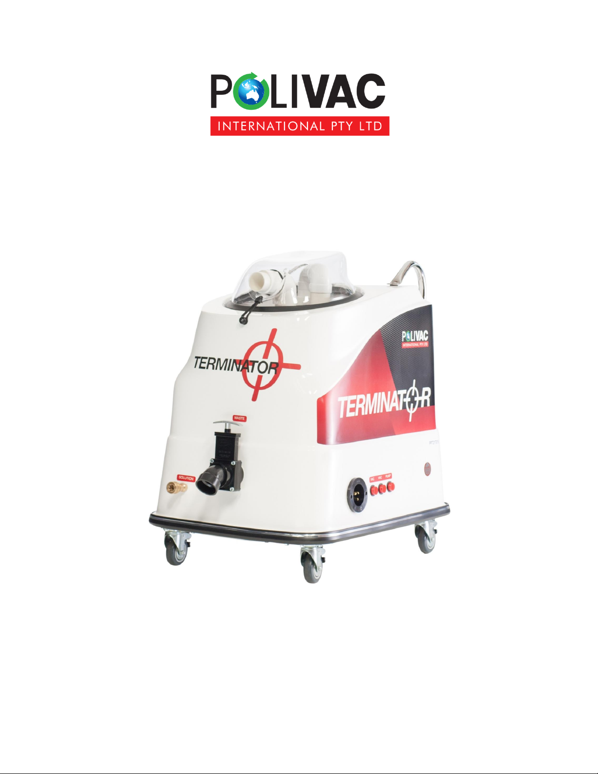
Polivac Terminator User manual

1
Polivac Terminator
Carpet Extractor Machine
Operations Manual & Trouble Shooting Guide

2
Polivac Terminator
Carpet Extractor Machine
Technical Specification
Recovery tank 20 litres
Standard cleaning equipment included
1 x 5 mtr solution hose
1 x 5 mtr vacuum hose
1 x 12 inch 2 jet wand
1 x 15mtr Power cable
Vacuum system 2 x 1100 watt 2 stage tangential motors
Solution Pump 1 x 220 psi sealed electric pump 240v 10A
Fibreglass body with Aluminum sub frame
Switches 3 x Red self-illuminating push button switches.
Water capacity Solution tank 50litres

3
1. 240v power socket inlet.
2. Vacuum # 1 on/off switch
3. Vacuum # 2 on/off switch
4. Solution Pump on/off switch.

1. Solution outlet fitting.
2. Waste water dump valve
Pictured above shows the waste water dump valve in the up position allowing the water to be
Emptied & disposed of. The valve is a slide gate sealed unit that only requires operator
To lift up to dispense water & to push down to close.
Ensure valve is completely closed before operation to obtain maximum suction.

5
Pictured above is the water cut off system used in the Terminator. The Float switch cut off
waste water from entering the vac motors.
This is the working position of the float.
1)Please note once dirt water level reach the float switch trigger, whole machine will stop
working.
2)User should then switch off all 3 X round switches. then empty the dirt water tank using
dump valve.
3) please check filter.Tthere may be larger dirt stuck on it.if so need to remove them for better suction.
particles stuck there.if so please remove them
4)User can start the job again.

7
The above picture shows the exhaust point for the vacuum motors.
If at any stage the operator experiences water coming from this point it indicates
Foam is passing by the filter & this needs to be stopped. Water coming from this point
Can only come thru the vac motors. To prevent foam build up, use an antifoaming
Chemical agent. Do so by pouring a small amount of antifoam solution directly into
Waste tank prior to steam cleaning.

8
Fig 7
1 x 5mtr solution hose
Fig 8
1 x 12" Floor Wand
Fig 9

9
Operational instructions for Terminator
1. Connect power cable to 240v socket inlet (Fig 1 # 1)
2. Connect the male end of solution hose (Fig 8) to the solution outlet on machine (Fig2)
3. Connect the female solution hose end to the male connection of the wand trigger (Fig 9)
4. Take the G-vac hose (Fig7) & connect to the wand end & the inlet on the dome.
5. Fill unit with hot or cold water Note Do not exceed 50 degrees Celsius for hot wa

Terminator
Drawings by: LeanSynergicDesign.com.au
Cabinet Assembly
10
11
12
8
13
7
33
25
29
23
20
28
26 6 5 2 3
4
14
27
32
24
1
17
30
31
9
4
4
16
15
24
34
35
19
21
22
23
18
19
11
15
36
36
14
15
4
27
16
37

Terminator
Drawings by: LeanSynergicDesign.com.au
No Code Description
1 PPT000 Fibreglass Body
2 PM054 Dump Valve
3 PPR029 Dump Valve Spout
4 PM027 Pipe 40 mm
5 PPR080 Female Connector
6 PPR051 Brass BRB
7 PM031 Dome Seal
8 PM035 Dome Complete
9 PPR030 Seal
10 PM064 1.1/2'' Male Socket
11 PPR135 Button & Loop Set
12 PPR098 4 X 16 mm Pak Phillip
13 PM028A Pullman / Terminator handle
14 PM055 Plastic Elbow
15
16 PPT022 Float Switch Bracket
17 PM033 90 Deg Elbow
18 PPR114 Dome Latch
19 AAK854 Rivet
20 PPR177 Screw
21 VLB608 Rubber Washer
22 PPR104 Washer
23 PPR096 Nyloc
24 PPT010 Terminal Label (one set)
25 PPR049 Vent Cover
26 PPR002 Continental Trim
Cabinet Assembly Part List
No Code Description
27 PM037 50 mm Pipe
28 PPR103 Screw
29 PPR128 Washer
30 PVT025 Flat Washer
31 PPR095 M4 Nyloc
32 PM001 Socket
33 PVT029 Pan Phillips
34 AAK838 Rivet
35 PPR035 Float Ball
36 PPR013 Filter Screen
PPR144 Float Switch
37 PM037A Cap for the Filter

Terminator
Drawings by: LeanSynergicDesign.com.au
Frame Assembly
11
3
1
8
5
7
8
9
7
4
6
8
8
1
8
11
8
2
7
13
14
12
10

Terminator
Drawings by: LeanSynergicDesign.com.au
Frame Assembly Parts List
No Code Description
1PPR005 Side Frame 25x25x3x390 mm
2 PPR006 Front Frame 25x25x3x320 mm
3 PPR007 Rear Frame 25x25x3x360 mm
4 PPR009 Wheel Plate
5 PPT003 Castor Wheel
6 PPT002 Bottom Cover
7 PPR090 6 X 20 mm SS
8 AAA354 6 mm Nyloc Nut
9 PVT029 Pan Phillips
10 PPT001 Vacuum Motor Plate
11 PPR091 6 x 20 mm c/ Sunk Bolt
12 AAF141 Nyloc Nut
13 AAG236 Washer 1/4'' x 5/8'' Zinc Bright
14 AAG365 Washer

Terminator
Drawings by: LeanSynergicDesign.com.au
Under Carriage Assembly
1
23
4
5
19
18
8
21
14
15
12
13
16
24
20
7
6
23
11
10
17
17
26
11
9
25
14 15
22

Terminator
Drawings by: LeanSynergicDesign.com.au
Under Carriage Assembly Parts List
N o C o d e Description
1 PPR022 Round Switch
2 PPR048 Inlet Socket
3 PPR098 Pan Phillips
4 PVT025 Stainless Washer
5 PPR095 Nyloc Nut
6 PPR059A Reducer
7 PPR032 Monel Screen
8PM064 Female to Male Adaptor
9PM032 90 Deg Female with Flange
10 PPR039ARed Hose 3/8''
11 PPR042 Hose Clamp 13-20
12 PPR044 Muffler end Cap
13 PPR105 C/ Sunk Phillips
14 PPR040 Silver flex Hose
15 PPR043 Hose Clamp 40-55
16 PPR189B 220 PSI Diaphgragm Pump
17 GAS035 Brass Elbow
18 SLB039 Flat Washer
19 PPR095 Nyloc Nut
20 PPR212 4 X 30 mm Pan Phillips
21 PVT002 Vac Motor
22 COM086 Motor Seal
23 PPR051 Brass BRB
24 PPR138 Round Ferrite
25 PM064 Female to Male Adaptor
26 PPR039 Yellow Hose 3/8''

Polivac International Standard Warranty Terms (v2)
pg. 1
WARRANTY POLICY
1. When a warranty repair is requested, the purchaser must first contact any of Polivac’s authorized Service Centres with proof of
purchase and details of the alleged defect. In most instances, the request for warranty brought to the attention of our Service
Centres or Agents is handled in a prompt routine manner with no question as to its validity. However, some requests for warranty
are not justified. In these cases, product owners will be made aware that the premature failure of their product was the result of a
cause not covered by Warranty.
2. The Polivac warranty covers only DEFECTIVE MATERIAL and/or DEFECTIVE WORKMANSHIP. It does not cover labour.
3. Polivac products are warranted for twelve (12) months from date of purchase by the original purchaser against faulty
workmanship or material. The warranty covers only the replacement, repair or adjustment of any part which in the opinion of
Polivac fails because of a fault in materials or workmanship:
a) drive motors and gearbox assemblies on electrical products carry a two (2) years warranty
b) bodies of carpet extraction products and vacuum cleaners carry a three (3) years conditional warranty.
c) battery warranty of twelve (12) months is as provided by the manufacturer. Terms available on request.
4. Where the product has been rented out by a Hire or similar company, the warranty period is reduced to three (3) months.
5. This warranty does not cover service calls, travelling time or consumable parts - e.g. drive belts, chains, flexible skirts or hoses,
dust bags, mains leads, brushes, buffers, buffer strips, sanding discs, light bulbs, nozzles, filters, pressure pumps, piston seals,
diaphragms, squeegees and like items.
6. In the case of proprietary components used by the manufacturer in the product, such as engines, electrical motors, chargers and
the like, Polivac will pass on any warranty provided by the manufacture of such items.
7. Accidental damage, abuse, misuse or neglect of the product is not covered by warranty.
8. Fair wear and tear and where the product has been used other than for the purpose for which it was designed is not covered by
warranty.
9. Use of non-approved chemicals and detergents in the product will void the warranty.
10. Products that have been modified are not covered by warranty.
11. Products that have not been serviced at their recommended intervals by an authorised Polivac Service Centre or Agent are not
covered by warranty
12. Damage to, or failure of, the product which has resulted from low or high voltage, the use of an incorrectly sized extension lead,
or a coiled electrical extension lead is not covered by warranty.
13. Repairs carried out on the product by any person other than an authorized Polivac repairer will void the warranty.
14. All freight charges to and from the manufacturer, agent or service centre will be the responsibility of the distributor.
15. A charge for traveling time and labour will be applicable for on-site warranty service.
16. Polivac reserves the right to replace defective parts of the product with parts or components of similar quality, grade and
composition where an identical part or component is not available. Goods presented for repair may be replaced by refurbished
goods of the same type rather than being repaired.
POLIVAC WARRANTY IS SUBJECT TO THE LAWS AND REGULATIONS OF THE INDIVIDUAL STATES AND COMMONWEALTH
TERRITORIES OF AUSTRALIA. THIS WARRANTY IS NOT TRANSFERRABLE.
Table of contents
Other Polivac Floor Machine manuals

Polivac
Polivac GAZ20 User manual

Polivac
Polivac Predator MK II User manual

Polivac
Polivac GASS38KOH User manual

Polivac
Polivac Predator MK III User manual

Polivac
Polivac GAZ24 User manual

Polivac
Polivac ST2100 User manual

Polivac
Polivac Predator MK I User manual

Polivac
Polivac GAZ20 User manual

Polivac
Polivac Predator MK II User manual

Polivac
Polivac Stealth Series User manual