Polyvance 6180 User manual

Page 1
POLYVANCE
PART NO. 6180
MINI-FUZER HOT AIR PLASTIC WELDING STATION
USER MANUAL
Thank you for purchasing the Polyvance 6180 Mini-Fuzer Hot Air Plastic Welding
Station. This product has both a hot air welder torch and an airless welder iron.
The hot air torch has adjustable airow and temperature, and the airless welder
iron has adjustable temperature. This product is designed for welding plastic
parts.
Please read this manual before operating the Polyvance 6180 Mini-Fuzer. Keep
this manual readily accessible for reference
Polyvance
1128 Kirk Rd
Rainsville, AL 35986 USA
Phone: +1-256-638-4103
www.polyvance.com
Revision Date: July 2023 - PB01
M1 M2 M3

Page 2
TABLE OF CONTENTS
1.0 Warnings, Cautions, and Notes 7.0 Setting Memory Buttons
2.0 Tool Schematic 8.0 Welder Function Setup
3.0 Specications 9.0 Plastic Welding
4.0 Initial Setup 10.0 Troubleshooting
5.0 Control Panel 11.0 Limited Warranty
6.0 Welder Operation
1.0 WARNINGS, CAUTIONS, AND NOTES
This manual provides critical safety instructions on the proper opera-
tion, maintenance, and service of this tool. Failure to read, understand,
and follow the instructions given in this manual may result in personal
injury. The owner of this tool is solely responsible for its safe use. Poly-
vance recommends that all users read and understand the information
in this manual prior to using the equipment. Polyvance will not be held
liable for injury or property damage from negligence, improper training,
machine modication, or misuse.
WARNING
This product contains materials that are known to the State of California to cause cancer,
birth defects, or other reproductive harm. (Prop 65 warning)
GENERAL HAZARDS
Portable electric heating devices, such as this plastic welder, possess certain inherent
hazards due to hot surfaces and hot air emissions.
Function of the hot air welder requires that the air inlet on the front of the welder to not be
blocked or clogged. Replace lter element if it becomes clogged.
Fumes may be emitted during operation. Use in a well-ventilated area. Use a properly tted
organic vapors respirator if needed to prevent inhalation of fumes.
Hot air torch and airless welder iron should be returned to their holsters when the tool is not
in use. Do not lay hot tools on any other surface when not in use.
This product is not intended for use in paint stripping operations.
FIRE HAZARDS
The temperatures necessary for their normal use are high enough to cause re if the hot
tool is left in contact with or near combustible materials.
Never use this tool near ammable liquids or vapors.
BURN HAZARDS
Do not touch hot metal parts! During normal operation, the metal parts of
the hot air torch, the airless welder iron, and the airless welder holster are
hot enough to cause severe burns even at the lowest possible temperature
settings.
ELECTRICAL SHOCK HAZARDS
Tool is designed for indoor use only. Do not expose to rain or snow.
Do not use in or near water. Do not immerse in water. Do not use the tool
in the rain. Do not use if the tool is wet.
Do not use if cord, switch, or heating element are damaged.

Page 3
Unplug tool before servicing. Never attempt to service the tool while it is
plugged into a power source.
Warning: Electric shock hazard, where the appliance is used without the
ground (earth) connection.
警告:機器を接地しないで使用すると感電する危険がある。
2.0 TOOL SCHEMATIC
3.0 SPECIFICATIONS
Power Requirements
Rated Voltage Range (see plac-
ard on back of tool)
North America: 110 - 127 V / 60 Hz (~3.0 amp)
Japan: 100-110 V / 60 Hz (~3.7 amp)
Rest of World: 220 - 240 V / 50 Hz (~1.5 amp)
Rated Power 370 W
Certication Duty Cycle 15 minutes maximum continuous use of hot air weld-
er outside of holster / 5 minutes OFF. Always return
hot air welder to holster when not in use to engage
auto-cooldown mode.
Physical Specications
Cabinet Size 253 mm x 186 mm x 124 mm (10 in x 7.3 in x 4.9 in)
Weight 5.13 kg (11.3 lb)
Ambient Working Conditions 1-40°C (32 - 104°F)
M1 M2 M3
Hot Air
Welder
Torch
Hot
Air
We
lder
Holster
Airless
Welder
Airless
Welder
Holster
LCD
Screen
Main Power
Switch (on
back panel)
Hot Air
Flow
Control
Knob
Control
Panel
Air pump inlet
(replace filters
when needed)
Hot Air
Reduction
Nozzle

Page 4
Display Type LCD
Hot Air Welder Specications
Air Pump Type Diaphragm pump
Airow 0 - 28 liters per minute (0 - 1 CFM)
Temperature Range 100 - 480°C (212 - 896°F)
Temperature Stability ±1°C
Torch Hose Length 1.8 – 2.1 m (71 - 82 in)
Airless Welder Specications
Temperature Range 100 - 480°C (212 - 896°F)
Tip to ground voltage < 2 mV
Tip to ground impedance < 2 Ω
Welder Cord Length 1.8 - 2.1 m (71 - 82 in)
4.0 INITIAL SETUP
Remove all components from the box.
Remove the two screws marked in red on the
bottom of the welding machine as shown in Fig.
1. Cut the plastic zip tie and remove it. These
components secure the diaphragm pump during
shipping and may be discarded upon installation.
Using the two screws on the left side of the
machine, install the hot air torch holster as shown
in Fig. 2.
Using the two screws on the right side of the
machine, install the airless welder holster as
shown in Fig. 3.
Attach the airless welder to the welder on the front
panel by lining up the notch at the top of the plug
with the socket, then turning the nut to secure the plug in place.
Install the reduction nozzle to the end of the hot air torch.
Plug the power cord into the back of the welder, then plug it into a power source that
matches the requirements of the placard on the back of the welder.
Figure 1
Fig. 3 - Install airless welder holster
Fig. 2 - Install hot air welder holster

Page 5
5.0 CONTROL PANEL
6.0 WELDER OPERATION
Main Power On - For safety, prior to turning on the main power, make sure the hot air weld-
er and the airless welder switches on the front of the welder are turned o. Turn on the main
power switch on the back of the welder. You will hear a beep and the LCD screen will turn
on, showing two sets of three dashes.
Main Power O - Do not turn the main power o until the hot air welder cooldown cycle is
complete and the air pump turns o. Damage to the hot air welder may occur if the main
power is switched o before the cooldown cycle is complete.
6.1 Airless Welder Operation
Turn on the airless welder switch on the front of the welder. The LCD screen will briey
show the temperature setpoint (factory setting 400°C), then you will see the actual tempera-
ture of the heating element as it increases toward the setpoint. Allow about ve minutes for
the welder tip to reach full operating temperature.
The airless welder will automatically turn o if it is not used within the number of minutes
shown above the “SLEEP” indicator on the LCD screen.
When the airless welder turns itself o, the display will ash between “SLP” (for “sleep”
mode) and the low temperature point (100°C or 212°F).
If the airless welder is in sleep mode, when you pick it up out of its holster, it will start to
heat up again. Note that additional time is required to heat up the metal of the tip; the actual
metal temperature of the tip lags behind the indicated temperature on the LCD screen.
6.2 Hot Air Welder Operation
Make sure the hot air welder torch is in its holster.
Turn on the hot air welder switch on the front of the welder. The LCD screen will briey
show the temperature setpoint (factory setting 400°C), then you will see three dashes and
the words “HOT AIR” underneath indicating that it is ready.
Pick up the hot air welder torch from the holster. You will hear the air pump operate and see
the temperature rise toward the setpoint as it heats the air. When the temperature reaches
the setpoint, the welder is ready to use.
-+
Flow
Push - Cool / Heat
-+
Hot Air
Airless
-+
M1 M2 M3
Airless
Hot Air Air Inlet Do Not Block
Hot air welder
airflow control knob
Memory buttons
Airless welder
temperature
adjustment buttons
Hot air welder
temperature
adjustment buttons
Hot air welder
power switch
Airless welder
power switch

Page 6
When you return the torch to the holster, the welder will start its automatic cooldown pro-
cess. The air pump remains on to cool the heating element. You will see the temperature
reduce. Once it returns to 100°C (212°F), the air pump will automatically turn o. The LCD
screen will return to showing three dashes and the words “HOT AIR”, indicating that the
torch is ready to use once you pick it up from the holster.
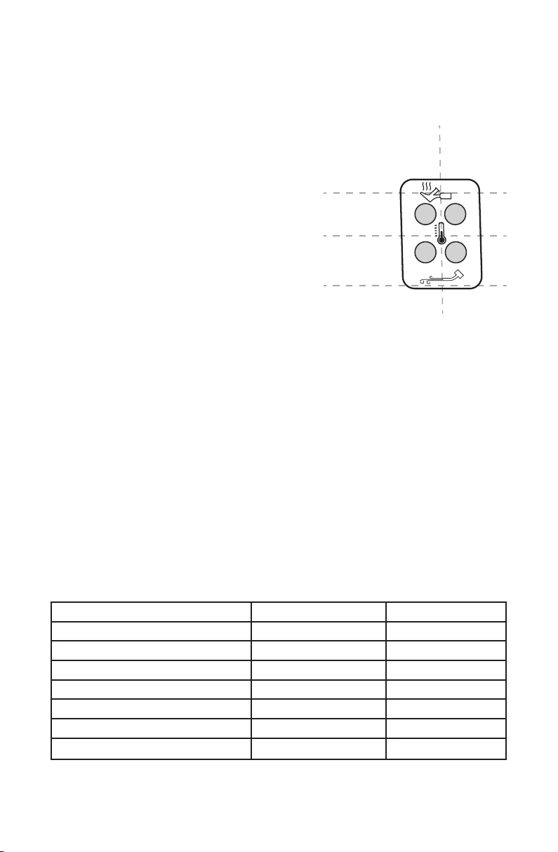
6.2.1 Adjusting Welder Temperature - To adjust the
welder temperature, push the appropriate buttons on
the control panel as shown in the image to the right.
6.2.2 Adjusting Hot Air Welder Airow - Rotate the
airow control knob clockwise to increase ow and
counterclockwise to reduce ow. The graphic on the
LCD screen gives a visual indication of the relative
ow rate. The ow rate may be adjusted to suit the
thickness of plastic being welded. Typically, thicker
plastics will need higher ow and thinner plastics will
need lower ow.
6.2.3 Toggling Hot Air Welder Power - Pushing the
airow control knob will toggle power to the hot air
torch. Push the knob once and you will see the words “HOT AIR” on the LCD screen turn
o and you will see the temperature readout start to come down. The air pump will remain
on until the heating element is cooled down. Push the knob again and the words “HOT AIR”
on the LCD screen will turn on and the temperature will start to rise toward the setpoint.
Returning the torch to the holster will start the automatic cooldown process, so toggling the
power with the knob is not needed in most situations.
7.0 SETTING MEMORY BUTTONS
You may save your preferred welder settings with one of the three memory buttons, labeled
M1, M2, and M3. To save preferred welder settings, adjust the welder’s parameters (airow,
hot air welder temperature, airless welder temperature, and C°/F°) to the settings you want
to save. Press and hold the memory button to which you would like to save these settings
for two seconds, until you hear a beep. These settings are now saved to that button.
Airow setting depends on the thickness of the plastic you are welding. Reduce airow
when welding thin plastics. Increase airow when welding thick plastics.
Temperature setting depends on the type of plastic you are welding. Use the settings in the
below table as a guide for welding various common plastics. Adjust up or down as neces-
sary to suit your need.
Plastic Type Hot Air Temp. Setting Airless Temp. Setting
ABS - acrylonitrile butadiene styrene 325°C / 620 °F 325°C / 620 °F
HDPE – high density polyethylene 400°C / 750 °F 400°C / 750 °F
LDPE – low density polyethylene 375°C / 700 °F 375°C / 700 °F
PA – polyamide (nylon) 450°C / 840 °F 450°C / 840 °F
PC - polycarbonate 350°C / 660 °F 350°C / 660 °F
PP – polypropylene 400°C / 750 °F 400°C / 750 °F
PUR - polyurethane (do not use hot air on PUR) 290°C / 550°F
-+
Hot Air
Airless
-+
A
irless welder
temperature
adjustment buttons
Hot air welder
temperature
adjustment buttons
Press left
button to
reduce
temperature
Press right
button to
increase
temperature

Page 7
8.0 WELDER FUNCTION SETUP
Several welder functions can be adjusted by pressing and holding two buttons simultane-
ously for about four seconds until a beep is heard.
8.1 Celsius / Fahrenheit Temperature Display
The default temperature display from the
factory is in Celsius (°C). To change to Fahr-
enheit (°F) display, press and hold the two
buttons until a beep is heard. You will see
the °C/°F indicators ash. While the indica-
tors are ashing, press the bottom button to
change to °F. Press the top button to change
to °C. After about ve seconds, the indicators
will stop ashing and the preferred tempera-
ture readout will be selected.
8.2 Hot Air Welder Auto/Manual Mode
Selection
The factory setting for the hot air welder is
“AUTO” mode. This means that the welder
will automatically cool down when the torch
is placed into the holster. The torch will
also heat up automatically when the torch
is removed from the holster. Polyvance
recommends that you leave it in Auto mode
because it is the safest and most economi-
cal setting. Also, the heat-up time for the hot
air torch is very short, so it will not reduce
your productivity by leaving it in Auto mode.
If for some reason you want to change the
hot air welder to “MANUAL” mode, press
and hold the two hot air buttons simulta-
neously until a beep is heard and the Auto/Manual indicators ash. Press the left button to
switch to Manual mode and the right button to switch to Auto mode. After about ve sec-
onds, the indicators will stop ashing and the preferred hot air welder mode will be selected.
8.3 Airless Welder Sleep Time Setting
The factory setting for the airless welder sleep
time is 10 minutes. This means that, if the
airless welder remains unused in the holster for
10 minutes, it will turn itself o and go into sleep
mode. When you pick up the airless welder, the
airless welder will begin to heat back up to the
setpoint.
Unlike the hot air welder, it may take several
minutes for the tip of the airless welder to reach
the setpoint. So increasing the sleep time of the
airless welder may improve your productivity.
To change the airless welder sleep time, press
and hold the two top buttons simultaneously
-+
Hot Air
Airless
-+Push and hold
these two buttons
simultaneously to
change tempera-
ture readout
between °C and °F
°C
°F
-+
Hot Air
Airless
-+
Push and hold
these two buttons
simultaneously to
change between
A
uto and Manual
mode on hot air
welder
Left button =
Manual mode
Right button =
Auto mode
-+
Hot Air
Airless
-+
Push and hold
these two buttons
simultaneously to
adjust airless
welder sleep time
Left button =
Reduce time
Right button =
Increase time

Page 8
until a beep is heard. You will see the “SLEEP” indicator begin to ash. While the Sleep
indicator is ashing, press the right button to increase the sleep time and the left button to
reduce the sleep time. Sleep time may be varied in one minute increments from 0 to 99
minutes. After about ve seconds, the indicator will stop ashing and the selected sleep
time will be stored.
9.0 PLASTIC WELDING
The following instructions will explain how to weld plastic with both the hot air welder and
the airless welder. The airless welder’s versatility allows you to weld thermoplastics, repair
thermoset polyurethane, and melt in stainless steel wire mesh to reinforce your repair.
9.1 Hot Air Welder
The diagram shown here illustrates the orientation of the hot air welder and welding rod,
along with some parameters to set and keep in mind during the process.
Welding with hot air involves the coordination of both hands; one controlling the torch and
the other feeding the rod. During the process, melt the bottom surface of the rod and the
top of the substrate. Don’t “puddle” the rod like in metal welding. This makes for a stronger
repair because it leaves the basic structure of the rod intact. During the welding process,
melt both the base material and the rod at the same time and fuse the melted surfaces
together with a slight downward pressure on the rod as the pass is made.
• Set the temperature to the setting that matches the type of plastic being welded. Refer
to the temperature chart on Page 6.
• The airow should be set depending on the plastic’s thickness; less for thinner plas-
tics, more for thicker plastics.
• An angle of 45° between the welder tip and the substrate is optimum. Aim the stream
of hot air a little in front of the rod. The rod should be about a 90° angle to the base
material.
• The distance of the welder’s tip to the work is important because the temperature of
the gas stream drops quickly the farther away the tip is. Keep the tip about 5 mm (1/4”)
to the work.
• Apply a light downward pressure on the rod to fuse the rod and base material. Keep a
steady downward pressure on the rod and keep the rod moving slowly.
Angle = 45°
Pressure
0.2 - 0.5 kg
(0.5 - 1 lb)
Speed
10-15 cm/min
(4 - 6 in/min)
Temperature
325°- 450°C
(620° - 840°F)
Air Flow
8-15 L/min

Page 9
• The speed of the weld should be about 10-15 cm (4 to 6 inches) per minute. Move
steadily while making sure the base material and the bottom surface of the rod are
both melted before they come together.
See instructional videos on www.polyvance.com or search for Polyvance on YouTube.
9.2 Airless Welder - Welding Thermoplastics
“Thermoplastics” are plastics that melt when heated and resolidify when cooled. Look for
an identication symbol molded into the part, or do test welds with various welding rods to
see which one sticks best.
Line up the outer surface of the crack using clamps or aluminum tape.
Create a v-groove along the crack with the edge of the hot welder
tip, or use a grinding tool. Pre-melt the v-groove.
With the airless welder temperature set at the proper
level to match the plastic being welded (see table
on Page 6), melt the ller rod into the v-groove for a
length of about 25 mm (1 in.), then remove the rod
from the tip and go back over the welded area to
mix the base material and rod together.
DO NOT press down on the welding iron with ex-
cessive pressure. The heating element is not designed to
resist heavy pressure. Use a light touch, be patient, and
let the heat do the work. (Polyvance’s line of Nitro-Fuzer
professional-quality welders have a more robust airless
welder handle design for greater durability.)
Allow weld to cool completely. Remove
clamps or aluminum tape. Repeat the pro-
cess on the opposite side.
See instructional videos on www.polyvance.
com or search Polyvance on YouTube.
9.3 Airless Welder - Welding Thermoset Polyurethane
“Thermosets” are plastics that do not melt. They are formed by a chemical reaction be-
tween two components to make a solid plastic material. The only thermoset plastic that can
be repaired with the airless plastic welder is polyurethane (PUR) a common material for
bumper covers in the 1970’s through the 2000’s, and is still used today.
Line up the outer surface of the crack
using clamps or aluminum tape.
Grind a v-groove about halfway
through the plastic with a rotary tool.
You cannot melt the v-groove in
because PUR is not meltable.
Set the temperature of the airless
plastic welder to 290°C (550°F) and
feed the R01 urethane welding rod
through the welder tip as shown. The
rod should come out the bottom fully
melted, but not smoking and bubbling.
Adjust the temperature setting as needed.

Page 10
Holding the welder’s tip slightly o
the surface of the plastic, melt the rod
into the v-groove. Deposit no more
than two inches (5 cm) of welding rod
at a time. Remove the rod from the
welder tip and use the hot welder tip to
smooth out the weld. Do not attempt
to melt the base material. The welding
rod acts like a hot melt glue or a
brazing rod when repairing thermoset
polyurethanes. Allow the repair on the
backside to cool completely, remove
the tape, and repeat the process on
the opposite side.
See instructional videos on www.polyvance.com or search Polyvance on YouTube.
9.4 Airless Welder - Melting in Reinforcing Wire Mesh
Thermoplastic (i.e. meltable) plastics may be reinforced by melting stainless steel wire
mesh into the plastic. The mesh locks into the undamaged substrate in the area and trans-
fers stresses across the crack into the substrate to increase the strength of the repair.
To reinforce a repair, cut a piece of mesh about 15 mm (5/8”) wide and about the length of
the crack using a pair of scissors or tin snips. Lay the mesh on the backside of the plastic
and, using the hot airless welder
tip, start at one end of the mesh
and press the mesh into the
surface.
DO NOT press down on the
welding iron with excessive pres-
sure. The heating element is not
designed to resist heavy pressure.
Use a light touch, be patient, and
let the heat do the work. Once the
mesh is embedded into the plastic,
move the tip to the next section. Use a screwdriver or similar tool to apply pressure to keep
the mesh embedded in the plastic until the plastic resolidies.
10.0 TROUBLESHOOTING
10.1 Hot Air Welder Not Cooling Down
The hot air welder holster has two small magnets that trigger the sensor in the handle. If the
hot air welder is not cooling down automatically when the handle is placed in the holster,
rst check that the rubber handle grip is slid all the way toward the nozzle. Then rotate the
torch in the holster slightly until the sensor is triggered by the magnets in the holster.
If the hot air welder continues to malfunction or displays “S-E” (sensor error), contact
Polyvance or your authorized distributor for instructions.
Hold welder
slightly above
surface. Do not
attempt to melt
the base material.
Do not apply heavy
pressure. Let the
heat do the work.

Page 11
10.2 Airless Welder Barrel is Bent
The 6180 Mini-Fuzer is not designed for heavy-duty, professional, or industrial use. The air-
less plastic welder, in particular, cannot withstand heavy downward pressure on the handle.
Use only a light downward pressure on the airless heating element. Bending of the airless
plastic welder’s barrel is excluded from the one-year warranty on this product (see below,
Section 11.0)
If you need a professional-quality, heavy-duty airless heating element, purchase one of
Polyvance’s plastic welders that feature a 6012 ceramic heating element, like the Nitro-
Fuzer line of nitrogen plastic welders.
11.0 LIMITED WARRANTY
The 6180 Mini-Fuzer is warranted against defects in materials and workmanship for a
period of one year from the date of purchase. Any part found to be defective during the
warranty period will be repaired or replaced free of charge when returned prepaid with
a copy of the original invoice showing the date of purchase. An RGA (Returned Goods
Authorization) number must be obtained from Polyvance (or its authorized distributor in
your country) prior to any repair or return.
Damage to the welder due to mishandling, impact, or other misuse is strictly excluded from
this warranty.
Bending of the airless welder’s barrel due to excessive downward pressure being applied to
the handle is strictly excluded from this warranty.
DO NOT PUSH DOWN
WITH EXCESSIVE
PRESSURE!
BENDING OF ELEMENT
HERE NOT COVERED
BY WARRANTY

Page 12
Polyvance
1128 Kirk Rd
Rainsville, AL 35986 USA
Phone: +1-256-638-4103
www.polyvance.com
Scan the QR code to download User Manuals in other languages.
Escanea el código QR para descargar los manuales de usuario en otros idiomas.
Scannez le code QR pour télécharger les manuels d’utilisation dans d’autres langues.
Escaneie o código QR para baixar os Manuais do Usuário em outros idiomas.
Scansiona il codice QR per scaricare i Manuali Utente in altre lingue.
Scannen Sie den QR-Code, um Bedienungsanleitungen in anderen Sprachen herunterzuladen.
他の言語でのユーザーマニュアルをダウンロードするには、QRコードをスキャンしてください
请扫描QR码以下载其他语言的用户手册。
Quét mã QR để tải xuống Hướng dẫn sử dụng trong các ngôn ngữ khác nhau.
Table of contents
Other Polyvance Welding System manuals
Popular Welding System manuals by other brands

Saf-Fro
Saf-Fro PRESTO 300MV Instructions for use safety and maintenance

Huayuan Electric
Huayuan Electric ZD7-1600IGBT Manual instruction

Scheppach
Scheppach WIG2000-Multi Translation of the original operating manual

Hypertherm
Hypertherm Powermax1100 Operator's manual

ANDELI
ANDELI TIG-250GPLC user manual

Miller Electric
Miller Electric Millermatic Vintage M-25 Gun owner's manual