Populas INFINITY User manual
Other Populas Indoor Furnishing manuals

Populas
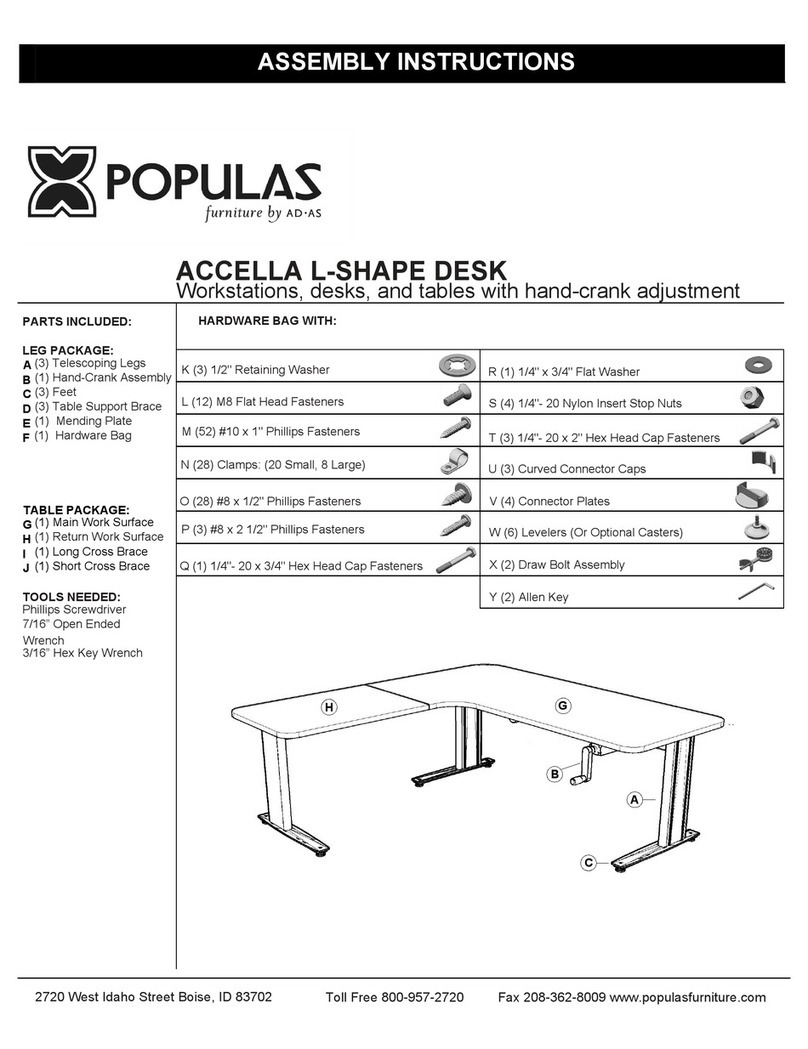
Populas ACCELLA User manual

Populas
Populas VOX L-SHAPE DESK User manual

Populas
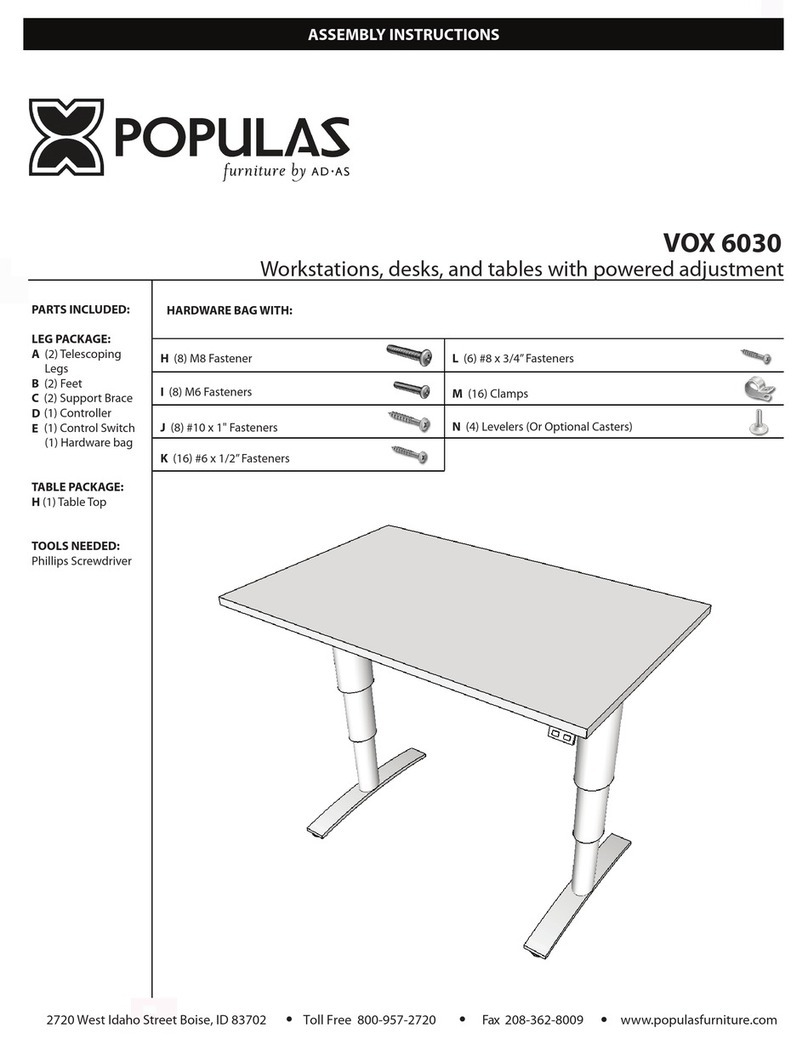
Populas VOX 6030 User manual

Populas
Populas Infinity 4836GT User manual

Populas
Populas ACCELLA User manual

Populas
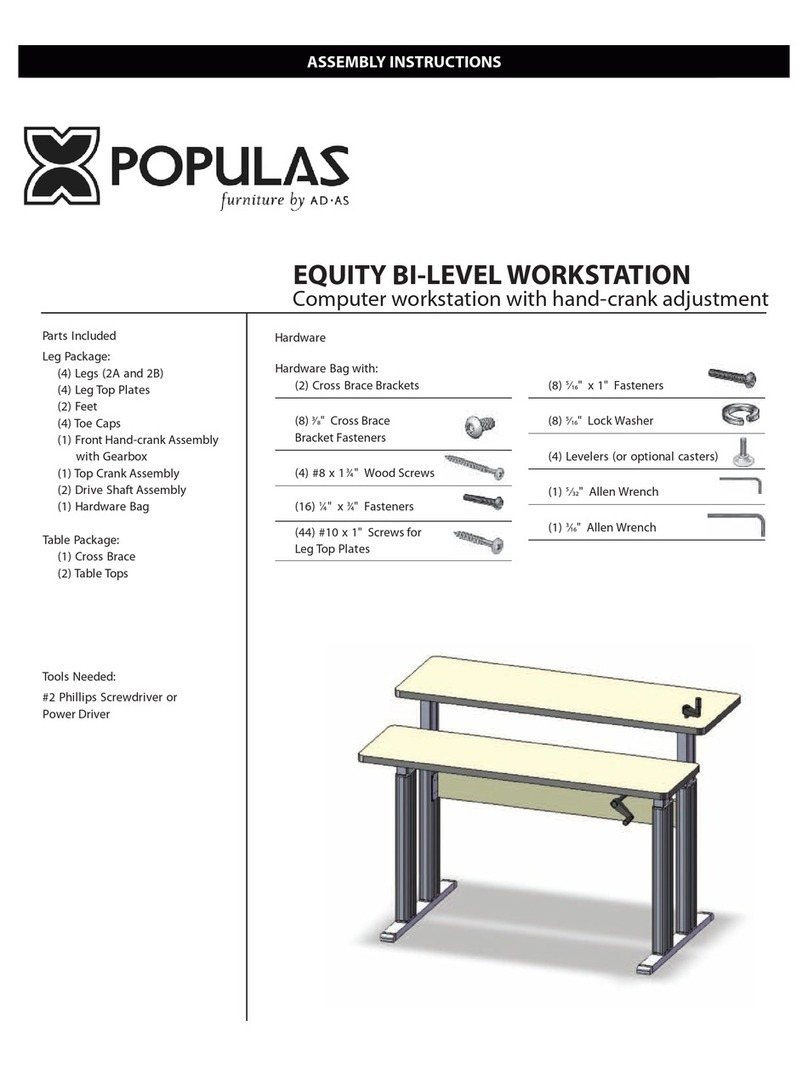
Populas EQUITY BI-LEVEL WORKSTATION User manual

Populas
Populas Equity Workstation EQ 361416 KBL User manual
Popular Indoor Furnishing manuals by other brands

Regency
Regency LWMS3015 Assembly instructions

Furniture of America
Furniture of America CM7751C Assembly instructions

Safavieh Furniture
Safavieh Furniture Estella CNS5731 manual

PLACES OF STYLE
PLACES OF STYLE Ovalfuss Assembly instruction

Trasman
Trasman 1138 Bo1 Assembly manual

Costway
Costway JV10856 manual


