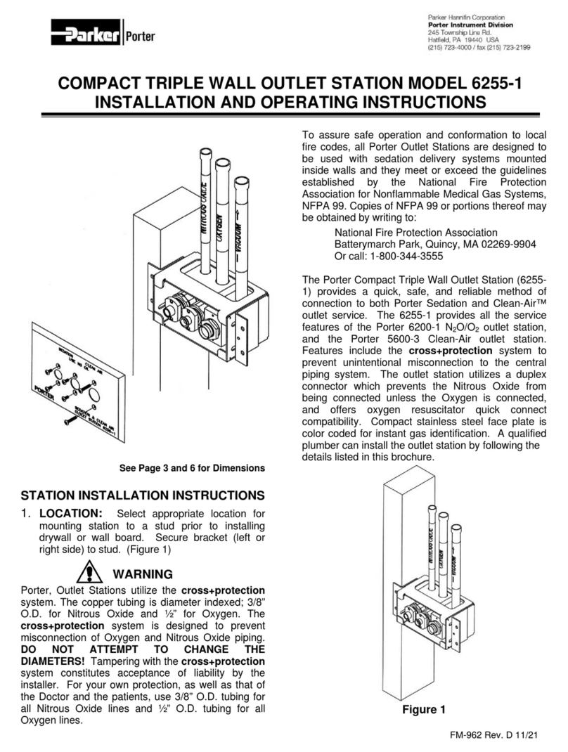
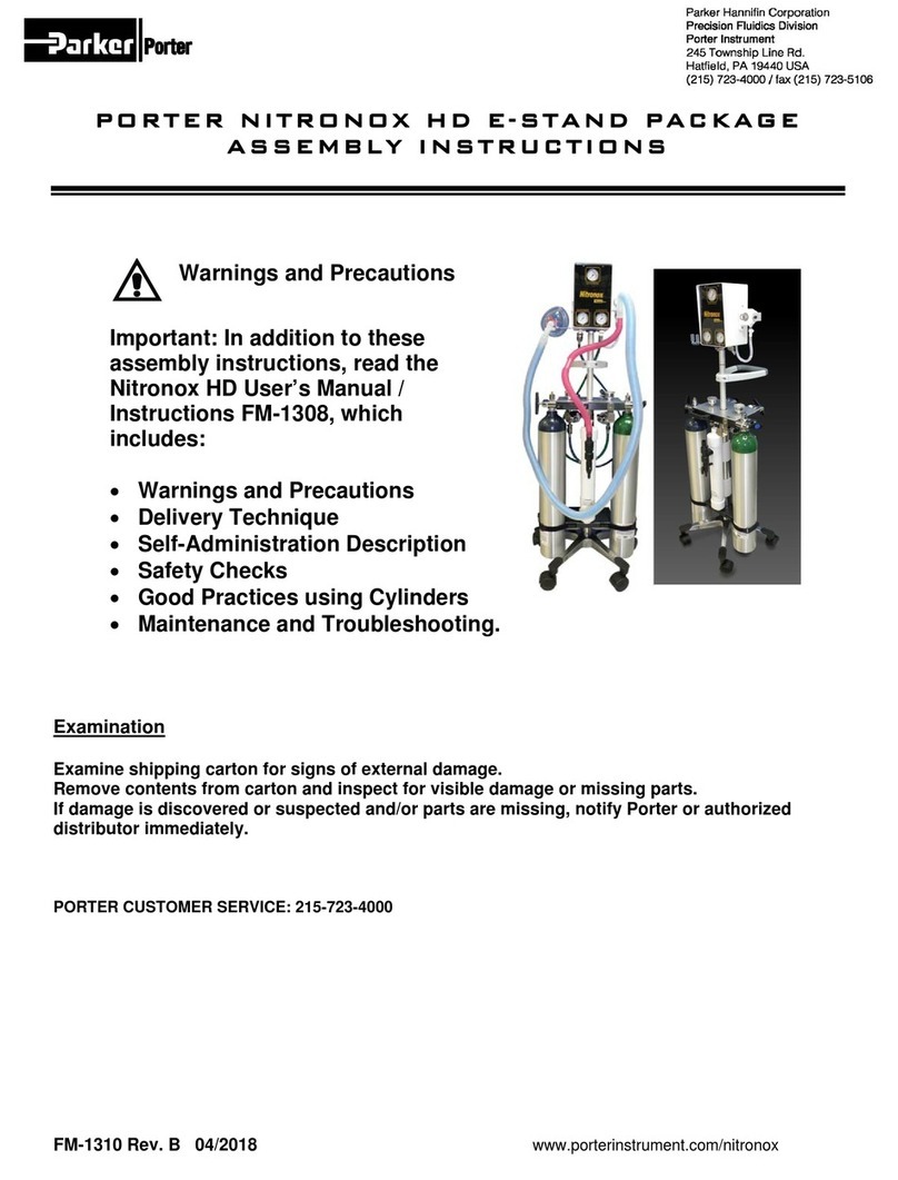
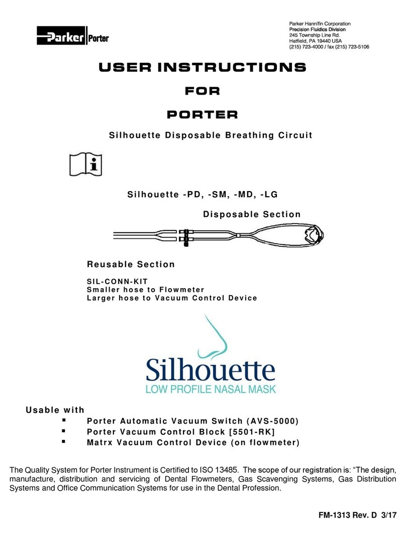
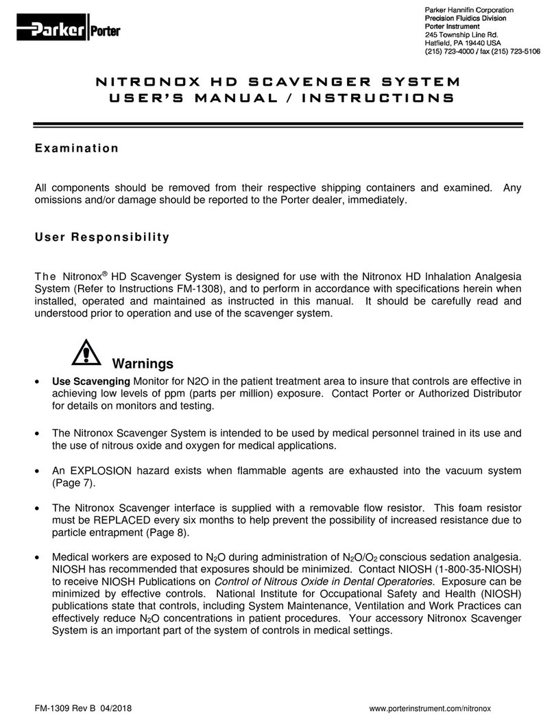
Porter Matrx MDM User manual

Parker Hannifin Corporation
Porter Instrument Division
245 Township Line Road
Hatfield, PA 19440
Office 215 723 4000
Fax 215 723 5106
MDM Monitored Dial Mixer
Nitrous Oxide –Oxygen Sedation Flow Meter
Installation Manual
This product complies with the Medical Device Directive (93 / 42 / EEC).
A “Declaration of Conformity” in accordance with the directive has been made and is
on file.
European Communities should contact the Authorized Representative listed below
regarding any Medical Device Directive (MDD) inquiries.
Contact Name:
Parker Hannifin Ltd Instrumentation Products Division
Mailing Address:
Riverside Road, Pottington Business Park
Barnstaple, EX 31 1NP, England
Phone:
+44 (0) 1271-313131 Fax: +44 (0) 1271-373636
The Quality System for Porter Instrument is certified to ISO 13485. The scope of our registration
is:
“The design, manufacture, distribution and servicing of Nitrous Oxide – Oxygen Sedation
Flowmeters, Gas Scavenging Systems, Gas Distribution Systems and Office Communication
Systems for use by a physician, dentist or licensed healthcare Profession.”
Check our website: www.porterinstrument.com for additional information.
To register your product: www.porterinstrument.com/resources-dental choose Warranty tab.
To download a User’s Manual: www.porterinstrument.com/resources-dental choose Manuals tab
10049600-CE-English Rev. N 4/2013

1
IMPORTANT:
READ MANUAL COMPLETELY BEFORE OPERATING THIS DEVICE
Basic delivery technique is described. Also, this manual contains instructions on periodically required checks
to be performed by the user. These checks are necessary to insure the proper performance of this device
and its safety features. Retain this manual for future reference.
WARNINGS AND PRECAUTIONS
These warnings and precautions are to help you
to understand how to safely operate the MXR
Flowmeter. A WARNING alerts you to a possible
hazard to people. A CAUTION alerts you to the
possibility of equipment damage.
WARNING: Do not use this device for the
administration of general anesthesia or as a part
of, or in conjunction with, a general anesthesia
administration system.
WARNING: Workers are exposed to N2O during
administration of N2O/O2 conscious sedation
analgesia. NIOSH has recommended that
exposures should be minimized. Contact NIOSH
(1-800-35-NIOSH) to receive NIOSH Publications
on Control of Nitrous Oxide in Dental Operatories.
Exposure can be minimized by effective controls.
National Institute for Occupational Safety and
Health (NIOSH) publications state that controls,
including System Maintenance, Ventilation and
Work Practices can effectively reduce N2O
concentrations in patient procedures. Your
flowmeter accessory Porter scavenger system is
an important part of the system of controls.
WARNING: Porter Instrument equipment utilizes
the cross+protection system. The flexible hose
and connectors that connect to the flowmeter are
diameter indexed; 3/8” O.D. for Nitrous Oxide and
½” for Oxygen. The cross+protection system is
designed to prevent misconnection of Oxygen
and Nitrous Oxide piping. DO NOT ATTEMPT
TO CHANGE THE DIAMETERS OR
CONNECTORS OF THE FLOWMETER!
Tampering with the cross+protection system
constitutes acceptance of liability by the installer.
For your own protection, as well as that of the
Doctor and the patients, use 3/8” O.D. tubing for
all Nitrous Oxide lines and ½” O.D. tubing for all
Oxygen lines.
To assure safe operation and conformation to
local fire codes, all Porter Instrument flowmeter
systems are designed to be used with sedation
delivery systems mounted inside walls and they
meet or exceed the guidelines established by the
National Fire Protection Association for
Nonflammable Medical Gas Systems, NFPA 99.
Copies of NFPA 99 or portions thereof may be
obtained by writing to: National Fire Protection
Association, Batterymarch Park, Quincy, MA
02269-9904; or call 1-800-344-3555
WARNING: New or modified installations -
properly connected gas pipelines are
absolutely essential to patient safety. The
authorized distributor or contractor should provide
written documentation that all gas pipelines are
connected properly and that the system has been
pressure tested prior to use. While this is a good
business practice, it is important that the user
verify by their own test, independent of the
authorized distributor or contractor, that all gas
pipelines are connected correctly prior to using
the system. The ultimate responsibility of
assuring that lines are not crossed rests with
the user.
WARNING: During any power outage, remember
to turn OFF the flowmeter and manually turn OFF
the tank valves. With centralized, electrically
powered gas systems, if gas was flowing when
the power went out and the flowmeter is left ON,
gas will be flowing when the power is restored.
CAUTION: This device is for use by or on the
order of a physician, dentist or licensed
healthcare professional.
CAUTION: Always use clean, dry medical grade
gases. Introduction of moisture or other
contaminants into this device may result in
defective operation.
CAUTION: Do not attempt to repair, alter or
calibrate this device. Unauthorized repair,
alteration or misuse of this device is likely to
adversely affect the performance and will void the
warranty.
CAUTION: Never oil or grease any part of this
system (minimize fire or explosion potential).
DESCRIPTION AND MECHANICAL ASSEMBLY
This manual covers the operation of the MDM Nitrous Oxide/Oxygen mixer. The MDM is a mechanical
mixer for regulating the flow of Nitrous Oxide and Oxygen from a gas supply to a conscious patient for the
purpose of conscious sedation analgesia. Each MDM model includes the MDM Flowmeter Head with one
of the following:
Conventional Rubber Goods: 4” Breathing Tube, Large Nasal Inhaler and 3 Liter Breathing Bag
Assembly Procedure:
1. Position breathing bag as shown and slide opening in breathing bag over outside diameter of bag
mount. (Figure 1)
2. Slide one end of breathing tube over outside diameter of breathing tube connector.
3. Slide connector “Y” fitting of large nasal inhaler into free end of breathing tube.
Or
N2O - O2Scavenger: Large Scavenger and 3 Liter Breathing Bag (Figure 2)
Assembly Procedure:
1. Position breathing bag as shown and slide opening in breathing bag over outside diameter of bag
mount. (Figure 1)
2. Slide the 22mm hose cuff of the scavenger over the breathing tube connector. (Figure 2)
3. Refer to scavenging nasal inhaler instructions for methods of connecting vacuum shut-off valve
MDM AS SUPPLIED WITH CONVENTIONAL RUBBER GOODS
The following assembly procedure is common for all MDM models supplied with conventional rubber
goods (see Figure 1):
Figure 1
Conventional Rubber Goods
N2O –O2 Scavenger
Figure 2
2
2

INTENDED USE:
Flowmeter for Analgesia Delivery
System
This device is intended for patient use by an
attending physician, dentist or licensed
professional properly trained in its use. Porter
Instrument recommends the user be thoroughly
familiar with the use of Nitrous Oxide - Oxygen
Conscious Sedation for patient analgesia and be
properly trained in its administration prior to
using this product. For training requirements on
the administration of Nitrous Oxide - Oxygen
Conscious Sedation, contact the appropriate
regulatory authority in your country, state, or
province. Training is recommended to provide a
practical, hands-on capability and an
understanding of the behavioral aspects of
Nitrous Oxide Sedation and will complement the
safety features of this device.
USE SCAVENGING
Monitor for N2O in the patient treatment area to
insure that controls are effective in achieving low
levels of PPM (parts per million) exposure.
Contact your Porter dealer for details on
monitors and testing.
GAS SUPPLY CONNECTION
After installation of the flowmeter, connect the
nitrous oxide and oxide supply lines to the
Diameter Indexed Safety System (DISS) fittings
located on the back of the flowmeter unit. It is
important that the regulators for both gases be
set to give pressures in the range of 53 PSIG ±2
PSIG.
Confirm the absence of leaks at pressure
connections on the unit. Bubbles will appear at
leaking locations when a soap / water solution is
used. This procedure is recommended each
time a cylinder is changed.
Refer to FM-916 Mobile “E” Tank Stand
Installation and Instructions for connecting gas
supply to the flowmeter and tank installation to
mobile stand.
MDM SPECIFICATIONS: (Figure 3)
Physical Size: 5” wide x 9 ¾” high x 12 ¼” deep
Weight: 7 lb.
Fresh Gas Outlet Size: 15mm ID x 22 mm OD
Nitrous Oxide Inlet: Male DISS
Oxygen Inlet: Male DISS
Maximum Oxygen Flow Rate: 10 LPM @ 50-55 PSIG Inlet and 50% setting of mixture dial
Maximum Nitrous Oxide Flow Rate: 10 LPM @ 50-55 PSIG Inlet and 50% setting of mixture dial
Minimum Nitrous Oxide Concentration: 0%
Maximum Nitrous Oxide Concentration: 70%
Optional Maximum N2O Concentration: 50%
Oxygen and Nitrous Oxide Flow Tube: Accuracy (Full Scale) ½ L
Inlet Oxygen Pressure Maximum: 50 - 55 PSIG
Inlet Nitrous Oxide Pressure Maximum: 50 - 55 PSIG
Mixture Dial Calibrations: With supply pressure at 50 to 55 PSIG and total flow of 10 LPM, oxygen
and nitrous oxide flow rates within ½ LPM of mixture dial calibration. (As indicated on individual
flow tubes.)
Total Flow Range 2 to 20 LPM at 50 to 55 PSIG supply pressure and dial mixture set at 50%
(As indicated on individual flow tubes.)
Total Flow Variation with supply pressure at 50 to 55 PSIG and total flow of 10 LPM, total flow
variation within ½ LPM of total flow throughout mixture dial range. (As indicated on individual flow
tubes.)
NOTE: All specifications subject to manufacturing tolerance.
3

MDM SPECIFICATION DIAGRAMS:
STANDARD MDM FLOWMETER HEADS
Figure 3
4

PRE-OPERATION
1. Rotate flow control valve fully counter-clockwise (See Figure 4). Rotate mixture dial to 100%
position.
2. Connect hoses to the medical gas source (to flowmeter) and to the gas supply cylinder. (Refer to
FM-916 for Mobile “E”-Tank Stand Installation and Instructions).
3. Activate gas source. NOTE For initial start up of analgesia head, always have a medical gas
source shut-off. For multiple outlet station manifold systems utilizing quick-connect fittings, the
analgesia unit can be moved from station to station without shutting off the medical gas source
once pre-operation and functional tests are completed.
4. Turn on manifold medical gas system as per manufacturer’s instructions. Adjust line pressures
as instructed. Pressure must be 50 - 55 PSIG.
5. For portable systems utilizing “E” cylinder tanks, refer to FM-916 Mobile “E” Tank Stand
Installation and Instructions.
The Controls and Indicators
Mixture Dial - controls setting of oxygen concentration of gas mixture. Adjustment of this control does not
affect total flow rate.
Flow Control Knob- controls total flow rate of gas mixture. Adjustment of this control does not affect
mixture concentration.
Oxygen Flush Button - when manually pressed, provides rapid inflation of the breathing bag with oxygen
when required.
Nitrous Oxide and Oxygen Flowmeters - the amount of gas flowing is indicated by reading the position
of the center (maximum diameter) of the ball in the glass tube.
Figure 4
4
5

FUNCTIONAL TESTS
NOTE: The failure of any one of the following
tests will require the analgesia unit to be
returned for service. These tests must be
conducted periodically to insure that your
analgesia unit is performing optimally (see
Figure 4).
1. Machine Turn-On Test –Check
Monthly
With gas source activated and mixture dial
set at 100%, turn the unit on by rotating the
flow control knob counter-clockwise. The ball
located in the oxygen flowmeter tube should
start to move up the tube within one (360)
rotation of the flow control valve.
2. 100% Oxygen Test –Check Monthly
Adjust mixture dial to 100% oxygen position
and rotate flow control valve until 10 LPM is
indicated on oxygen flowmeter tube.
Observe nitrous oxide tube and ball. The ball
may show some indication of motion but the
top of the ball must remain below the 1 LPM
mark on the tube.
3. Total Flow Test –Check Monthly
Adjust mixture dial to 50% oxygen position.
Adjust flow control until Oxygen and Nitrous
Oxide flowmeter tubes show approximately 5
LPM each gas.
Without further adjustment of flow control
knob and a total of 10 LPM, move mixture
dial through full travel. Total flow must be
within ½ LPM of 10 LPM through full travel.
(As indicated on the individual flow tubes.)
4. Failsafe Test –Check Before Each
Use
Turn off and disconnect from wall outlet
oxygen gas supply to MDM and observe that
nitrous oxide flowmeter float falls at same
rate as oxygen flowmeter float.
5. Oxygen Flush Test –Check Monthly
Depress and release oxygen flush button to
assure that breathing bag can be inflated.
6. Non-Rebreathing Valve Test –
Check Monthly
Blow into the breathing tube connector.
Exhaled air must not pass through breathing
connector.
7. Air Inlet Valve Test –Check Monthly
Temporarily plug breathing bag mount and
inhale through breathing tube connector.
Room air must enter through air inlet valve.
(Remove temporary plug).
Then temporarily plug the breathing tube
connector and blow into breathing bag port.
Exhaled air must not escape through air inlet
valve. (Remove temporary plug.)
BASIC DELIVERY TECHNIQUE:
Practice titration. Titration is a method of
administering a substance by adding definitive
amounts of a drug until an endpoint is reached.
For nitrous oxide / oxygen (N2O) / O2) sedation,
N2O is given in incremental doses until a patient
has reached a comfortable relaxed state of
sedation. The ability to titrate N2O is a
significant advantage because it limits the
amount of drug to that which is required by the
patient. If titration is done properly, the patient
does not receive any more of the drug than is
necessary. The amount of N2O required by a
patient on any given day or time varies.
For information on titration, a most valuable
resource for the practitioner is the Handbook of
Nitrous Oxide and Oxygen Sedation, written by
Clark and Brunswick and published by Mosby
(www.mosby.com). This text is a concise and
contemporary guide for nitrous oxide / oxygen
administration.
6

OPERATION
1. Set the mixture control to 100% Oxygen.
2. Set the Oxygen flow rate to equal total gas glow
to be administered to the patient.
3. Apply nasal hood to patient.
4. Gradually decrease percentage of Oxygen until
determined ratio is reached.
5. To remove patient from conscious sedation, set
mixture valve to 100% Oxygen.
6. If Oxygen is required, press Oxygen flush
button.
7. When procedure is completed, shut off
machine.
8. If using a portable cylinder mount system, turn
off the tanks. If using a central gas system,
disconnect the gas system then disconnect the
gas supply hose from the outlet station.
MAINTENANCE AND SERVICE
It is advisable, on a two (2) year cycle, to have the
MXR Flowmeter factory checked and serviced.
Perform “Functional Tests” Monthly as described on
page 4.
Inspect and maintain the analgesia delivery
system to prevent N2O leaks in all hoses,
connections and fittings. Repair all leaks
immediately.
All service and repair must be accomplished at
Matrx by Parker. Have your authorized distributor
return the unit to our factory and arrange for a
loaner unit for yourself.
CLEANING METHODS
We recommend the use of an approved disinfectant
for the healthcare environment for cleaning the
outside of the flowmeter. Do not spray disinfectant
directly onto meter. Spray disinfectant into
disposable towel and wipe unit thoroughly removing
excess disinfectant to eliminate buildup.
7
Table of contents
Other Porter Medical Equipment manuals

Porter
Porter DIGITAL MDM Specification sheet

Porter
Porter 6256-3 User manual

Porter
Porter NITRONOX HD User manual

Porter
Porter NITRONOX HD User manual

Porter
Porter Silhouette-PD User manual

Porter
Porter 2000 Instruction Manual

Porter
Porter 4065D User manual

Porter
Porter NITRONOX User manual

Porter
Porter 6255-1 Supplement

Porter
Porter 2045-3 "E" User manual
Popular Medical Equipment manuals by other brands

Orliman
Orliman OCR200 INSTRUCTIONS FOR USE AND PRESERVATION

PARSONS ADL
PARSONS ADL WaveRail 16H289 quick start guide

Polar Electro
Polar Electro Active Ice instructions

Siemens
Siemens MOBILETT Plus HP Service instructions

Otto Bock
Otto Bock 17KO1 Series Instructions for use

Shin-Nippon
Shin-Nippon BR-7 Operation manual