(40 pages) Eight-card Shelf 1
751109/13
o02j6001.fm
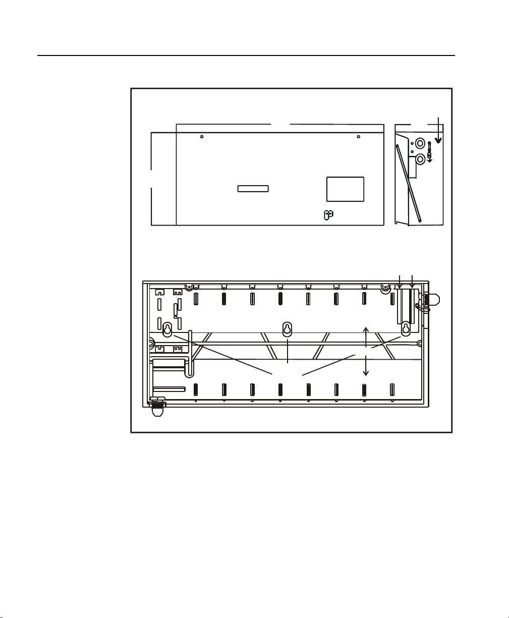
1. The Eight-card Shelf
The Eight-card Shelf, model 751109/13, is used indoors to accommodate eight
service cards. The shelf is molded from specially treated polyurethane, making it
a lightweight, flame retardant product of high dielectric strength. Its polyurethane
body limits the possibility of many kinds of infiltration while providing reliable
isolation from external ground potentials.
The shelf is equipped with the connectors required for any of the plug-in cards
from the Teleline line of products. In addition, the shelf has a separate area to
accommodate a Power Supply Card, model 751313 (120 V ac/130 V dc),
751324 (24 V dc), or model 751316 (-48 V dc), and a Battery Backup Card,
model 751312 to provide an uninterruptible power supply (UPS). If the Battery
Backup is not used, then two Power Supply Cards may be installed for
redundancy.
The shelf is shipped with a station cable stub for connection to communications
equipment, a Polyolefin Insulated Cable (PIC) stub for connection to the Central
Office (CO) incoming cable, and a power cable.
The shelf’s features include the following:
• The station and CO cables connect to the shelf via individual printed circuit
boards.
• Each of the five card slots can accommodate two Tip and Ring pairs for
four-wire AC data applications, four-wire T1 applications, HDSL and ADSL
applications.
• The station and CO cables are prewired to male connectors for insertion into
the female receptacles mounted on the printed circuit boards inside the shelf.
The power cable provided is used to supply 120 V ac to the shelf when an
internal Power Supply Card is used. The cable may also be used for V dc
applications if the three-prong plug is removed.
• The shelf has been successfully tested for the UL standard (94V0) for flame
retardance.
• The unit is lightweight and easy to install. The weight of the shelf with the
motherboards is 22 lbs (9.95 kg).
• The enclosure resists the infiltration of dust, mist, and water from sprinklers.
For a view of the Eight-card Shelf, refer to Figure 1.