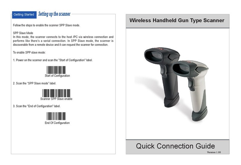
POSline SC2110 User manual

Manual POSline
SC2110/SC2120/SC2130/SC2140
1D & 2D Barcode Reader User's

Introducción
Instalación Interfase Teclado
1) En primer lugar, debe apagar la terminal o computadora.
2) Desconecte el teclado de la computadora.
3) Conecte el cable correspondiente al lector y a la computadora.
4) Encienda la computadora.
Instalación Interfase RS-232
1) Desconecte la energia electrica de la terminal o computadora.
2) Conecte el cable serial y la fuente de poder externa al lector.
3) Coloque el conector en el puerto serial de la computadora.
Apriete los dos tornillos para asegurar el conector al puerto.
4) Coloque la fuente de poder a la energia electrica.
5) Una vez que el lector ha sido totalmente conectado, encienda la
terminal o computadora.
Nota: Si alguno de los pasos anteriores se hace incorrectamente,
desconecte la energia electrica inmediatamente y revise si hay
alguna conexion inadecuada. Vuelva a empezar.

Programando los lectores
SC2110/SC2120/SC2130/SC2140
Para programar los modelos SC2110/SC2120/SC2130/SC2140, usted debera
escanear una serie de codigos de barras en el orden indicado. Doble
hacia fuera la cubierta de la parte posterior y usted vera una tabla de
codigos de barra alfanumericos, los cuales son utilizados para
programar las diferentes opciones presentadas.
Para programar cada opción, usted deberá:
1. Escanear el Program de codigo de barras de las tablas de
configuracion de parametros.
2. Seleccione el modo de opcion seleccionado Option Barcode.
(tambien en las tablas de configuracion de parametros).
3. En la parte derecha de la opcion codigo de barras, estan instaladas
las entradas alfanumericas necesarias. Escanee esas entradas de la
ultima pagina del manual. Para confirmar los pasos anteriore s
debera escanear el codigo de barras Finish.
4. Una vez que ha terminado de programar, escaneee el codigo de
barras Exit, enlistado en la parte inferior derecha de cada tabla de
configuracion de parametros.

Seleccion de Interfase
Los lectores SC2110/SC2120/SC2130/SC2140 soportan las siguientes
interfases: Teclado, Rs-232 Serial y USB. En la mayoria de los casos,
basta con conectar el cable apropiado para seleccionar la interfase
deseada.
Seleccion de Interfase: Usted puede cambiar la interfase que el
fabricante indica por default. Conectando diferentes cables y
configurando la interfase correcta, entonces el lector operara con esa
interfase. Sin embargo, debe de estar seguro del cable que necesita.
*La intefase de fabrica del lector SC2110 no puede ser cambiada por otro
tipo de interfase, cada modelo especifico trabaja solo con su interfase.
Teclado/RS232/USB Auto deteccion: Configurando esta funcion el
lector seleccionara la interfase Teclado o RS232 o USB.
Program
Option Bar Code Option Alphanumeric Entry
Interface selection
Keyboard Wedge
RS-232
Wand emulation
USB
Keyboard/RS232
Auto detection
Reserved
00
01
02
03
04 *
05
Exit
Note: *-Default.

Teclado wedge
La interfase a Teclado del lector, soporte la mayoria de las terminales
PC e IBM. El proceso de instalacion es bastante sencillo, no requiere
cambios de software o hardware
Tipo de Teclado: Seleccione el tipo de conector del teclado de su
computadora. Debera seleccionar el cable adecuado al lector.
Formato del Teclado: La seleccion del formato del teclado permite
varios lenguajes aparte del ingles de USA. Primero necesita confirmar
que lenguaje requiere. En DOS, utilice el comando “keyb” para
seleccionar el formato de teclado o en WINDOWS en “Control Panel”
en la carpeta “keyboard” seleccione la opcion “language”. Para
mayores detalles, consulte su manual de usuario DOS o WINDOWS.
Velocidad del Teclado: Por seleccion, usted puede cambiar la velocidad
del lector indicada en la computadora. Regularmente marcando 00 o
01 para trabajo con alta velocidad. Si se pierden algunos caracteres en
la captura, debera marcar 05 o 06 en la velocidad del teclado de la
computadora.

Program
Option Bar Code Option Alphanumeric Entry
Keyboard type
IBM AT, PS/2
IBM PS/2 25,30
IBM PS/2 25
IBM XT
IBM 5550
Macintosh ADB
NEC 9801
00 *
01
02
03
04
05
06
Keyboard layout
USA
Belgium
Danish
France
Germany
Italian
Portuguese
Spanish
Swedish
Switzerland
UK
Latin American
00 *
01
02
03
04
05
06
07
08
09
10
11
Keyboard speed
0-8
0 : high clock rate
8 : low clock rate
00-08
01 *
Exit

Keyboard wedge
Function Key: Set Enable, scanner can output code as pressing function-key in your
application program while the barcode datas contain ASCII value between 0116 to 1F16.
Refer to ASCII table, page 71.
Numeric Key: The Keypad has to be selected if your application program is only keypad
numeric code acceptable. So, scanner will output code as press numeric keypad when it
read numeric digit. (The keypad is in the right side of keyboard, and Num Lock control
key is also on.) If Alt+Keypad is selected, Caps Lock and output will be independent.
Caps Lock: By selecting Caps Lock or No Caps Lock, scanner can get Caps Lock status.
Power-on simulation: All of the PCs check the keyboard status during power-on selftest.
It is recommended to Enable function if you are working without keyboard installation. It
simulates keyboard timing and pass keyboard present status to the PC during power-on.
Inter-character delay: This delay is inserted after each data characters transmitted. If
the transmission speed is too high, the system may not be able to receive all characters.
Adjust it and try out suited delay to make system work properly.
Block transmission delay: It is a delay timer between barcode data output. The feature
is used to transfer continually with shorter barcode data or multi-field scanning.

Program
Option Bar Code Option Alphanumeric Entry
Function key
Disable
Enable
00 *
01
Numeric key
Alphabetic key
Numeric keypad
Only
Alt+Keypad
00 *
01
02
Caps lock
Caps lock
No Caps lock
00
01 *
Power-on simulation
Disable
Enable
00 *
01
Inter-character delay
00-99 msec 00-99
02 *
Block transmission delay
00-99 10 msec 00-99
10 *
Exit

RS-232
CTS: Clear To Send (Hardware Signal)
RTS: Request To Send (Hardware Signal)
Xon: Transmit On (ASCII Code 1116)
Xoff: Transmit Off (ASCII Code1316)
Flow control:
None-The communication only uses TxD and RxD signals without regard for any
hardware or software handshaking protocol.
RTS/CTS-If the scanner wants to send the barcode data to host computer, it will issue
the RTS signal first, wait for the CTS signal from the host computer, and then perform
the normal data communication. If there is no replied CTS signal from the host
computer after the timeout (Response Delay) duration, the scanner will issue a 5
warning beeps.
Xon/Xoff- When the host computer is unable to accept data, it sends a Xoff code to
inform the scanner to suspend data transmission, and Xon to continue.
ACK/NAK- When the ACK/NAK protocol is used, the scanner waits for an ACK
(acknowledge) or (not acknowledge) from the host computer after data transmission,
and will resend in response to a NAK.
Inter-character delay: It is delay time between data character’s data output. It is also
same as Inter-char. delay of keyboard wedge.
Block transmission delay: It is a delay time between barcode data output. It is also
same as Block transmission delay of keyboard wedge.
Response delay: This delay is used for serial communication of the scanner to waiting
for handshaking acknowledgment from the host computer.
Program
Option Bar Code Option Alphanumeric Entry
Flow control
None
RTS/CTS
Xon/Xoff
ACK/NAK
00 *
01
02
03
Inter-character delay
00-99 (msec) 00-99
00 *
Block transmission delay
00-99 (10 msec) 00-99
00 *
Response delay
00-99 (100 msec) 00-99
20 *
Baud rate
300 BPS
600 BPS
1200 BPS
2400 BPS
4800 BPS
9600 BPS
19200 BPS
38400 BPS
00
01
02
03
04
05 *
06
07
Parity
None
Odd
Even
00 *
01
02
Data bit
8 bits
7 bits
00 *
01
Stop bit
One bit
Two bits
00 *
01

Exit
Scan
Scanning mode:
Good-read off-The trigger button must be pressed to activate scanning. The light source
of scanner stops scanning when there is a successful reading or no code is decoded
after the Stand-by duration elapsed.
Momentary-The trigger button acts as a switch. Press button to activate scanning and
release button to stop scanning.
Alternate-The trigger button acts as a toggle switch. Press button to activate or stop
scanning.
Timeout off-The trigger button must be pressed to activate scanning, and scanner stops
scanning when no code is decoded after the
Stand-by duration elapsed.
Continue-The scanner always keeps reading, and it does not matter when trigger button
is pressed or duration is elapsed.
Test only-The scanner always keeps a constant reading and same label reading is
allowed without double confirm. The feature can test the performance of scanner for
reading speed and sensitivity.
Stand-by duration: A timeout duration of 1 to 99 seconds can be adjusted. The Stand-by
duration that is valid scanning duration. It is only effective when the scanning mode of
CCD is operated in Timeout off mode, and Good-read off mode.
Same Barcode delay time: If the barcode has been scanned twice, then only the first
barcode will be accepted.
Double confirm: If it is enabled, the scanner will require a several times successful
decoding to confirm the barcode data. The more confirming times required the more
inhibitive miss-reading code will be shown. If you set Double confirm, the Multi field
scan Enable function won’t be able to work.

Multi field scan: The scanner can be read many sets of barcode data on the same
scanning line at the same time, even if they are different kinds of barcode symbology.
Program
Option Bar Code Option Alphanumeric Entry
Scanning mode
Good-read off
Momentary
Alternate
Timeout off
Continue
Test only
00
01 *
02
03
04
05
Stand-by duration
01-99 (second) 01-99
10 *
Same barcode delay time
01-99 (10 msec) 01-99
50 *
Double confirm
0- 09
(00: no double
confirm)
0- 09
00 *
Multi field scan
Disable
Enable
00 *
01
Exit

PDF-417
Only the SC2130 can decode PDF-417.
Truncate leading/ending: Refer to Truncate leading/ending of UPCA.
Code Id setting: Refer to Code ID setting of UPCA.
Insertion group selection: Refer to Insertion group selection of UPCA.
Program
Option Bar Code Option Alphanumeric Entry
Read
Disable
Enable
00 *
01
Truncate leading
0-15 00-15
00 *
Truncate ending
0-15 00-15
00 *
Code ID setting
00-ffH ASCII code 00-ffH
<>
Insert group selection
00-44 00-44
00 *

Parameter Setting List
Program
Barcode standard parameter setting list
If you wish to display the current configuration
of your SC2110/SC2120/SC2130, scanner over
the host terminal/computer, scan the Barcode standard
parameter setting list bar code.
System parameter setting list
If you wish to display the product information and revision
number for your SC2110/SC2120/SC2130 scanner over the
host
terminal/computer, scan the System parameter setting list
bar code.
String setting list
If you wish to display the string format list, scan the String
setting list bar code.
Unique parameter list
If you wish to display the unique parameter setting list,
scan the Unique parameter list bar code.

Firmware version list
If you wish to display the firmware version, scan the
Firmware version list.
WARNING: Default value initialization
If you wish to return the
SC2110/SC2120/SC2130/SC2140 to all the factory
default settings, scan the Default value initialization bar
code.

0
A
B
C
D
E
F
Finish
1
2
3
4
5
6
7
8
9
This manual suits for next models
3
Table of contents
Other POSline Barcode Reader manuals

POSline
POSline SM2410B User manual

POSline
POSline SC2160W User manual

POSline
POSline SL2050 User manual

POSline
POSline SC2100B Owner's manual

POSline
POSline SM2430 User manual

POSline
POSline SC2120B User manual

POSline
POSline SM2410 User manual

POSline
POSline SM2410 User manual

POSline
POSline SW2500 User manual

POSline
POSline SM2440 User manual
Popular Barcode Reader manuals by other brands

Emona Instruments Pty Ltd
Emona Instruments Pty Ltd BCS-OPT quick start guide

Argox
Argox Xellent X-3200ZE user manual

Pronto
Pronto 474 user manual

Datalogic
Datalogic PowerScan 9500 Series Product reference guide

Honeywell
Honeywell MK3780-71A38 Technical specifications

Godex
Godex EZPi1000 Series user manual