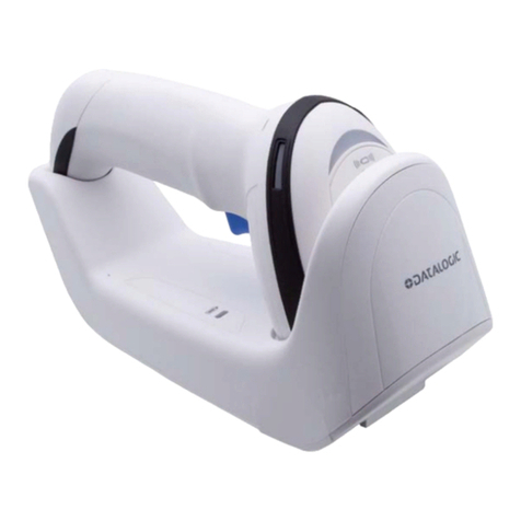
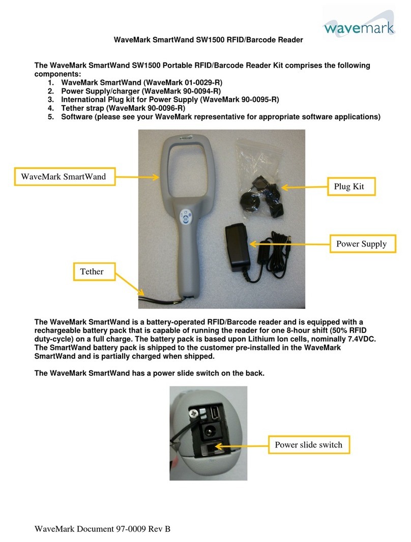
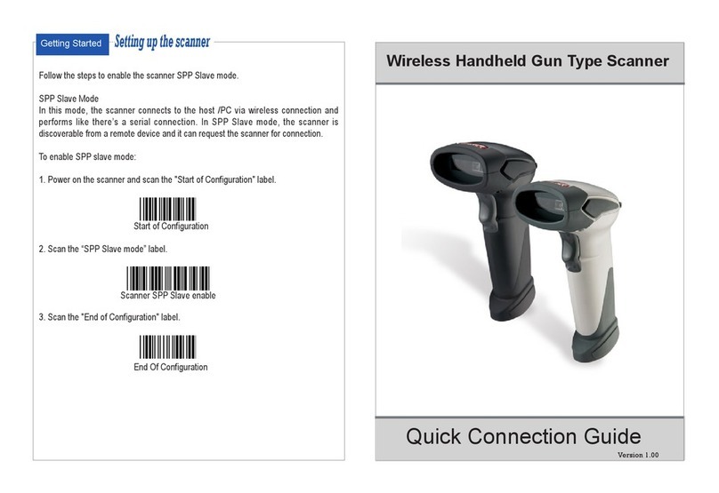
POSline SW2500 User manual

Programming Manual
SW2500
WIRELESS SCANNER
Product specications are subject to change without notice.

NOTICE
This equipment has been tested and found comply with the limits
for a Class A digital device, pursuant to part 15 of the FCC Rules.
These limits are designed to provide reasonable protection against
harmful interface when the equipment is operated in a commercial
environment. This equipment generates, uses, and can radiate
radio frequency energy and, if not installed and used in accordance
with the instruction manual, may cause harmful interface to radio
communications. Operation of this equipment in a residential area
is likely to cause harmful interface in which case the user will be
required to correct the interface at his own expense.
(All brand and trademark are belonged to their respective owner.
(Specifications are subject change without notice.
This device complies with part 15 of the FCC
Rules. Operation is subject to the following two
condition: (1) This device may not cause
harmful interface, and (2) This device must
accept any interface received, including
Interface that ma
y
cause undesired o
p
eration.
1

Operation Manual
2

Index
1 Instroduction 4
Installation4
Recommended Steps 4
Configuration Flowchart 5
String Output Flowchart5
Default Setting 6
Manual Label Layout 7
Frequent Question 8
2 Interface 10
Host Interface 10
Keyboard Wedge 11
RS-232C15
Wand Emulation (Linker or Pen)18
OCIA 20
3 System Control21
4 Code Option 26
UPC-A26
UPC-E28
EAN-13 (ISBN/ISSN) 30
EAN-8 32
CODE-39 (CODE-32) 34
Interleaved 2 of 5 (Odd S-code) 36
Industrial 2 of 538
Matrix 2 of 5 40
China Post 2 of 5 42
Codabar/NW7 44
Code-128 46
Code-93 48
Code-11 50
MSI/Plessey 52
UK/Plessey 54
Telepen 56
IATA 58
5 String Format60
Preamble/Postamble 60
Prefix/Suffix 61
Character Insertion62
Other Control 64
6 Cable Type66
7 Test Chart68
8 ASCII Code/Hexdecimal Table71
3
Installation
1) First of all, you must make sure that the power is disconnected
form your equipment before connecting the scanner. Beside, you
also have to check the cable connector of the scanner match
your equipment interface correctly.
2) Boot up your computer after connecting the scanner with your
equipment, the scanner will make a long music and light the LED,
above scanner to indicate a successful power on. Trigger the
button, the scan line in front of scanner will active. Now you can
start to set programming optimal usage.
(If any of the above operation is not right, turn off the power
immediately and check any improper connections. Go through all
above steps again.
Recommened Steps
When the required settings have been configured, all settings
are stored in non volatile memory of scanner after reading EXIT
label. There are recommended steps as follows.
1) Set right host interface for your scanner at
10.
(The scanner is in factory default as bold label)
2) Set interface to optimize protocol of scanner with your host in
Charter 2.
3) Set system control of scanner, such as specific adjustments
double confirm, power saving, indicator and scanning mode
which you prefer usage in Chapter 3.
4) Set code option of scanner for your usage in Chapter 4. You
must make sure to enable the symbology first, then Min./Max.
code length, code ID checksum and truncate digits are also
convered.
5) Set string format of the scanner, such as preamble, postamble,
prefix, suffix, code ID and code name transmission for your
application in Chapter 5.
(If any of the error step is processing, scanner will generate a 5
wanrrying beeps to indicate an invaild setting. You have to take
care this matter and set correctly again.
(If still not work properly. Please contact with dealer.
Operation Manual
4

Configuration Flowchart
String Output Flowchart
Preamble
Prefix
Code Name
Code ID
Code Data
C
o
d
e
L
eng
th
Suffix
Postamble
E
n
t
er
Programming
Mode
Fi
n
i
s
h
ASCII
Code or Decimal
Value Setting
Select Function
Label
Interface Default Exit & Interface Default
Function
PROGRAM
Decimal
(10's Value)
Hexdecimal
(High Byte)
Decimal
(1's Value)
Hexdecimal
(Low Byte)
SET
EXIT
A
BORT
V
ERSION DATE
SETTING LIST
DEFAULT
P
re
fi
x or
Suffix
Ol
Set ASCII Code Set Decimal Value
Exit With Save
Exit Without Save
Exit & Default
Exit & Version
Exit & Settin
g
List
5
Introduction
1

Default Setting
Length TruncateCode
Type Read
Enable Min. Max. Leading Ending Code
ID
UPC-A 3- - 0 0 A
UPC-E 3- - 0 0 E
EAN-13 3- - 0 0 F
EAN-8 3- - 0 0 FF
Code-39 30 0 0 0 M
Interleaved 2 of 5 6 0 0 0 I
Industrial 2 of 5 4 0 0 0 H
Matrix 2 of 5 4 0 0 0 G
China Post 2 of 5 11 11 0 0 J
Codabar/NW7 34 0 0 0 N
Code-128 30 0 0 0 K
Code-93 4 0 0 0 L
Code-11 4 0 0 0 O
MSI/Plessey 4 0 0 0 P
UK/Plessey 4 0 0 0 R
Telepen 4 0 0 0 S
IATA 4 0 0 0 Q
Adjustment Value Result
Beep Loudness 05 Level 5
Beep Tone 24 2.4 KHz
Beep Duration 06 60 mSec
Beep Tone1 12 1.2 KHz
Beep Duration1 06 60 mSec
Stand-by Time 15 15 Sec
Active Time 20 200 mSec
Sleep Time 20 200 mSec
Good-read Delay 50 500 mSec
Double Confirm Times 01 Once
Inter-char. Delay 01 1 mSec
Transmit Delay 00 0 mSec
Response Delay 30 3 Sec
Add-on Wait Time 50 500 mSec
Margin Delay 10 100 mSec
Preamble Data1 0016 <NULL>
Preamble Data2 0016 <NULL>
Postamble Data1 0D16 <CR>
Postamble Data2 0A16 <LF>
Prefix Data (All Datas) 0016 <NULL>
Suffix Data (All Datas) 0016 <NULL>
Add-on Insertion (All Datas) 0016 <NULL>
Insertion1-4 (Position & All Datas) 0016 <NULL>
Concatenation Data 2916 <GS>
Operation Manual
6

Manual Label Layout
The scanner must be set by reading the barcode labels in
manual. The discription of label is as follows.
(The factory default settings are indicated by bold symbols.
Disable DZA
*DZA*
Enable DZB
*DZB*
S
p
are Function
Disable DYA
*DYA*
Enable DYB
*DYB*
Truncate Leading BAO
*BAO*
(Range:0010-1510)
Truncate Ending BAP
*BAP*
(Range:0010-1510)
Code ID AAA
*AAA*
(Range:0016-FF16 ASCII Code)
Specific
A
d
j
ustments
Truncate Leadin
g
Zero
EXIT
UPC-A
*/$%END*
Code Option
4
Truncate Leading / Ending: The
leading or ending digits of barcode
data characters can be truncated
when these values are set to non
zero. It will be read nothing else onl
y
beeps when the truncate value is
more than barcode data digits or the
value of Truncate Leading is overlap
with the Ending. The maximum value
of Truncate digits is 15.
Code ID: A Code ID is a character
27
Section
Title Exit
Program
Command
For RS-232C
Selection
Label
Default
Setting
Selection
Description
Chapte
r
Number
Chapte
r
Title
Page
Number
Function
Title
A
djustment
(ASCII Code or
Decimal Value)
Group
Line
Selection
Label
Range
Description
Function
Description
7
Introduction
1

Frequent Question
Q: Why scanner block the keyboard operation?
A: Check the cable connection with your equipment, then turn
power on again.
Q: If scanner has a good read beep but nothing transferring
after read a label.
A: Using the SETTING LIST at
10 to show what current setting of
scanner is, or reset to Default, (or select right Interface default if
scanner to be change another interface used), then re-program
scanner again.
Q: If scanner dosen't need an Enter character addition after
each barcode label transmission.
A: Refer to postamble transmission at
60, then set Disable.
Q: If scanner needs to read single digit code.
A: Refer to Min. code length of code option use "01" in Chapter 4
for single code readable.
Q: If scanner isn't able to discriminate an unknown label, but
read manual very well.
A: Refer to code name at
64 to set Enable, read a barcode label,
then you will know what symbology is read. Beside, it maybe
need to verify checksum. Refer to verify checksum of code
option in Chapter 4, and set Enable.
Q: If scanner transfers character very slow or loses some
characters on screen in keyboard interface after reading a
label.
A: You may set caps lock to be Alt+Keypad at
11. Otherwise, it
maybe mis-match of transmission rate, therefore, you can adjust
an appropriate Inter-char. Delay to match your equipment. See
11.
Q: If scanner want to read a label as function key for your
apprication.
A: Refer to function key simulation at
11 and set Enable, then
scanner can transmit a code as function key. It is used for
keyboard interface only. Beside, you must make sure that a label
is encoded as function key, and its ASCII code is from 0016 to
1F16 You can refer to ASCII code table at
71.
Operation Manual
8

Q:Could I change scanner into different type interface directly?
A: You can change factory interface default for other type interface.
By plug different cable, program scanner and set right interface
to exit, then the scanner will be change to another interface.
However, you must make sure what cable you need. Refer
Cable Type to 66, 67.
Q: How to configure scanner via RS-232C?
A: Next to the selection description, you will find a frame command,
such as AAB. These commands can be sent to scanner with
RS-232C interface. You must make sure that scanner is the
same protocal as your equipment of RS-232C, and light source
of scanner has been actived by pressing button.
Example Beep Loudness Level "10", Good-read Beep "Enable"
To configure the reguired commands proceed as follows:
Send as: <ESC>(1B16) BCommand(s) B<CR>(0D16)
Send <ESC>BBAC B
%01 B
%00 B
%OK B
CEB B
<CR>
︸
︸
︸
︸
︸
Beep 1 0 SET Good-read
Londness Level Beep Enable
(Call to the dealer if scanner dose not work properly.
9
Introduction
1

You can change factory
interface default for other type
rface. By plug different
le, program scanner and
set right interface to exit, then
e scanner will be change to
nother interface. However,
you must make sure what
cable you need. Refer Cable
ype to
66, 67.
inte
cab
th
a
T
DEFAULT: All settings are
set as bold label, but
xclude interface setting.
re
e
VERSION DATE: You can get
e software date of decoder
n screen. It is important for
maintanace.
th
o
S
re
ETTING LIST: First it is
commended that you need
to excute a text editor
program (such as PE2 and
rd) for keyboard interface,
xcute a terminal program
(such as Hyper Terminal) for
RS-232. Then scanner will transmit current settings on screen.
Wo
or e
ABORT: If you have a mis-setting or want to skip this current
configuration during you are programming, using this function, all
front settings are aborted before you set EXIT to finish
programming.
(Programming will be finished while each label of miscellany is
read.
Interface Default
DEFAULT (without Interface)
*/$%DEF*
VERSION DATE
*/$%VER*
SETTING LIST
*/$%LST*
ABORT
*/$%ESC*
Miscellan
y
Keyboard Wedge
*/$%C00*
RS-232C
*/$%C01*
WAND EMULATION
*/$%C02*
OCIA
*/$%C03*
Spare Interface
*/$%C04*
PROGRAM
*/$%STR*
Host Interface
Operation Manual
10

Low CZA
*CZA*
Medium CZB
*CZB*
High CZC
*CZC*
Turbo CZD
*CZD*
Numeric Key Position
Caps Lock
Keyboard Speed
By selecting, you can change output
speed of scanner to advance or match
with host computer. Generally, set
High or Turbo in working high
performance. If some output
characters of barcode have been lost
or shown on screen slowly, you may
need to set Medium or Low to match
your host keyboard speed.
Function Key Simulation
Set Enable scanner can output code
as pressing function-key in your
application program while the barcode
datas contain ASCII value between
0116 to 1F16.. See
60 and Refer to
ASCII table
71 at grey area. You'll
find function-keys withASCII codes.
The Keypad have to selecte if your
application program is only keypad
numeric code acceptable. So, scanner
will output code as press numeric
key-pad when it read numeric digit.
(The keypad is in the right side of
keyboard, and Num Lock control key
is also on.)
By selecting Uppercase or Lowercase,
scanner can get Caps Lock status. If
Alt+Keypad is selected, Caps Lock and
output will be independent.
Example Barcode "ABCdef"
Status
Selection Caps Lock
On Caps Lock
Off
Uppercase ABCdef abcDEF
Lowercase abcDEF ABCdef
Alt+Keypad ABCdef ABCdef
Alphabetic-key DAA
*DAA*
Keypad DAB
*DAB*
Uppercase DDA
*DDA*
Lowercase DDB
*DDB*
Alt+Keypad DDD
*DDD*
Disable DBA
*DBA*
Enable DBB
*DBB*
EXIT
Keyboard Wedge
*/$%END*
11
Interface
2

Keyboard Simulation All of the PCs check the keyboard
atus during power-on selftest. It is
commended to
st
re Enable the function if
you are working without keyboard
stallation. It simulates keyboard
ing and pass keyboard present
status to the PC during power-on.
in
tim
Spare Function
Specific Adjustments
BAL Inter-char. Delay
*BAL*
(Range:0010-9910 Unit:1ms)
BAM Transmit Delay
*BAM*
(Range:0010-9910 Unit:10ms)
Inter-char. Delay: This delay is
inserted after each data characters
transmitted.If the transission speed is
too high, the system may not be able
to receive all characters. Adjust it and
try out suited delay to makes system
work properly.
Transmit Delay: It is a delay timer
between barcode data output. The feature is used to transfer
continually with shorter barcode data or multi-field scanning.
Example Barcode Data: "ABCD" Inter-char. Delay: 2ms
TransmitDelay:10ms
1) PROGRAMBEntry Programming
2) Inter-char. DelayB0B2BSETB2ms Inter-char. Delay
︸
02*1ms(Unit)=2ms
3) Transmit DelayB0B1BSETB10ms Transmit Delay
︸
01*10ms(Unit)=10ms
4) EXIT Exit Programming
Output
A 2ms B2ms C2ms D 2ms 10ms
DEA Disable
*DEA*
DEB Enable
*DEB*
DCA Disable
*DCA*
DCB Enable
*DCB*
PROGRAM
*/$%STR*
Keyboard Wedge
Operation Manual
12

Select keyboard type connector of
your host computer. Scanner must be
selected to the appropriate host
interface cable converter. Refer to
Cable Type at
66.
IBM AT,PS/2 DFA
*DFA*
IBM XT DFB
*DFB*
Macintosh ADB. DFC
*DFC*
IBM PS/2 25,30 DFD
*DFD*
NEC 9801 DFE
*DFE*
IBM PS/2 55 DFF
*DFF*
IBM 5550 DFG
*DFG*
KT 106 DFH
*DFH*
IBM 5576 DFI
*DFI*
Spare1 DFJ
*DFJ*
Spare2 DFK
*DFK*
Spare3 DFL
*DFL*
Spare4 DFM
*DFM*
Keyboard Type
EXIT
Keyboard Wedge
*/$%END*
13
Interface
2

Keyboard Layout The selecting of keyboard layout
pports many country languages
her than USA keyboard layout. First
you need to confirm country langage
at you desire. In DOS, using
mmand "Keyb" to selecte the
desirable keyboard layout or in
INDOWS entry "Control' then pop
eyboard" to selecte country at
"language" item. For details, please
fer to your DOS or WINDOWS
er's manual.
su
ot
th
co
W
"K
re
us
DGA USA (US)
*DGA*
DGB Belgium (BE)
*DGB*
DGC Danish (DK)
*DGC*
DGD France(FR)
*DGD*
DGE Germany (GR)
*DGE*
DGF Italian (IT)
*DGF*
DGG Portuguese (PO)
*DGG*
DGH Spanish (SP)
*DGH*
DGI Swedish (SV)
*DGI*
DGJ Switzerland (SF)
*DGJ*
DGK UK (UK)
*DGK*
DGL Latin American (LA)
*DGL*
DGM Japan
*DGM*
DGN Spare2
*DGN*
PROGRAM
*/$%STR*
Keyboard Wedge
Operation Manual
14

Handshaking Protocol
CTS: Clear To Send (Hardware Signal)
RTS: Request To Send (Hardware Signal)
STX: Start Of Text (ASCII Code 0216)
ETX: End Of Text (ASCII Code 0316)
Xon: Transmit On (ASCII Code 1316)
Xoff: Transmit Off (ASCII Code 1116)
Disable: The communication only
uses TxD and RxD signals without
regard for any hardware or software
handshaking protocol.
RTS/CTS (CTS/RTS): If the scanner
wants to send the barcode data to
host computer, it will issue the RTS
(CTS) signal first, wait for the CTS
(RTS) signal from the host computer,
and then perform the normal data
communication. If there is no replied
CTS (RTS) signal from the host
computer after the timeout (Response
Delay) duration, the scanner will issue
a 5 warning beeps.
Scanner Ready: The scanner will
active the RTS signal after power-on,
and will transmit data upon receiving
active CTS signals.
Data Ready: The scanner will active the RTS signal to indicate a
successful decoding and will transmit data upon receiving CTS
signals.
STX/ETX: The STX and ETX are used to pack barcode together in
the normal data transmission.
Xon/Xoff: When the host computer is unable to accept data, it
sends an Xoff code to inform the scanner to suspend data
transmission,and Xon to continue.
CTS Trigger: This operation enabled an external device to control
scanning. The CTS trigger is controlled by applying an external
trigger signal to the CTS input. When active, this signal causes
scanning to begin as if the scanner's trigger was depressed. In the
event of decoding, the trigger signal must be deactivated for a
minimum of 50ms before another scan can be attempted.
Disable DLA
*DLA*
RTS/CTS DLB
*DLB*
CTS/RTS DLC
*DLC*
Scanner Ready DLD
*DLD*
Data Ready DLE
*DLE*
Xon/Xoff DLF
*DLF*
STX/ETX DLG
*DLG*
CTS Trigger DLH
*DLH*
Spare DLI
*DLI*
EXIT
RS-232C
*/$%END*
15
Interface
2

Baud Rate
Data Parit
y
DHA 38400 Bps
*DHA*
DHB 19200 Bps
*DHB*
DHC 9600 Bps
*DHC*
DHD 4800 Bps
*DHD*
DHE 2400 Bps
*DHE*
DHF 1200 Bps
*DHF*
DHG 600 Bps
*DHG*
DHH 300 Bps
*DHH*
DKA None
*DKA*
DKC Even
*DKC*
DKD Odd
*DKD*
DKE Space
*DKE*
DKF Mark
*DKF*
PROGRAM
*/$%STR*
RS-232C
Operation Manual
16

Inter-char. Delay: It is delay time
between data character's output. It is
same as Inter-char. Delay of keyboard
wedge, see
12.
Transmit Delay: It is a delay time
between barcode data output. It is
also same as Transmit Delay of
Keyboard wedge, see
12.
Response Delay: This delay is used
for serial communication of the
scanner to waiting for handshaking acknowledgment from the host
computer. If scanner doesn't get any acknowledgments form host
after the timeout occurs, it will issue 5 warning beeps.You may
check handshanking mode or adjust a longer delay timer. The
feature is particularly useful for some applications that the host
computer takes a longer time to respond.
Specific Adjustments
Inter-char. Delay
BAL
*BAL*
(Range:0010-9910 Unit:1ms)
Transmit Delay
BAM
*BAM*
(Range:0010-9910 Unit:10ms)
Response Delay BAN
*BAN*
(Range:0110-9910 Unit:100ms)
Stop Bits
One Bit DIA
*DIA*
Two Bits DIB
*DIB*
Data Bits
7 Bits DJA
*DJA*
8 Bits DJB
*DJB*
EXIT
RS-232C
*/$%END*
17
Interface
2

Active Level Bar Hi/Space Lo: Black will be
nsmited as a high voltage level
5V) and space as low level (0V).
tra
(+
B
tra
ar Lo/Space Hi: Black will be
nsmited as a low voltage level (0V)
and space as high level (+5V).
Normal Level You must make sure what is
ormal Level of your wand decoder
vice in stand-by (idle). So, initial
signal state as a
N
de High voltage level
(+5V) or Low voltage level (0V).
Output Speed
Narrow/Wide Ratio
DOA Low
*DOA*
DOB Medium
*DOB*
DOC High
*DOC*
DOD Turbo
*DOD*
This setting is same as serial
transmission baud rate, and it must be
approbated your wand decoder
resolution. The unit of speed is a width
of minimum narrow bar.
Output
Speed Bps
(bits per second)
Low 1200
Medium 2400
High 4800
Turbo 9600
The setting is applied two kinds of
tio barcode symbologies with
rrow and wide only, such as
Code-39, Interleaved 2 of 5, Codabar,
essey and IATA...etc. So, it will be
nored if some kinds of barcode
symbologies, such as EAN, UPC, and
ode-128, are read. This setting is
le to adjust appropriate signal width
during transmitting the bar image. The
tio allows to adjust from
ra
na
Pl
ig
C
ab
ra 1:2 to 1:3.5,
but upon your wand decoder device.
DMA Bar Hi/Space Lo
*DMA*
DMB Bar Lo/Space Hi
*DMB*
DNA Low
*DNA*
DNB High
*DNB*
DQA 1:2
*DQA*
DQB 1:2.5
*DQB*
DQC 1:3
*DQC*
DQD 1:3.5
*DQD*
PROGRAM
*/$%STR*
Wand Emulation
Operation Manual
18

Discrete codes such as Code-39 and
Codabar are featured an Inter-Char. Gap
between two characters of barcode. It
makes them suitable for printing in the
Narrow or Wide gap by mechanical
numbering system. You can choice one suit
your decoder.
Generally, wand emulation Output
signals same as symbology when it
read a barcode. By setting, the
scanner can read many kinds of
barcode symbologies, but transmitted
as code-39 full ASCII format, even
your decoder device no support them.
Margin Delay: It is a timer of zone
like space zone of barcode label
margin. The width of margin time will
be added before and after in each
barcode data automatically when it is
transmitted.
Transmit Delay: It is a delay time
between barcode data output. It is the same as Transmit Delay of
keyboard wedge, see
12.
Example Normal Level: Low, Bar Lo/Space Hi
Barcode Pattern
……5v
Normal Low 0v
︸
︸
Margin Delay Margin Delay
Inter-char. Gap
Narrow DPA
*DPA*
Wide DPB
*DPB*
Code-39 Simulation
Disable DRA
*DRA*
Enable DRB
*DRB*
Specific Adjustments
Margin Delay BAL
*BAL*
(Range:0010-9910 Unit:10ms)
Transmit Delay BAM
*BAM*
(Range:0010-9910 Unit:10ms)
EXIT
Wand Emulation
*/$%END*
19
Interface
2
Table of contents
Other POSline Barcode Reader manuals

POSline
POSline SM2410B User manual

POSline
POSline SM2430 User manual

POSline
POSline SL2050 User manual

POSline
POSline SC2160W User manual

POSline
POSline SC2100B Owner's manual

POSline
POSline SM2450 User manual

POSline
POSline SC2120B User manual

POSline
POSline SM2410 User manual

POSline
POSline SM2440 User manual

POSline
POSline SM2410 User manual