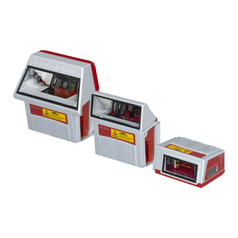
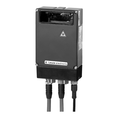
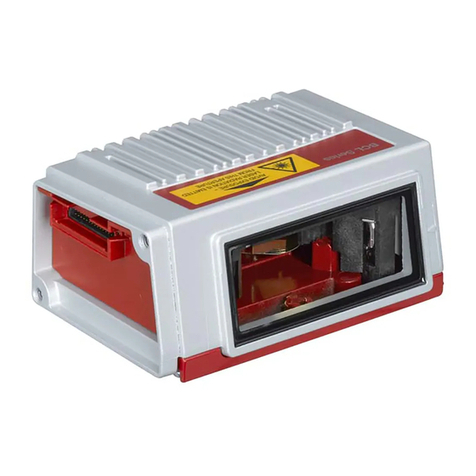
Leuze BCL 900i User manual

BCL 900i
Barcode Scanner
Original operating instructions
EN 2015/10 - 50130069
Subject to change
without prior notice

iii
CONTENTS
REFERENCES .........................................................................................................vii
Reference Documentation ........................................................................................ vii
Support Through the Website ................................................................................... vii
Patents ..................................................................................................................... vii
CONVENTIONS.......................................................................................................viii
COMPLIANCE.........................................................................................................viii
Electrical Safety........................................................................................................viii
Laser Safety..............................................................................................................viii
Warning and Serial labels ..........................................................................................ix
Power Supply..............................................................................................................x
CSA Listing.................................................................................................................x
CE Compliance...........................................................................................................x
FCC Compliance........................................................................................................xi
GENERAL VIEW ......................................................................................................xii
1INTRODUCTION ........................................................................................................1
1.1 Product Description.....................................................................................................1
1.2 Applications ................................................................................................................1
1.3 Model Description.......................................................................................................2
1.4 BCL 900i versions.......................................................................................................2
1.5 Human Machine Interface...........................................................................................3
1.6 Accessories ................................................................................................................4
1.7 Photoelectric Sensor...................................................................................................5
1.8 Encoder (Tachometer)................................................................................................6
1.9 MA Industrial Connection Box.....................................................................................7
1.10 MSC 900 System Controller........................................................................................8
2MECHANICAL INSTALLATION.................................................................................9
2.1 Preparing for Mechanical Installation ..........................................................................9
2.2 Unpacking Instructions..............................................................................................10
2.3Installation Sequence................................................................................................11
2.4 What You Need to Know About Your Application......................................................12
2.5 Installation.................................................................................................................13
2.5.1 Dimensions and Clearances .....................................................................................13
2.5.2 Physical Support Requirements................................................................................13
2.5.3 Vibration Limitations..................................................................................................13
2.5.4 General Mounting Guidelines....................................................................................14
2.5.5 Mounting Structure Considerations...........................................................................15
2.5.6 Mounting the Scanner...............................................................................................16
2.5.7 Positioning the Scanners ..........................................................................................19
3ELECTRICAL INSTALLATION ................................................................................20
3.1 Preparing for Electrical Installation............................................................................20
3.2 Connecting a BCL 900i Scanner...............................................................................21
3.3 Typical Connection Block Diagrams..........................................................................22
3.3.1 Single BCL 900i Barcode Scanner to MA 900...........................................................22
3.3.2 Master/Slave Array with MA 900...............................................................................23
3.3.3 BCL 900i Barcode Scanners in an Array with MSC 900 Master................................24
3.4 General Electrical Installaion guidelines and Precautions .........................................26
3.5 BCL 900i Connector Panels......................................................................................27

iv
3.6 Connecting a PC to the BCL 900i..............................................................................28
3.7 Power Connector Pin-Out Table ...............................................................................28
3.8 Power Connections...................................................................................................29
3.9 MA 900 Connection Box ...........................................................................................30
3.9.1 Wiring Into the MA 900 Connection Box....................................................................30
3.10 Photoelectric Sensor Connections to MA 900 ...........................................................32
3.10.1 Photoelectric Sensor (NPN)......................................................................................33
3.10.2 Photoelectric Sensor (PNP) ......................................................................................34
3.11 Tachometer Wiring to MA 900...................................................................................35
3.11.1 Encoder/Tachometer Wiring for NPN Output (two models) .......................................35
3.11.2 Encoder/Tachometer Wiring for PNP Output (two models) .......................................37
3.12 Digital Output Configuration to MA 900.....................................................................39
3.12.1 Unpowered Outputs..................................................................................................40
3.12.2 Powered Outputs......................................................................................................41
3.13 Connecting to the MSC 900 System Controller (optional) .........................................42
3.14 Check Scanner Installation .......................................................................................43
4USER INTERFACE ..................................................................................................44
4.1 Getting Started..........................................................................................................44
4.1.1 Prerequisites.............................................................................................................44
4.1.2 Starting the User Interface ........................................................................................45
4.2 User Interface Basics................................................................................................47
4.2.1 BCL 900i User Interface Menu Tree..........................................................................47
4.2.2 Entering Text Using the Text Entry Tool....................................................................47
4.2.3 Getting Help..............................................................................................................48
4.3 Modify Settings .........................................................................................................49
4.4 Modify Settings | System Info....................................................................................50
4.5 Modify Settings | Global Settings...............................................................................53
4.5.1 Modify Settings | Global Settings | Operating Mode ..................................................54
4.5.2 Modify Settings | Global Settings | Barcode Settings Table.......................................69
4.5.3 Modify Settings | Global Settings | Barcode Configuration.........................................75
Strip Filter Settings....................................................................................................79
Strip Filter Settings....................................................................................................84
Strip Filter Settings....................................................................................................98
4.5.4 Modify Settings | Global Settings | Serial Ports .........................................................99
4.5.5 Modify Settings | Global Settings | Ethernet ............................................................103
User Socket n.........................................................................................................107
4.5.6 Modify Settings | Global Settings | Messaging.........................................................111
4.5.7 Modify Settings | Global Settings | Digital I/O..........................................................133
4.5.8 Modify Settings | Global Settings | Diagnostics .......................................................136
4.5.9 Modify Settings | Global Settings | Energy Saving...................................................138
4.5.10 Modify Settings | Global Settings | HMI Settings (Human-Machine Interface)..........143
4.6 Device Settings.......................................................................................................145
4.6.1 Device Settings | Device Name | Device Info ..........................................................146
4.6.2 Device Settings | Device Name | Mounting..............................................................148
4.6.3 Device Settings | Device Name | Options................................................................150
4.7 Diagnostics.............................................................................................................152
4.7.1 Diagnostics | Monitor...............................................................................................153
4.7.2 Diagnostics | Read Test..........................................................................................155
4.7.3 Diagnostics | Status Viewer.....................................................................................156
4.8 Utilities....................................................................................................................159
4.8.1 Utilities | Backup or Restore....................................................................................159
4.8.2 Utilities | Reboot......................................................................................................161
4.8.3 Utilities | Update Firmware......................................................................................162
v
5BARCODE SCANNING FEATURES......................................................................164
5.1 First-time Startup ....................................................................................................164
5.1.1 Default Parameters.................................................................................................164
5.1.2 Check Operations using Test Mode........................................................................164
5.2 Basic Installation Procedures with the MA 900........................................................166
5.3 Basic Installation with MSC 900 Controller..............................................................169
5.4 LED Indicators ........................................................................................................173
5.5 Control Panel Buttons.............................................................................................174
5.5.1 Human Machine Interface.......................................................................................174
HMI Functions (Mode).............................................................................................174
Test Mode...............................................................................................................176
Learn ......................................................................................................................176
Setup......................................................................................................................176
Netconfig.................................................................................................................176
5.5.2 Restore Button and Other Functions.......................................................................177
5.6 PackTrack™ ...........................................................................................................178
5.6.1 Using the PackTrack Wizard...................................................................................180
5.6.2 Top-Mounted Barcode Scanner Calibration Using PackTrack.................................184
5.6.3 Side-Mounted Barcode Scanner Calibration Using PackTrack................................191
5.6.4 Bottom-Mounted Barcode Scanner Calibration Using PackTrack............................198
5.6.5 Verifying PackTrack Calibration..............................................................................199
5.7 Replacing an Installed BCL 900i.............................................................................202
5.7.1 Replacing a Standalone Scanner Using Restore.....................................................202
5.7.2 Replacing a Slave Scanner in an Array/Tunnel Automatically.................................203
5.7.3 Replacing a Slave Scanner in an Array/Tunnel Using Restore................................204
5.7.4 Replacing a Master Scanner in an Array/Tunnel Using Restore..............................204
5.7.5 Checking the Operation of the Replacement...........................................................205
5.8 Typical Layouts.......................................................................................................206
5.8.1 Large Synchronized Network Layout.......................................................................206
5.9 Code Reconstruction Technology (CRT).................................................................209
5.9.1 Tilt Angle for Code Reconstruction Technology.......................................................210
5.9.2 Minimum Code Height For Code Reconstruction Technology.................................211
5.10 Reading Diagram....................................................................................................213
BCL 900i SM 102....................................................................................................214
BCL 900i SN 102....................................................................................................218
6MAINTENANCE .....................................................................................................223
6.1 Overview.................................................................................................................223
6.2 Maintenance Tasks.................................................................................................224
6.2.1 Cleaning the Exit Window .......................................................................................225
6.2.2 Cleaning the Photoelectric Sensor..........................................................................226
6.2.3 Cleaning the Tachometer........................................................................................227
6.2.4 Tighten Mounting Hardware....................................................................................228
6.2.5 Checking Barcode Scanning System Connections..................................................228
6.2.6 Verify Barcode Scanner Operation..........................................................................228
6.2.7 Verify Photoelectric Sensor Operation ....................................................................228
6.2.8 Verify Tachometer Operation..................................................................................229
7TROUBLESHOOTING............................................................................................230
7.1 Error Codes and Resolutions..................................................................................231
8TECHNICAL FEATURES.......................................................................................237
8.1 Technical Specifications..........................................................................................237
INDEX.....................................................................................................................240

vi

vii
REFERENCES
REFERENCE DOCUMENTATION
The documentation related to the BCL 900i management is listed below:
MA 900 Connection Box Installation Manuals
MSC 900 Controller Manuals
SUPPORT THROUGH THE WEBSITE
Leuze electronic provides several services as well as technical support through its website.
Log on to www.leuze.de and click on PRODUCTS for further information:
PRODUCTS –STATIONARY BARCODE READERS
Select your product from the links on the Stationary Barcode Readers page. The
product page describes specific Info, Features, Applications, Models, Accessories, and
Downloads including documentation, software drivers, and utility programs.
PATENTS
This product is covered by one or more of the following patents:
Utility patents: EP0789315B1, EP0851376B1, EP0926615B1, EP0959426B9,
EP1217571B1, EP1363228B1, JP4033958B2, JP4376353B2, US5992740, US6177979,
US6347740, US6394352, US6443360, US6527184, US6629639, US6742710

viii
CONVENTIONS
WARNINGS OR CAUTIONS: This symbol identifies a hazard or procedure that, if
incorrectly performed, could cause personal injury or result in equipment damage. It is
also used to bring the user’s attention to details that are considered IMPORTANT.
HIGH VOLTAGE CAUTION: This symbol alerts the user they are about to perform an
action involving, either a dangerous level of voltage, or to warn against an action that
could result in damage to devices or electrical shock.
LASER CAUTION: This symbol alerts the user they are about to perform an action
involving possible exposure to laser light radiation.
ESD CAUTION: This symbol identifies a procedure that requires you take measures to
prevent Electrostatic Discharge (ESD) e.g., use an ESD wrist strap. Circuit boards are
most at risk. Please follow ESD procedures.
NOTES: This symbol draws attention to details or procedures that may be useful in
improving, maintaining, or enhancing the performance of the hardware or software being
discussed.
COMPLIANCE
ELECTRICAL SAFETY
This product conforms to the applicable requirements contained in the European Standard
for electrical safety EN 60950 at the date of manufacture.
LASER SAFETY
The following information is provided to comply with the rules imposed by international
authorities and refers to the correct use of the BCL 900i barcode scanners.
Standard Regulations
These barcode scanners use low-power laser diodes. Avoid staring at the beam as one
would with any very strong light source, such as the sun.
Take care when installing the laser device to avoid inadvertent laser beam contact with the
eye of an observer, including through reflective surfaces.
This product conforms to the applicable requirements of IEC 60825-1 and complies with 21
CFR 1040.10 except for deviations pursuant to Laser Notice N° 50, date June 24, 2007. The
scanner is classified as a Class 2 laser product according to IEC 60825-1 regulations.
There is a safety device which allows the laser to be switched on only if the motor is rotating
above the threshold for its correct scanning speed.
WARNING: Use of controls or adjustments or performance of
procedures other than those specified herein may result in
exposure to hazardous visible laser light.

ix
WARNING AND SERIAL LABELS
The Warning Label on the front of the barcode scanner indicates exposure to laser light and
the device classification.
Figure 1: Warning and Device Class Label Location
Produit(s) conforme selon 21CFR
1040.10 sauf des dérogations relatives
à la Laser Notice N° 50, date Juin 24,
2007.
Dans le paquet il y a l’étiquette(s) pour
les pays où le texte d'avertissement en
français sont obligatoires. Le(s) mettre
sur le produit à la place de la version
anglaise.
Figure 2: Exemple d'étiquettes d'avertissement laser

x
WARNING: Disconnect the power supply when installing the device or during
maintenance to avoid unintentional exposure to laser light.
WARNING: There are no user serviceable parts inside the barcode scanner. Service
should only be performed by Leuze electronic trained and certified technicians.
Any violation of the optical parts in particular could result in exposure to Class 3B laser
light.
POWER SUPPLY
This product is intended to be installed by Qualified Personnel only.
This product is intended to be supplied by a UL listed or CSA Certified Power unit with “Class
2” or LPS power source.
CSA LISTING
Certificate: 70002952
3862 13 INFORMATION TECHNOLOGY EQUIPMENT-(CSA 60950-1-07, Second Edition)
3862 93 INFORMATION TECHNOLOGY EQUIPMENT-(UL 60950-1, Second Edition-
Certified to U.S. Stds)
Unattended scanning system, models BCL 900i-XYWZ rated 20-30 VDC 0.72-0.5 A and 20-
30 VDC 1-0.7 A
CE COMPLIANCE
WARNING: This is a Class A product. In a domestic environment this
product may cause radio interference in which case the user may be
required to take adequate measures.

xi
FCC COMPLIANCE
Modifications or changes to this equipment without the expressed written approval of Leuze
electronic could void the authority to use the equipment.
This device complies with PART 15 of the FCC Rules. Operation is subject to the following
two conditions: (1) This device may not cause harmful interference, and (2) this device must
accept any interference received, including interference which may cause undesired
operation.
This equipment has been tested and found to comply with the limits for a Class A digital
device, pursuant to part 15 of the FCC Rules. These limits are designed to provide
reasonable protection against harmful interference when the equipment is operated in a
commercial environment. This equipment generates, uses, and can radiate radio frequency
energy and, if not installed and used in accordance with the instruction manual, may cause
harmful interference to radio communications. Operation of this equipment in a residential
area is likely to cause harmful interference in which case the user will be required to correct
the interference at his/her own expense.

xii
GENERAL VIEW
Figure 3: BCL 900i Barcode Scanner Front and Left Side Views
Figure 4: BCL 900i Barcode Scanner Back and Right Side Views

INTRODUCTION
1
1
1 INTRODUCTION
1.1 PRODUCT DESCRIPTION
The BCL 900i barcode scanner complete with decoder is designed to provide an innovative
and high performance solution in omnidirectional reading applications by combining the
following advanced technologies with Leuze electronic solid experience in the material
handling sector.
Some of the main features of the BCL 900i are listed below:
Scanning speed 1000 scans/sec
Reads all popular codes
Supply voltage from 20 to 30 vdc
Test mode to verify the reading features and exact positioning of the scanner without the
need for external tools
Programmable in several different operating modes to suit the most various barcode
reading system requirements
Light source: solid state laser diodes; the light emitted has a wave length between
630~680 nm. For laser safety precautions refer to the “compliance” section at the
beginning of this manual
1.2 APPLICATIONS
The BCL 900i barcode scanners are specifically designed for industrial applications and for
all cases requiring high reading performance such as:
Code Reconstruction Technology (CRT)
Reading of codes covered by plastic film
Reading of codes with a wide depth of field
Reading codes within a wide field of view
Reading of high resolution codes positioned at long distances from the reader
Code reading on fast moving objects
These barcode scanners are designed for both single-reader layouts and multi-reader
layouts. For typical layouts, see section 5.8.

BCL 900i REFERENCE MANUAL
2
1
1.3 MODEL DESCRIPTION
The BCL 900i barcode scanner is available in versions that differ depending on the interface
connection, the optical resolution and on the optic version:
1.4 BCL 900i VERSIONS
Model
Description
Part Number
BCL 900i SN 102
High Density
50129661
BCL 900i SM 102
Medium Density
50129662

INTRODUCTION
3
1
1.5 HUMAN MACHINE INTERFACE
The BCL 900i barcode scanner includes two external buttons that make up the HMI interface
and perform specific tasks without the need of connecting to the BCL 900i User Interface.
See 5.5 for functional description.
RESTORE
MODE
Figure 5: BCL 900i Interface Buttons
NOTE: Some of these functions may be performed using the User
Interface. See Chapter 4.

BCL 900i REFERENCE MANUAL
4
1
1.6 ACCESSORIES
The following accessories are available on request for the BCL 900i barcode scanner.
Name
Description
Part Number
Cables and Terminators
KB 900 - 1000 MSC
Interface Cable 1m length between MA 900 and
MSC 900
50131533
KB 900 - 1000
Cable 1 m length
50131531
KB 900 - 3000
Cable 3 m length
50131529
KB 900 - 5000
Cable 5 m length
50131532
Connection Boxes
MA 900
Connection Box for BCL 900i
50129663
Controllers
MSC 900 - 1000
Controller (Standard)
50129664
MSC 900 - 1100
Controller (Profibus)
50129665
MSC 900 - 1200
Controller Profinet
50129666
Brackets
BT 900
BCL 900i L-shape Mounting Bracket
50131534

INTRODUCTION
5
1
1.7 PHOTOELECTRIC SENSOR
The optional Photoelectric Sensor is used in barcode scanner systems to detect the
presence of an item in the scanning area.
The photoelectric sensor is used in singulated systems where the packages are separated
by an open space between the trailing edge of one package and the leading edge of the
next. The photoelectric sensor, along with the encoder, enables a programmable transmit
point at a defined distance from the sensor. Without the photoelectric sensor, the barcode
scanner can be run in continuous mode. See 4.5.1 Modify Settings | Global Settings |
Operating Mode.
Depending on the application, these devices may need to be configured differently. While the
photoelectric sensor and tachometer work well with belt conveyors, a special configuration is
needed for tilt-tray and cross-belt sorter applications. See section 3.10 for wiring options.

BCL 900i REFERENCE MANUAL
6
1
1.8 ENCODER (TACHOMETER)
The tachometer provides a continuous pulse to the system, which provides feedback on
conveyor speed and transmit point, and can be used to help track the package position along
the length of the conveyor. See section 3.11 for wiring options.

INTRODUCTION
7
1
1.9 MA INDUSTRIAL CONNECTION BOX
MA Series are industrial connection boxes that can be used to connect the barcode scanners
to an encoder/tachometer, photoelectric sensor, serial devices, relays, or other peripherals.
The MA 900 includes a Backup Module, which allows easy parameter restore and backup
operations. The Backup Module also provides an easy way to upload existing parameters to
a replacement barcode scanner when necessary. See section 3.9.1 for wiring options.
POWER
TRIGGER
ENC/TACH
IN3
OUT1
OUT2
Figure 6: MA 900 Connection Box
NOTE: Scanner operation requires a MA 900 Connection Box or
MSC 900 controller.
Industrial Connection Box
MA 900 Connection Box
MA 900 for BCL 900i
50129663

BCL 900i REFERENCE MANUAL
8
1
1.10 MSC 900 SYSTEM CONTROLLER
The MSC 900 Controller offers all the necessary functions to make the phases of installation,
setup, testing, and maintenance of the omni-directional reading array or tunnel easy and
quick.
The MSC 900 Controller is fully compatible with BCL 900i scanner and its sturdy mechanical
structure makes the MSC 900 Controller the ideal solution for industrial environments. The
Controller allows connection to the Trigger and Encoder/Tachometer. PNP inputs are
available via M12 circular connectors, placed on the lower front panel (see section 3.11).
Figure 7: MSC 900 System Controller
System Controller
MSC 900 - 1000 System Controller
Standard
50129664
MSC 900 - 1100 System Controller
Profibus
50129665
MSC 900 - 1200 System Controller
Profinet
50129666

MECHANICAL INSTALLATION
9
2
2 MECHANICAL INSTALLATION
2.1 PREPARING FOR MECHANICAL INSTALLATION
IMPORTANT: Application-specific drawings and documents provided by
Leuze electronic supersede any contradictory content in this manual.
Before mounting any components, please do the following:
Read all instructions before beginning your installation.
Define and confirm the accuracy of your application’s requirements and structure
position, especially the height of the conveyor from the floor.
Review all installation-specific drawings provided with your equipment.
Review and plan the mechanical installation of all devices used in your application. Be
sure to allow adequate clearance for maintenance.
Review and plan the power requirements for your application.
Check the contents of the shipping cartons against the packing list.
Record all product serial numbers.
NOTE: Refer to the Chapter 3 Electrical Installation and Reference
Documentation for details on connecting your barcode scanners to other
devices in the system.
WARNING: Electrical Installation by Qualified Service Technicians Only!
Procedures may involve exposure to high-voltage. A trained and authorized
technician must perform these procedures. Do not attempt to perform any
electrical installation procedures unless you are a trained technician.
IMPORTANT: BCL 900i barcode scanners contain electronics that may be
affected by electrostatic discharge (ESD). To prevent personal injury or
damage to the unit, please follow the safety precautions and warnings found
in the References section at the beginning of this manual. Failure to follow
these precautions may void your warranty.
WARNING: When installing several scanners, take care to position them so
that no laser beam enters the reading window of other scanners. This
condition could occur more frequently for side mounted applications. If these
precautions are not followed, read rate could be negatively affected. To
resolve this problem, it is sufficient to slightly change the inclination and
position of one of the two scanners involved if possible.
Other manuals for BCL 900i
1
Table of contents
Other Leuze Barcode Reader manuals

Leuze
Leuze IT 6320 DPM Setup guide

Leuze
Leuze BPS 3048i User manual

Leuze
Leuze BCL 8 User manual

Leuze
Leuze it 3820 User manual

Leuze
Leuze BCL34 Parts list manual

Leuze
Leuze BCL 308i User manual

Leuze
Leuze BCL604i User manual

Leuze
Leuze HS 6578 User manual

Leuze
Leuze BCL 40 Parts list manual

Leuze
Leuze IT 3800g User manual

Leuze
Leuze BPS 34 User manual

Leuze
Leuze HS 6508 User manual

Leuze
Leuze CR 100 User manual

Leuze
Leuze BPS 348i User manual

Leuze
Leuze BCL 208i User manual

Leuze
Leuze BCL 92 User manual

Leuze
Leuze BCL 900i User manual

Leuze
Leuze BCL 92 User manual

Leuze
Leuze BPS 3007i User manual

Leuze
Leuze BCL 358 User manual