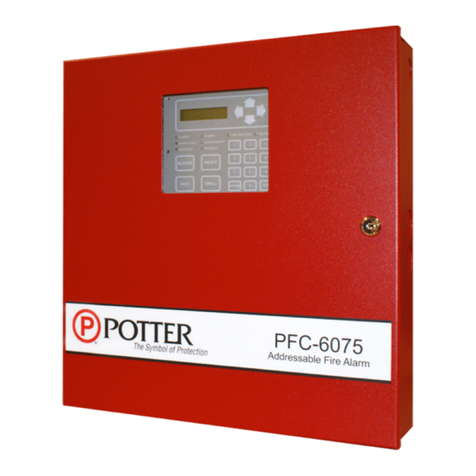
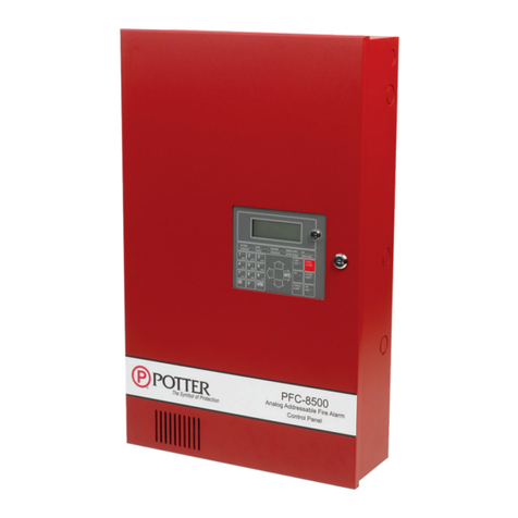
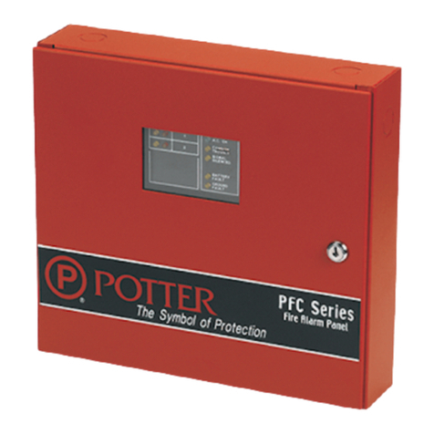
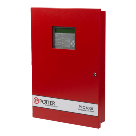
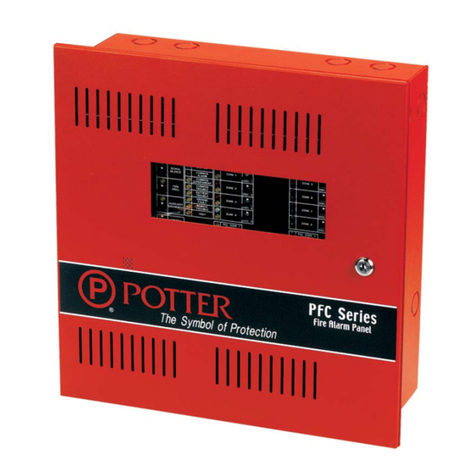
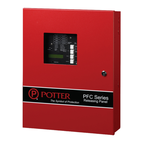
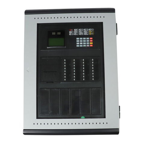
Potter PFC-6006 Owner's manual

PFC-6006 Sprinkler
Monitoring Panel
Installation, Operation & Programming Manual
Manual #5403559–Rev D
11/17
Potter Electric Signal Company, LLC
St. Louis, MO
Customer Service: (866) 240-1870 • Technical Support: (866) 956-1211 • Fax: (314) 595-6999
www.pottersignal.com

2
PFC-6006 • 5403559 • REV D • 11/17
Potter Electric Signal Company, LLC
5757 Phantom Drive Ste 125 • St. Louis, MO 63042 • 314-595-6900 • 800-325-3936
WARRANTY INFORMATION
The essential purpose of any sale or contract for sale of any of the products listed in the POTTER catalog or
price list is the furnishing of that product. It is expressly understood that in furnishing said product, POTTER
does not agree to insure the Purchaser against any losses the Purchaser may incur, even if resulting from the
malfunction of said product.
POTTER warrants that the equipment herein shall conform to said descriptions as to all afrmation of
fact and shall be free from defects of manufacture, labeling and packaging for a period of one (1) or
ve (5) year(s), depending on the product, from the invoice date to the original purchaser, provided that
representative samples are returned to POTTER for inspection. The product warranty period is stated on
the exterior of the product package. Upon a determination by POTTER that a product is not as warranted,
POTTER shall, at its exclusive option, replace or repair said defective product or parts thereof at its own
expense except that Purchaser shall pay all shipping, insurance and similar charges incurred in connection
with the replacement of the defective product or parts thereof. This Warranty is void in the case of abuse,
misuse, abnormal usage, faulty installation or repair by unauthorized persons, or if for any other reason
POTTER determines that said product is not operating properly as a result of causes other than defective
manufacture, labeling or packaging.
The Aforesaid Warranty Is Expressly Made In Lieu Of Any Other Warranties, Expressed Or Implied, It
Being Understood That All Such Other Warranties, Expressed Or Implied, Including The Warranties Of
Merchantability And Fitness For Particular Purpose Are Hereby Expressly Excluded. In No Event Shall
Potter Be Liable To Purchaser For Any Direct, Collateral, Incidental Or Consequential Damages In
Connection With Purchaser’s Use Of Any Of The Products Listed Herein, Or For Any Other Cause Whatsoever
Relating To The Said Products. Neither Potter Nor Its Representatives Shall Be Liable To The Purchaser
Or Anyone Else For Any Liability, Claim, Loss, Damage Or Expense Of Any Kind, Or Direct Collateral,
Incidental Or Consequential Damages Relative To Or Arising From Or Caused Directly Or Indirectly By Said
Products Or The Use Thereof Or Any Deciency, Defect Or Inadequacy Of The Said Products. It Is Expressly
Agreed That Purchaser’s Exclusive Remedy For Any Cause Of Action Relating To The Purchase And/or Use
Of Any Of The Products Listed Herein From Potter Shall Be For Damages, And Potter's Liability For Any And
All Losses Or Damages Resulting From Any Cause Whatsoever, Including Negligence, Or Other Fault, Shall
In No Event Exceed The Purchase Price Of The Product In Respect To Which The Claim Is Made, Or At The
Election Of Potter, The Restoration Or Replacement Or Repair Of Such Product.

3
PFC-6006 • 5403559 • REV D • 11/17
Table of Contents
Section 1: Introduction ............................................................................................................................. 1-1
Purpose of This Manual..........................................................................................................................1-1
System Overview....................................................................................................................................1-1
System Features ......................................................................................................................................1-1
P-Link Accessories............................................................................................................................1-1
How to Use this Manual .........................................................................................................................1-1
Common Terminology ............................................................................................................................1-1
Section 2: Before You Start Installation .................................................................................................. 2-2
System Specications .............................................................................................................................2-2
Environmental Specications .................................................................................................................2-2
Model / Available Cabinet Colors...........................................................................................................2-2
System Congurations / Appliances .......................................................................................................2-2
Electrical Specications..........................................................................................................................2-3
System Size Specications .....................................................................................................................2-3
Main Board Wiring Specications..........................................................................................................2-3
Circuit Separation.............................................................................................................................2-3
Wiring Types......................................................................................................................................2-4
Cabinet Dimensions................................................................................................................................2-5
Cabinet Mounting Instructions ...............................................................................................................2-6
Cabinet Wiring Connections...................................................................................................................2-7
Battery Circuit Calculations....................................................................................................................2-8
Main Supply Circuit................................................................................................................................2-9
Battery Connections................................................................................................................................2-9
Section 3: Installation ............................................................................................................................. 3-10
Input Circuits ........................................................................................................................................3-10
Input Wiring Specications.............................................................................................................3-10
Input Circuit #1 Class A, Style D Wiring Conguration.................................................................3-10
Input Circuits #1-6 Class B, Style B Wiring Conguration ...........................................................3-11
Notication Appliance Circuits Installation..........................................................................................3-12
NAC Wiring Characteristics ...........................................................................................................3-12
NAC Maximum Wiring Impedance Formula ..................................................................................3-12
NAC Wiring Conguration .............................................................................................................3-12
P-Link Points ........................................................................................................................................3-13
Conguration Characteristics ........................................................................................................3-13
Maximum Wire Resistance Formula (Wire Length)........................................................................3-13
P-Link Addresses.............................................................................................................................3-14
Remote Annunciators Installation (RA-6075 or RA-6006)..................................................................3-14
Setting Addresses ............................................................................................................................3-14
DACT Connection ................................................................................................................................3-15
Auxiliary Power....................................................................................................................................3-15
Section 4: Operation ............................................................................................................................... 4-16
Control Panel Basic Operation..............................................................................................................4-16
LCD Display ...................................................................................................................................4-16
Menu Navigation Keys....................................................................................................................4-17
Numeric Keypad..............................................................................................................................4-17
Function Pushbuttons .....................................................................................................................4-17
Status LEDs.....................................................................................................................................4-18
4
PFC-6006 • 5403559 • REV D • 11/17
Canadian Events Display................................................................................................................4-18

Control Panel Menu Tree......................................................................................................................4-20
Section 5: Programming ......................................................................................................................... 5-21
Programming Options............................................................................................................................... 5-21
Programming Overview........................................................................................................................5-23
The Programming Cycle.......................................................................................................................5-23
Software Installation .............................................................................................................................5-23
LEARN Programming ..........................................................................................................................5-24
Connecting the Computer and Panel.....................................................................................................5-24
Transferring Data ..................................................................................................................................5-26
Uploading from Panel to Computer................................................................................................5-27
Downloading Conguration File to Panel ............................................................................................5-28
Enable Remote Access ....................................................................................................................5-28
File New..........................................................................................................................................5-29
File Save / Save As..........................................................................................................................5-29
Audit Errors ....................................................................................................................................5-29
Uploading History Events Status Reports.............................................................................................5-31
History Reports ...............................................................................................................................5-31
Printing Reports..............................................................................................................................5-32
Panel Software Overview .....................................................................................................................5-33
Window Regions / Areas..................................................................................................................5-33
Program Icons.................................................................................................................................5-34
Programming Functions Overview.......................................................................................................5-35
Remote Access Code.............................................................................................................................5-36
User Name / Password....................................................................................................................5-36
General System Functions ....................................................................................................................5-37
Job Details ......................................................................................................................................5-37
General Options..............................................................................................................................5-37
Important Setup Notes: For Canadian Users Only! ......................................................................5-37
Users ...............................................................................................................................................5-38
System E-mail Functions ......................................................................................................................5-39
P-Link E-mail Notication Requirements .......................................................................................5-40
Connecting the Panel to a Network ................................................................................................5-40
E-mail Sent from Panel ...................................................................................................................5-41
E-mail Report Requested from PC..................................................................................................5-42
Receiving E-mail Status Reports.....................................................................................................5-44
Creating E-mail Reminders ............................................................................................................5-45
System Programming............................................................................................................................5-46
Mapping Zones Overview ...............................................................................................................5-46
Single Zones....................................................................................................................................5-46
Multiple Zones ................................................................................................................................5-46
Mapping Terminology .....................................................................................................................5-47
Zone Types / Styles ..........................................................................................................................5-47
Zone Attributes................................................................................................................................5-48
Creating Zones................................................................................................................................5-49
Conguring Zones...........................................................................................................................5-50
Conguring Points..........................................................................................................................5-50

5
PFC-6006 • 5403559 • REV D • 11/17
Input Circuit Functions...................................................................................................................5-51
NAC Functions................................................................................................................................5-52
AUX Functions................................................................................................................................5-52
Adding Points to Zones ...................................................................................................................5-54
Group by Area.................................................................................................................................5-56
Programming Points & Appliances.......................................................................................................5-58
On-Board DACT .............................................................................................................................5-58
Remote Annunciators ......................................................................................................................5-59
Section 6: IP Communication ................................................................................................................ 6-60
IP Reporting Accounts ....................................................................................................................6-61
Section 7: Appendices ............................................................................................................................ 7-63
Appendix A – Basic Operating Instructions..........................................................................................7-63
Appendix B – Modem Connectivity Setup...........................................................................................7-65
Appendix C – System Maintenance and Testing ..................................................................................7-66
Acceptance Test...............................................................................................................................7-66
Periodic Testing and Service...........................................................................................................7-66
Operational Checks ........................................................................................................................7-66
AC Fuse...........................................................................................................................................7-66
Battery Fuse....................................................................................................................................7-66
Battery Maintenance.......................................................................................................................7-66
Replacement and Testing Recommendations ..................................................................................7-67
Proper Handling / First Aid Procedures.........................................................................................7-67
Appendix D – Compatible Points Table ...............................................................................................7-68
Appendix E – Compatible Smoke Detectors Table ..............................................................................7-69
Appendix F – Compatible Auxiliary Circuit Devices...........................................................................7-71
Appendix G – Control Panel Menu ......................................................................................................7-72

6
PFC-6006 • 5403559 • REV D • 11/17
PFC-6006 Sprinkler Monitoring Panel
Installation, Operation & Programming Manual

1-1
PFC-6006 • 5403559 • REV D • 11/17
Section 1: Introduction
The PFC-6006 Sprinkler Monitoring Panel is a compact, simple panel designed to monitor all facets of a wet or dry re sprinkler
system and communicate the status to a monitoring station. The PFC-6006 panel is a listed and approved microprocessor based
sprinkler monitoring panel and complies with UL-864, ULC-S527, ULC-S524, ULC-S537, NFPA-70, and NFPA-72, and NYC
Fire Department Certicate of Approval #6159 & 6184. The panel is provided with six (6) inputs and one 24VDC, 0.5 Amp
Notication Appliance Circuit (NAC) with strobe synchronization. The 2.0 Amp power supply provides ample power to meet
any jurisdictions requirements and will house and charge up to two (2) 18 amp/hour batteries. In addition, the panel has the Potter
P-Link for connection to remote annunciators. The panel has a total 0.5 Amp auxiliary power output for controlling ancillary re
alarm functions.
Purpose of This Manual
This manual is intended to assist in the installation and programming the PFC-6006 Sprinkler Monitoring Panel. Refer to this
manual to properly install and program the PFC-6006. It is recommended that the user follows the procedures as outlined in this
manual to assist in proper installation and prevent damage to the control panel and associated equipment.
System Overview
The PFC-6006 system is designed for use as a sprinkler re control panel for life safety applications.
System Features
The PFC-6006 has six (6) programmable input circuits.
2.0 Amp (24vdc) Power Supply
One (1) Notication Appliance Circuit (NAC) rated at 0.5A maximum.
Power Limited
Built in Sync
Cadence and Temporal Patterns
Programmable as Supervisory
One (1) programmable auxiliary output rated at 0.5 A.
Support for all major synchronization patterns.
Potter/AMSECO®
Gentex®
CooperWheelock®
System Sensor®
Auto Silence and Silence Inhibit.
Built-in Ethernet port for programming and network connectivity.
P-Link RS-485 bus supports system accessories.
Dead-front Cabinet Design
P-Link Accessories
RA-6075 or RA-6006 Remote Annunciator – Maximum of 4 per system
How to Use this Manual
Refer to this manual before contacting Technical Support. The information in this manual is the key to a successful installation
and will assist you in understanding proper wire routing, system requirements, and other guidelines specic to the PFC-6006
system.
Common Terminology
The following table provides you with a list of terms and denitions used with the PFC-6006 system:
Table 1: Terminology
Term Denition
PFC-6006 Cabinet Enclosure
EOLR End of Line Resistor Assembly
Remote Annunicator LCD type Remote Annunicator
NAC Notication Appliance Circuit
P-Link Proprietary RS-485 communication bus
PFC-6006 PCB Board Assembly for complete unit

2-2
PFC-6006 • 5403559 • REV D • 11/17
Section 2: Before You Start Installation
This section addresses information that will help you in completing a successful installation, such as the PFC-6006 cabinet layout,
specications, and environmental considerations.
System Specications
Cabinet Description
yEighteen (18) gauge sheet steel with hinged, removable locked door
yEnclosure dimensions – 18-1/2" x 14-1/4" x 4-3/4"
Visual Indicators
yLCD (2 x 16 alphanumeric character display)
yLED indicators (Red, Green, Amber)
LCD Description
yAlarm, Supervisory and Trouble conditions display applicable condition, status and circuit for each correlating condition
Environmental Specications
yMount indoors only.
yTemperature 32° to 120°F, humidity 93% non-condensing.
yVerify panel is properly grounded.
yRemove all electronic assemblies prior to any drilling, ling, reaming, or punching of the enclosure. When possible, make
all cable entries from the sides, bottom, or rear of the cabinet. Verify that they will not interfere with the batteries or other
components.
yThe panel and system must be tested and maintained in accordance with all local and national codes and ordinances.
yPanel shall be installed so the display is easily readable and the door shall have adequate clearance to access the controls.
Model / Available Cabinet Colors
y3992334 – RED PFC-6006 Sprinkler Monitoring Panel
y3992336 – BLACK PFC-6006 Sprinkler Monitoring Panel
System Congurations / Appliances
Table 2: System Congurations / Appliances
Model Description Local Remote
Station
Central
Station Proprietary
PFC-6006 Main Board/Panel Assembly Y Y Y Y
RA-6006 LCD remote annunciator (cUL) O O O O
RA-6075 LCD remote annunciator (NFPA) O O O O
3005013 End of line resistor assembly Y Y Y Y
Y = Yes, required for applicable section
N = No, not required for applicable section
O = Optional, may or may not be used, has no affect on the applicable section.

2-3
PFC-6006 • 5403559 • REV D • 11/17
Electrical Specications
Please refer to the table below for electrical specications:
Table 3: System Panel Electrical Specications
Panel # NAC Rating per NAC Notes Style and Class
PFC-6006 1 NAC 0.5 Amp Input Circuit 1 may be congured as Class A
or Class B; Inputs 2-6 as Class B only.
Inputs – Class A or B
NAC – Class B
P-Link – Class B
All are Low Voltage and
Power Limited
System Size Specications
Please refer to the table below for system size specications:
Table 4: System Size Specications
Accessories/Subassemblies Maximum System Size
PFC-6006
•y Six (6) input circuits on the main board
•y One (1) notication circuit on the main board
•y One (1) on-board DACT
•y One (1) auxiliary power output*
•y One (1) P-Link connection*
*Note: P-Link 24VDC and auxiliary power combined are not to exceed 0.5A.
Main Board Wiring Specications
There are several wiring requirements to consider before connecting circuits to the main board: (1) the circuit separation,
and (2) wiring types.
All wiring should be sized and installed to comply with NFPA 70, NFPA 72, and local codes and ordinances. For Canadian
installations, all panel wiring should be installed and maintained in accordance with CAN/ULC-S524M, (Standard for all
Installation of Fire Alarm Systems), all other applicable sections of the Canadian Electrical Code and any specic requirements of
the Authority Having Jurisdiction.
Circuit Separation
Proper separation between the different types of circuits must be maintained between Power Limited, Non-Power Limited, and
High Voltage wiring to reduce electrical interferences, transient voltage or voltage ratings.
ySeparations between the different wiring types must be maintained by at least ¼ inch and the wire insulation must be for the
higher voltage.
yThe control panel cabinet has sufcient knockouts located around the periphery allowing the installer to maintain separation
between power limited and non-power limited connections.

2-4
PFC-6006 • 5403559 • REV D • 11/17
Wiring Types
Wiring specications must be followed to prevent damage or other consequences. Please refer to the wiring diagram below for
proper wiring requirements.
Figure 1. PFC-6006 Wire Routing Example
1
2
4
3
Battery leads
2
Power Inputs
1
Route all other wiring away from power input wiring.
3
Run DACT phone lines separately.
4
Wire Routing for PFC-6006
(*Shown with false front removed)
A- A+ B- B+
- +
INPUT2 INPUT3 INPUT4 INPUT5 INPUT6
- + - + - + - +
INPUT1
A B
- +- +- +
Line2 In Line2 Out Line1 In Line1 Out
Tip Ring Tip Ring Tip Ring Tip Ring
PLINKAUXNAC
NOTICE
BATTERY
FUSE
- +
F
U
S
E
DWG #559-12

2-5
PFC-6006 • 5403559 • REV D • 11/17
Refer to table below for a breakout of the different wiring requirements shown by circuit type:
Table 5: Main Board Circuit Wiring Types
Wiring Type
Type of Circuit Voltage Power
AC Connection High Voltage Non-Power Limited
Battery Connection Low Voltage Non-Power Limited
Input Circuits Low Voltage Power Limited
Notication Device Circuit (NAC) Low Voltage Power Limited
P-Link RS-485 Connections Low Voltage Power Limited
Phone Line – DACT High Voltage Non-Power Limited
AUX Power Low Voltage Power Limited
Cabinet Dimensions
Figure 2. PFC-6006 Main Board Module Shown Installed in Cabinet (shown with door removed)
DWG #559-1

2-6
PFC-6006 • 5403559 • REV D • 11/17
Figure 3. PFC-6006 Panel Showing Bezel Dimensions
Cabinet Mounting Instructions
To mount the cabinet:
1. The unit should be mounted in a convenient location, approximately 5 feet from the oor where it will be accessible for
testing and servicing.
2. The main circuit board module should be removed before attempting to mount the cabinet. Disconnect the AC power
from TB5. To remove the module, remove the two screws holding the chassis to the cabinet. Lift the module upwards,
approximately 1/2", in order to clear the cross-beam of the cabinet on which the module rests. Remove the module and set
aside.
3. The PFC unit may be surface mounted or semi-ush mounted using the optional trim bezel (refer to drawings shown earlier
in this section). For semi-ush installations mount the housing so that the front edge protrudes 1" from the nished wall
surface. After all conduits and wiring are in place and the wall surface is completely nished, slide the trim bezel in place and
fasten with 4 #6-32 x 1/4" machine screws and nuts.
4. Install all required conduits, external wiring and points and make all connections that are external to the panel. Replace the
module. With the AC power still turned off at the circuit breaker panel, connect the AC hot, neutral and ground wires to the
terminal block TB5 as shown in the "Cabinet Wiring Connections" drawing shown in this section.
5. Connect all the other wiring to the terminals as shown in the connection drawings. Turn the AC power on and connect the
standby batteries with the cable provided, polarity must be observed.
6. Replace false front panel and secure with mounting screws, taking care to not damage LED annunciator module cable.
7. Verify the operation of the complete system as outlined in the test procedure section.
(4) #6-32 X 1/4”
MACHINE SCREWS
AND NUTS
OPTIONAL TRIM
18 1/2”
14 1/4”
DWG# 3503-8
DWG #559-2

2-7
PFC-6006 • 5403559 • REV D • 11/17
Cabinet Wiring Connections
Figure 4. PFC-6006 Cabinet Wiring
Acknowledgements
Gentex ®, Cooper Wheelock ®, and System Sensor ® synchronization
protocols used with permission. Cooper Wheelock Patent Nos. 5,400,009.
Potter Electric Signal Company LLC
PFC-6006
US: POTAL01BSMP
Complies with 47 CFR Part 68.
Made in USA.
See board for Serial #.
PFC-6006
Sprinkler Monitoring Panel
Primary AC
120VAC, 60Hz, .75 AMP
Min Low AC Detect 98VAC
Battery Charging
All Circuit Impedance Values
27.3VDC @ .5A
Low Battery Detect @20.4VDC
Short Circuit: 0 Ohms
Open Circuit: >10K
Earth Fault to any terminal: 0 Ohms
Main Fuse Specication
1.6A-250VAC
Batt. Fuse Specication
2.5A-250VAC
F.C.C.
CAUTION:
De-Energize Unit Prior to Servicing
Requirements
System must be fully tested after installation.
Intended for indoor use in dry locations only.
Separation of power limited wiring from non-power limited wiring must be at
least 1/4".
Install in accordance with installation manual Part Number 5403559 - ___,
and Operating instructions - Part #5406282 - ___.
NFPA Commercial Protected Premises Control Unit for UL Installations:
See Smoke Detector Compatibility Identifer “A”
SERVICE USE AND COMMERCIAL PROTECTED PREMISES UNIT FOR ULC INSTALLATIONS:
WIRING METHODS SHALL BE IN ACCORDANCE WITH CSA C22.1, SAFETY STANDARD FOR
ELECTRICAL INSTALLATIONS, CANADIAN ELECTRICAL CODE, PART I, SECTIONS 32.
LOCAL SERVICE TYPES (NON-CODED): A, M, SS, WF.
13, 70, and NFPA 72.
Alarm activation requiring activation of two or more automatic detection
devices shall not utilize any time delay.
P/N 5406280-C (10/31/2014)
This device has been veried to comply with FCC Rules Part 15,
Class A Operation is subject to the following conditions:
1. This device may not cause radio interference.
2. This device must accept any interference received including any
that may cause undesired operation.
Battery connection (non-power limited).
Use two (2) 12V batteries connected in series.
Service Use for UL Installations:
- Local
- Remote Station
- Proprietary
- Central Station
E.O.L.E.O.L.
BATTERY
- +
PLINK
A- A+
- + - + - + A B
AUXNAC
Programming
Connection
6 Conventional Inputs, fully programmable
& support 2-wire smoke detector
POTS DACT CONNECTION
ALARM SIGNAL ACTIVATION
PRESS LEFT & RIGHT
ARROW KEYS AT SAME
TIME TO TRIGGER ALARM
SIGNAL ACTIVATION.
LAMP TEST: PRESS [ENTER], [5],
PASSWORD, [6]. PRESS THE [ESC] KEY
WHEN DONE.
GROUND
F
U
S
E
BLACK
WHITE
120VAC 60Hz
Connect to separate
unswitched AC circuit
Use 14 AWG or heavier gauge
wire with 600V insulation
WARNING: RADIO FREQUENCY FROM
TRANSMITTING DEVICES MAY IMPAIR INTENDED
OPERATION OF THE CONTROL UNIT. MAINTAIN
A MINIMUM OF 30 CM BETWEEN TRANSMITTING
DEVICES AND CONTROL UNIT.
AVERTISSEMENT : LES RADIOFRÉQUENCES ÉMISES
PAR LES DISPOSITIFS DE TRANSMISSION
PEUVENT NUIRE AU FONCTIONNEMENT PRÉVU
DU POSTE DE CONTRÔLE. MAINTENIR UNE
DISTANCE D’AU MOINS 30 CM ENTRE LES
DISPOSITIFS DE TRANSMISSION ET LE POSTE DE
CONTRÔLE.
E.O.L.E.O.L.E.O.L.E.O.L.E.O.L.
INPUT3
- + B- B+
INPUT4 INPUT5INPUT6
- + - + - +
INPUT2INPUT1
- +
Line2 In Line2 Out Line1 In Line1 Out
Tip Ring Tip Ring Tip Ring Tip Ring
FUSE
Battery -
Battery +
ONLY DETECTORS THAT ARE SHOWN IN
THE COMPAT IBILITY LIST ARE TO BE USED.
12 3
45 6
78
0ESC
ENTER
POWER ON
EARTH FAULT
ALARM
ALARM SIGNAL ACTIVATION
PRESS LEFT + RIGHT ARROWS
SUPERVISORY
TROUBLESILENCED
FIRE
DRILL
ACK
NOWLEDGE
SIGNAL
SILENCE RESET
9
NYC Fire Dept. Certicate of Approval #6159 & 6184

2-8
PFC-6006 • 5403559 • REV D • 11/17
Battery Circuit Calculations
Before selecting the battery, it is important to determine the minimum size batteries for standby and alarm times desired for each
application. If the wrong batteries are installed in a specic application or incorrect current draw used, the proper standby and
minimum alarm time will not be present.
The battery circuit is rated for 8 to 18 AH batteries and swill operate the panel alarm for at least 24 hours and 5 minutes. The
cabinet will house up to two (2) 8 AH or two (2) 18 AH batteries.
Please use the worksheet shown below to calculate the battery size and current draw required for each application:
Battery Calculation Worksheet
Description Quantity Standby
(mA)
Total
Standby (mA)
Alarm
(mA)
Total
Alarm
(mA)
Main board (PFC-6006) 1 105 160
LCD Remote RA-6075 or RA-6006 20 25
Input Circuit #1
Input Circuit #2
Input Circuit #3
Input Circuit #4
Input Circuit #5
Input Circuit #6
NAC 1
Total (ma) Total (ma)
Convert to Amps x 0.001 Convert to Amps x 0.001
(*Refer to maximum allowable standby current) Total A: Total A:
Multiply by standby hours x____
60 minutes per hour
Alarm time (minutes)
Example:
5 minute alarm: enter 12
÷ ____
Total Standby AH Total Alarm AH
+Total Standby AH
Total AH
Efciency Factor ÷ 0.80
Required AH
*Maximum Allowable Standby Current
(UL 24-Hour standby time)
8 AH .265 A
18 AH .597 A
Important Notes:
1) FACP enclosure can house up to two (2) 18 AH batteries.
2) NFPA 72 requires 24 hours of standby power followed by 5 minutes of alarm activation.
3) Door holder circuits congured to disconnect upon AC loss need not be included in the
battery standby calculation since they will not draw power during that time. Door holders
will contribute to standby current draw when AC is present.
4) Total current must not exceed power supply rating (2A on PFC-6006).
5) LED/Relay current must be accounted for in the battery calculation for the supplying source.

2-9
PFC-6006 • 5403559 • REV D • 11/17
Main Supply Circuit
The AC terminals are located in the upper left hand portion of the main board. The main board supervises the main AC power and
provides indication that the AC power is absent. The terminals are rated at 120 VAC 60 Hertz and are marked so accordingly on
the board.
Figure 5. PFC-6006 AC Terminals
The earth ground connection is marked as “ " and is the furthest connection from the line voltage connection.
The AC input power rating is: Maximum of .75A at the nominal 120 VAC rating.
Battery Connections
The battery charging circuit is located on the main panel in the lower left portion of the board. The maximum battery charging
current is .5 amp DC; the charging voltage is approximately 27.3 VDC and is supervised.
Note: The battery should be clearly labeled as “Sealed Lead Acid Battery” or equivalent UL listed or UL Recognized.
Connect the battery wire leads to the terminal connections, as shown. Batteries should be replaced every ve (5) years or sooner
depending on annual testing.
Figure 6. PFC-6006 Battery Connections
Panel
Connections
BATTERY
-+
12 V
Battery
-+
12 V
Battery
-+
DWG #559-10
LN
AC120V/AC230V,50 /60Hz
AC POWER
Black
White
Ground
120
VAC 60 Hz
Connec
t to separate
Un
switched AC circuit
Use 14 AWg wire or Heavier
with 600V Insulation

3-10
PFC-6006 • 5403559 • REV D • 11/17
Section 3: Installation
This section addresses installation procedures for Input Circuits 1–6, the NAC, the on-board DACT, and the optional RA-6075
or RA-6006 Remote Annunciator. Wiring requirements and conguration examples are included throughout this section. Please
read this section carefully before installing points and accessories to ensure proper installation.
Input Circuits
There are six (6) programmable Input or Initiating Device Circuits (IDC) provided on the PFC-6006, which are the same as
a conventional re system input. They are supervised, and power limited to protect 2-wire smoke detectors. Input Circuit #1
may be wired for either Class A, Style D or Class B, Style B; whereas Inputs #2-6 may be Class B, Style B only. All inputs are
suitable for automatic, manual, waterow or sprinkler supervisory service. (Please refer to the wiring examples located in this
section.)
Note: The panel has the intelligence to determine the applicable style for Input Circuit #1 based on the wiring
conguration used.
Input Wiring Specications
yMaximum short circuit current = 32mA.
yMaximum wiring resistance = 100 Ohms.
yMaximum wiring capacitance = 1 mF.
yMaximum wire length in feet = 100/Ohms per 1 ft. of wire.
yNormal standby current = 2.5 mA.
yOperating voltage range = 15.1VDC - 25.4VDC.
Input Circuit #1 Class A, Style D Wiring Conguration
Figure 7. Example of Input 1, Class A, Style D
Notes:
1. Input Circuit #1 may be wired as either Class A or Class B.
2. All other inputs are Class B only.
3. Maximum wiring resistance must not exceed 100 ohms.
4. The input has ground fault detection with 0 ohm impedance to ground.
5. The Potter part number for the listed end of line assembly is #3005013 EOL Resistor Assembly.
L N G
BATTERY
- +
NAC
- +
AUX
+-
P-LINK
+- BA
ETHERNET INPUT 1
A- A+ B- -
B+ -+ -+ -+ -+ +
INPUT 2 INPUT 3 INPUT 4 INPUT 5 INPUT 6
TIP RING TIP RING TIP RING TIP RING
LINE 2 OUTLINE 2 IN LINE 1 OUTLINE 1 IN
WATERFLOW SWITCH
NORMALLY OPEN CONTACTS
CLASS A WIRING
PFC-6006
Input Circuit #1
Terminal Connection
DWG #559-4

3-11
PFC-6006 • 5403559 • REV D • 11/17
Input Circuits #1-6 Class B, Style B Wiring Conguration
Figure 8. Example of Inputs Wired as Class B, Style B
Notes:
1. Maximum wiring resistance must not exceed 100 ohms.
2. The input has ground fault detection with 0 ohm impedance to ground.
3. The Potter part number for the listed end of line assembly is #3005013 EOL Resistor Asssembly.
L N G
BATTERY
- +
NAC
- +
AUX
+-
P-LINK
+- BA
ETHERNET INPUT 1
A- A+ B- -
B+ -+ -+ -+ -+ +
INPUT 2 INPUT 3 INPUT 4 INPUT 5 INPUT 6
TIP RING TIP RING TIP RING TIP RING
LINE 2 OUTLINE 2 IN LINE 1 OUTLINE 1 IN
COMM NO NC
COMM NO NC
5.1K EOL
SPRINKLER VALVE TAMPER SWITCH
NORMALLY OPEN CONTACTS
CLASS B WIRING
DWG #559-5
PFC-6006
Input Circuits #1-6
Terminal Connection

3-12
PFC-6006 • 5403559 • REV D • 11/17
Notication Appliance Circuits Installation
There is one (1) NAC circuit provided on the PFC-6006 rated as continuous 0.5 amps at 24 VDC. The NAC circuit is congurable
as Class B, Style Y only. (Please refer to the wiring example located in this section.)
NAC Wiring Characteristics
yOutput is supervised and regulated.
yCircuit is power limited.
yNormal standby supervisory current is approximately 1.2 mA
yLow current trouble activation is 0.8 mA; High current trouble activation is 1.7 mA.
yMaximum RMS current is .5A.
Note: Type of NAC output is selectable, and may be congured for strobe synchronization with Potter/AMSECO®, Cooper
Wheelock®, Gentex®, or System Sensor® strobe points. Refer to the listing of compatible models located in the “NAC
Compatibility Document”, Potter #5403592, for this information.
NAC Maximum Wiring Impedance Formula
The maximum impedance is a function of the load placed on the circuit. To calculate the maximum line current impedance, use
the following formula:
(Alarm Current of Notication Appliance) x (Wire Resistance) < 1.2 Volts
NAC Wiring Conguration
Figure 9. NAC Class B, Style Y Wiring Example
Notes:
1. The Potter part number for the listed end of line assembly is #3005013 EOL Resistor Assembly.
2. The panel has ground fault detection on the NAC circuit. The impedance to ground for ground fault detection is 0 ohms.
3. The 1.2 Volts is based on the worst case loading at the remote end of the NAC circuit (lump sum method). The total drop
of 1.2 Volts should be measured from the terminals to the most remote device.
DWG #559-6A
NAC
- +
Notification Appliances
5.1k EOL
Potter Part # 3005013
Note: the resistance of external wiring shall be determined using the following formula ---
(Alarm Current of Notification Appliance) x (Wire Resistance) < 1.2 Volts

3-13
PFC-6006 • 5403559 • REV D • 11/17
P-Link Points
Accessory points, such as the RA-6075 or RA-6006 remote annunciator, are connected to the main control panel utilizing the
four-wire P-Link bus for power and communication. This panel supports a maximum of four (4) P-Link points, which can be
connected using a Class B, Style 4 wiring style.
Conguration Characteristics
yP-Link current rating may not exceed 0.5 amp based on the total between auxiliary and P-Link.
yP-Link maximum current is 500 mA.
yP-Link voltage rating is 24 VDC.
• Continuous DC frequency.
• P-Link circuit is supervised and power-limited.
Maximum Wire Resistance Formula (Wire Length)
The maximum resistance is based on the load placed on the circuit. To calculate the maximum wire resistance, use the following
formula:
(Total Annunciator Alarm Current) x (Wire Resistance) < 6 Volts
Figure 10. P-Link Device Class B Wiring Example
To the next device
- + A B
Expansion
Device
- + A B
P-LINK
- + A B
Panel
Connection
Expansion
Device
DWG #602-11A

3-14
PFC-6006 • 5403559 • REV D • 11/17
P-Link Addresses
Every P-Link device has a ve position dip switch which is used to program the device address ranging from one (1) to thirty-one
(31). Use the chart below to reference Dip Switch Settings:
Remote Annunciators Installation (RA-6075 or RA-6006)
Up to four (4) annunciators may be connected to the main sprinkler monitoring panel. The RA-6075 or RA-6006 provides a
2 x 16 character LCD display, along with standard function and numeric keys. It is listed and designed be mounted on a at non-
condensing surface or electrical box.
Setting Addresses
An annunciator's address is set by dip switch S1, which is located on the back of the annunciator. The address must be set
in the range of one to thirty-one (1–31) to be recognized by the panel. (Refer to chart shown above for P-Link DIP switch
programming.)
Figure 11. Annunciator Back Panel View
Annunciator
Address
Dip Switch Settings
SW-1 SW-2 SW-3 SW-4 SW-5
1 On Off Off Off Off
2Off On Off Off Off
3 On On Off Off Off
4Off Off On Off Off
5 On Off On Off Off
6Off On On Off Off
7 On On On Off Off
8Off Off Off On Off
9 On Off Off On Off
10 Off On Off On Off
11 On On Off On Off
12 Off Off On On Off
13 On Off On On Off
14 Off On On On Off
15 On On On On Off
16 Off Off Off Off On
Annunciator
Address
Dip Switch Settings
SW-1 SW-2 SW-3 SW-4 SW-5
17 On Off Off Off On
18 Off On Off Off On
19 On On Off Off On
20 Off Off On Off On
21 On Off On Off On
22 Off On On Off On
23 On On On Off On
24 Off Off Off On On
25 On Off Off On On
26 Off On Off On On
27 On On Off On On
28 Off Off On On On
29 On Off On On On
30 Off On On On On
31 On On On On On
DIP SWITCH
A
B
+
-
DWG #593-31
Other manuals for PFC-6006
1
This manual suits for next models
2
Table of contents
Other Potter Control Panel manuals

Potter
Potter PFC-3002T User manual

Potter
Potter PFC-6200 User manual

Potter
Potter PFC-3005T User manual

Potter
Potter PFC-8000 Series User manual

Potter
Potter PFC-100RC User manual

Potter
Potter PFC 2000RC User manual

Potter
Potter PFC-5000 Series User manual

Potter
Potter PFC-6075R Owner's manual

Potter
Potter PFC-6075 Owner's manual

Potter
Potter PFC-4410RC Instruction Manual