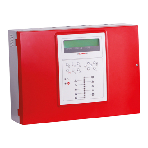
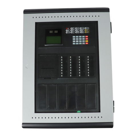
Potter PFC-4064 Operating instructions

PFC-4064
Conventional Fire Alarm Panel
Keypad Programming Guide
Manual #8870080–Rev A
12/17
Potter Electric Signal Company, LLC
St. Louis, MO
Customer Service: (866) 240-1870 • Technical Support: (866) 956-1211 • Fax: (314) 595-6999
www.pottersignal.com

PFC-4064 KEYPAD PROGRAMMING • 8870080 • REV A • 12/17
Potter Electric Signal Company, LLC
5757 Phantom Drive Ste 125 • St. Louis, MO 63042 • 314-595-6900 • 800-325-3936
WARRANTY INFORMATION
The essential purpose of any sale or contract for sale of any of the products listed in the POTTER catalog or
price list is the furnishing of that product. It is expressly understood that in furnishing said product, POTTER
does not agree to insure the Purchaser against any losses the Purchaser may incur, even if resulting from the
malfunction of said product.
POTTER warrants that the equipment herein shall conform to said descriptions as to all afrmation of
fact and shall be free from defects of manufacture, labeling and packaging for a period of one (1) or
ve (5) year(s), depending on the product, from the invoice date to the original purchaser, provided that
representative samples are returned to POTTER for inspection. The product warranty period is stated on
the exterior of the product package. Upon a determination by POTTER that a product is not as warranted,
POTTER shall, at its exclusive option, replace or repair said defective product or parts thereof at its own
expense except that Purchaser shall pay all shipping, insurance and similar charges incurred in connection
with the replacement of the defective product or parts thereof. This Warranty is void in the case of abuse,
misuse, abnormal usage, faulty installation or repair by unauthorized persons, or if for any other reason
POTTER determines that said product is not operating properly as a result of causes other than defective
manufacture, labeling or packaging.
The Aforesaid Warranty Is Expressly Made In Lieu Of Any Other Warranties, Expressed Or Implied, It
Being Understood That All Such Other Warranties, Expressed Or Implied, Including The Warranties Of
Merchantability And Fitness For Particular Purpose Are Hereby Expressly Excluded. In No Event Shall
Potter Be Liable To Purchaser For Any Direct, Collateral, Incidental Or Consequential Damages In
Connection With Purchaser’s Use Of Any Of The Products Listed Herein, Or For Any Other Cause Whatsoever
Relating To The Said Products. Neither Potter Nor Its Representatives Shall Be Liable To The Purchaser
Or Anyone Else For Any Liability, Claim, Loss, Damage Or Expense Of Any Kind, Or Direct Collateral,
Incidental Or Consequential Damages Relative To Or Arising From Or Caused Directly Or Indirectly By Said
Products Or The Use Thereof Or Any Deciency, Defect Or Inadequacy Of The Said Products. It Is Expressly
Agreed That Purchaser’s Exclusive Remedy For Any Cause Of Action Relating To The Purchase And/or Use
Of Any Of The Products Listed Herein From Potter Shall Be For Damages, And Potter's Liability For Any And
All Losses Or Damages Resulting From Any Cause Whatsoever, Including Negligence, Or Other Fault, Shall
In No Event Exceed The Purchase Price Of The Product In Respect To Which The Claim Is Made, Or At The
Election Of Potter, The Restoration Or Replacement Or Repair Of Such Product.
ii
PFC-4064 KEYPAD PROGRAMMING • 8870080 • REV A • 12/17
iii
Table of Contents
Section 1: Introduction ..............................................................................................................................1
Section 2: Pre-Programming Procedures and Defaults ..........................................................................2
Section 3: Operation ..................................................................................................................................4
Section 4: Programming Options .............................................................................................................6
Section 5: Manual Programming Overview ............................................................................................9
The Programming Cycle............................................................................................................................ 9
System Setup: Software Zone Attributes ................................................................................................... 9
System Setup: Points................................................................................................................................ 10
System Setup: Assign Zones.................................................................................................................... 12
LEARN Programming ............................................................................................................................. 14
Section 6: DACT Programming ..............................................................................................................15
Section 7: Panel Menu Trees ...................................................................................................................18

PFC-4064 KEYPAD PROGRAMMING • 8870080 • REV A • 12/17
THIS PAGE INTENTIONALLY LEFT BLANK
iv

PFC-4064 KEYPAD PROGRAMMING • 8870080 • REV A • 12/17
Section 1: Introduction
The PFC-4064 Conventional Fire Panel is a compact, expandable panel designed to monitor all facets of a re alarm system
and communicate the status to a monitoring station. The PFC-4064 panel is a listed and approved microprocessor based
conventional re panel and complies with UL-864, NFPA-70, and NFPA-72.
Purpose Of This Manual
This manual is intended to assist in the programming of the PFC-4064 Conventional Fire Panel via its keypad. Refer to this
manual to properly program the PFC-4064. It is recommended that the user follows the procedures as outlined in this manual
to assist in proper programming and prevent damage to the control panel and associated equipment.
System Overview
The PFC-4064 system is designed for use as a re control panel for life safety applications.
System Features
The PFC-4064 has six (6) programmable input circuits, and is expandable to 192 using thirty-one (31) IDC-6 cards, each
providing six (6) additional programmable input circuits.
Four (4) Notication Appliance Circuits (NAC) rated at 3.0A maximum
Power Limited
Built in Sync
Cadence and Temporal Patterns
Programmable to activate on a Supervisory condition
Support for all major strobe synchronization patterns.
Gentex®
AMSECO®
Wheelock®
System Sensor®
Auto Silence and Silence Inhibit.
Built-in Ethernet port for programming and network connectivity.
Built-in Email support to communicate system status and event information.
Customizable Reminder Emails.
4,000 event non-volatile history buffer
99 Software Zones
4 X 20 character LCD display
Built-in IP Reporting
How To Use This Manual
Refer to this manual before contacting Technical Support. The information in this manual is the key to a successful
programming and will assist you in understanding proper system start up, device designation, and other guidelines specic to
the PFC-4064 system.
1

PFC-4064 KEYPAD PROGRAMMING • 8870080 • REV A • 12/17
Section 2: Pre-Programming Procedures and Defaults
Before beginning PFC-4064 programming, install the panel following the directions included in the PFC-4064 Installation
and Operations Manual (Potter document # 5403638). Failure to properly install and wire the physical panel and any devices/
accessories being used in conjunction with it can result in system errors and difculty in programming, as well as potentially
damaging the re alarm system.
System Defaults: Input Circuit
The PFC-4064 has a total of 6 built-in input circuits available for use. These inputs are for monitoring devices such as smoke
detectors, pull stations and waterow switches. The terminals for input devices (shown below) are located at the top right
corner of the control panel’s circuit board. Each circuit has a factory default setting that can be used to connect to a specic
type of input device for ease of installation and programming.
System Defaults: Output Circuit
The PFC-4064 has a total of 4 built-in output notication appliance circuits (NACs) available for use. These outputs are for
notication devices, The output NAC terminals (shown below) are located at the bottom right corner of the control panel’s
circuit board. Each circuit has a factory default setting that can be used to connect to a specic type of output device for ease
of installation and programming.
Input Terminal Default Settings
Terminal # Setting Type
1Waterow
2Smoke
3Pull Station
4General Fire Alarm
5 General Fire Alarm
6Non-latching
Tamper Supervisory
NAC Output Terminal Default Settings
Terminal # Activation Setting Type
1Waterow Only
2Any Alarm
3Any Alarm
4Any Alarm
2

PFC-4064 KEYPAD PROGRAMMING • 8870080 • REV A • 12/17
System Defaults: Relay Circuit
The PFC-4064 has a total of 4 built-in relays available for use. The relays (shown below) are located along the central bottom
edge of the control panel’s circuit board.
Relay Output Terminal Default Settings
Terminal # Activation Setting Type
1 Alarm
2 Supervisory
3 Waterow
4Trouble
3

PFC-4064 KEYPAD PROGRAMMING • 8870080 • REV A • 12/17
Section 3: Operation
This section provides an overview of the control panel’s basic operations, which includes the status LEDs, function
pushbuttons, and a Control Panel Menu Tree quick reference sheet.
Control Panel Basic Operation
The control panel is comprised of a four (4) line x 20-character LCD display panel, arrow keys, push button function keys,
status LEDS, and the numeric keypad. A description of each component is included in this section; please refer to the gure
shown below.
Figure 1. PFC-4064 Control Panel Display
Note: Authorized system operators must use a key to open the outer door of the cabinet.
LCD Display
The LCD panel displays the standard Start-up menu as shown below. The LCD displays up to eighty (80) characters of
information displays, providing important feedback to system users, i.e., system messages, status information, trouble
conditions, or input changes. The LCD also provides access to the Main Menu for daily system operations and specic
programming functions.
Figure 2. LCD Start-Up Screen
Note: You may customize the Start-up screen to display a specic job site name or other relevant descriptive text by
selecting ‘Panel Name’ in the System Setup submenu.
SILENCE
POWER
EARTH FAULT
SILENCED ALARM
SUPERVISORY
TROUBLE
RESET
ACK DRILL
1 2 3
4 5 6
7 8 9
0ESCENTER
Status
LEDs
Numeric Keypad
Arrow Keys
LCD Display
Function
Pushbuttons
PFC-4064
All Systems Normal
11/16 21:20:00
PFC-4064
All Systems Normal
11/16 21:20:00
System Setup
1=Panel Name
2=Idle Message
3=Display Option
4

PFC-4064 KEYPAD PROGRAMMING • 8870080 • REV A • 12/17
Menu Navigation Keys
The arrow keys allow you to scroll or move through the control panel menus. The Enter and Esc keys may also be used
to navigate through menus; they are located on the numeric keypad. The table shown below provides a summary of the
navigation keys.
Table 1: Menu Navigation Keys
Push button Description
Moves/scrolls up or down through menus, select numbers and letters where appropriate.
Scrolls to the left or right to display details, if any, of current menu item, select numbers and letters where
appropriate.
Note: When the LCD panel displays a LEFT and/or RIGHT arrow, this indicates more information may be viewed.
Displays the Main Menu or selects the current menu option.
Note: The blinking “” indicates the current menu option.
Returns to previous menu or backs up to previous screen.
Numeric Keypad
The numeric keypad allows you to enter user codes when required to access restricted functions. Alternatively, the numbers
may be used to quickly select menu options vs. using the arrow and Enter keys to select a function.
Figure 3. Control Panel Numeric Keypad
Function Pushbuttons
The four (4) function pushbuttons are used when system alarm / trouble conditions occur or to perform a re drill. Refer to
the table below for a brief summary of the pushbuttons:
Table 2: Control Panel Pushbuttons
Pushbutton Description
Press to acknowledge the currently displayed condition.
Press to silence all outputs programmed as silenceable and buzzer.
Press to reset panel to normal condition.
Press to begin a re drill.
5

PFC-4064 KEYPAD PROGRAMMING • 8870080 • REV A • 12/17
Section 4: Programming Options
The control panel is congured using the built in keypad. The panel stores the site specic conguration data in
non-volatile memory.
NOTICE TO USERS, INSTALLERS, AUTHORITIES HAVING JURISDICTION, AND OTHER INVOLVED PARTIES
This product incorporates eld-programmable software. In order for the product to comply with the requirements in the Standard for Control Units and
Accessories for Fire Alarm Systems, UL 864, certain programming features or options must be limited to specic values or not used at all as indicated below.
Topic Feature or
Option
Permitted
in UL
(Y/N)
Possible Settings Setting(s)
Permitted
in UL864?
Comment
Misc Idle LCD Message Y Yes/No All Settings Allowed
Misc Display Events Y Initial Event
Newest Event
Initial Event Auto display of
rst event
Misc SLC Blink Y Normal/Slow/Off All Settings Allowed
Misc Alarm Verication
Time
Y0-60 Sec All Settings Allowed
Misc Waterow Delay Y 0-255 Sec All Settings Allowed
Misc AC Report Delay Y 30 Minutes to 30 Hours 1-3 Hours For UL864 use
1-3 Hr
Misc DH Low AC
Dropout Delay
Y No delay, 15 Sec, 1 minute,
5 minute
All Settings Allowed
Misc Autotest Time Y Time of Day All Settings Allowed
Misc Autotest Interval Y 1-24 Hours All Settings Allowed
Misc Strobes Active
When Silenced
Y Yes/No All Settings Allowed
Misc 50 Hz AC Y Yes/No All Settings Allowed
Misc CO Tone on
Annunciators
Y Yes/No All Settings Allowed
Misc Low Temp Events
Are Supervised
Y Yes/No All Settings Allowed
Misc Disable 24 hours
PZT Resound
Y Yes/No No
Misc Display AM/PM Y AM/PM, 24 Hour All Settings Allowed
Misc Synchronize to
Network Time
Y Yes/No All Settings Allowed
Misc SNTP Server Y North-America.Pool.NTP.
org
All Settings Allowed
Misc Time Zone Y 24 Time Zone Selections All Settings Allowed
Misc DST Enabled Y Yes/No All Settings Allowed
Misc DST Start Y Month/Day All Settings Allowed
Misc DST End Y Month/Day All Settings Allowed
6

PFC-4064 KEYPAD PROGRAMMING • 8870080 • REV A • 12/17
Topic Feature or
Option
Permitted
in UL
(Y/N)
Possible Settings Setting(s)
Permitted
in UL864?
Comment
Zone Zone Style Y Alarm
Supervisory
PAS
Auxiliary
Fire Drill
Waterow
System Alarm
System Supervisory
System Trouble
CO Alarm
CO Supervisory
All Settings Allowed
Zone Alarm Count Y1-10 All Settings Allowed
Zone Silenceable Y Yes/No All Settings Allowed
Zone Silence Inhibit Y Yes/No All Settings Allowed
Zone Auto Silence Y Yes/No All Settings Allowed
Zone Auto Unsilence Y Yes/No All Settings Allowed
Zone Restore Delay Y 0-300 Sec Full range allowed
Zone Latching Y Yes/No All Settings Allowed
Zone Local Y Yes/No All Settings Allowed
Zone Output Pattern YConstant
ANSI Temp 3
March Code
Double Time
ANSI Temp 4
All Settings Allowed
IDC-6 Dry Contact Input
Functions
YPull Station
Water Flow
Supervisory
Tamper
Fire Drill
Trouble Monitor
Aux
Abort
Release Follower
Reset
Silence
Fire Alarm
Disable Inputs
Disable Outputs
Disable Inputs and Outputs
Lamp Test
CO Alarm
CO Supervisory
HVAC Reset
All Settings Allowed
Exception: Disabled
functions allowed when
used with a keyed
switch.
Applies to all
dry-contact input
devices & circuits
7

PFC-4064 KEYPAD PROGRAMMING • 8870080 • REV A • 12/17
Topic Feature or
Option
Permitted
in UL
(Y/N)
Possible Settings Setting(s)
Permitted
in UL864?
Comment
NACs Function Y General Purpose
AMSECO Sync
Gentex Sync
Gentex Sync with T4
System Sensor Sync
Wheelock Sync
Constant Output
Resettable Output
Door Holder Output
ANSII Output
City Tie Output
All Settings Allowed
Except: A Supervisory
event cannot trigger a
T4 NAC.
Species use of
NAC circuit(s)
AUX PWR Function Y Constant Output
Resettable Output
Door Holder Output
ANSII Output
All Settings Allowed
DACT Daily Test Call Y Any time of day All Settings Allowed Alternates between
line 1 and 2 if
line 2 is enabled.
E-Mail Email Status
Reports
NAlarms, Troubles,
Supervisory, Test, History
& Status Reports
IP-Reporting IP Based Central
Station Reporting
YAlarm, Supervisory,
Trouble & Test Reports
All Settings Allowed
On-Board
Programmable
Relays
Function Y Alarm, Supervisory,
Trouble, Low AC &
Waterow
All Settings Allowed Species use of
programmable
relays 1-4
8

PFC-4064 KEYPAD PROGRAMMING • 8870080 • REV A • 12/17
9
Section 5: Manual Programming Overview
The panel can be programmed using either the keypad or Potter’s panel programming software.
The Programming Cycle
The following is the recommended approach to program the FACP via the panel’s keypad. Active selections are indicated in
Italics in this manual, while the panel will indicate an active selection with a small ashing arrow on the screen where the “=”
symbol is. The “Enter” button is used to access a menu and save any changes.
System Setup: Software Zone Attributes
To begin setting up zones and points on the PFC-4064 system, press “Enter” on the keypad to bring up the Main Menu. Scroll
down to Programming using the arrow keys, or press “6”. NOTE: Full menu trees are shown in Section 5
You will be prompted to enter an access code. The default code is 1111, which can be changed under “8 = User Codes” in
the System Setup submenu at a later date for security purposes. When the code is entered, the PFC 4064 will automatically
take you to the Programming sub menu shown below.
Once inside the programming options, select “System Setup”, then press “Enter” to bring up the System Setup sub menu
shown below, then select “Zones”. This is where software zones are congured. In latter steps, input circuits and output
circuits (NACs) are assigned to these software zones. The attributes assigned to these zones will inuence how the circuits
operate. Options include; Alarm or Supervisory zone styles ,silenceable or non-silenceable signaling devices, latching or non
latching, etc.
Once inside the Zones sub menu, you can edit each zone’s (in order) style, name, count, latching, local zone, output pattern,
auto silence/unsilence, silence inhibit time, restore delay, relay activate delay. A full name of the selected eld will alternate
between itself and “Press ENTER to edit” at the bottom of the screen. Use the right arrow button to access all the available
options.
Main Menu
4=Walk Test
5=System Tools
6=Programming
Programming
1=System Setup
2=Learn Menu
3=Panel Default
System Setup
1=Zones
2=Points
3=Assign Zones
# Name Style Count
1Zone Alarm 1
2 Zone Alarm 2
Press ENTER to edit
# Silnc Latch Local
1 No No n/a
2 No No n/a
Press ENTER to edit

PFC-4064 KEYPAD PROGRAMMING • 8870080 • REV A • 12/17
10
To edit/rename an entry, select the eld you would like to change using the arrow keys. Press “Enter” to open the eld,
which should display (example shown below) with the rst character blinking. Once the eld is available, scroll through the
available characters to nd the letter, number, or special character desired using the Up/Down arrow keys. Move to the next
character space using the left/right arrow keys. When nished, press “Enter” to save changes.
Note: When selecting the order the zones are listed in, the screen will allow you to change the number through either the up/
down arrow keys or by manually typing in the order number preferred. All single digit number selections must use a zero. It
is highly recommended that the assigned zone name and number is written down to avoid confusion and programming errors.
System Setup: Points
Once the software zones are established, the next step is to congure the input circuits and NAC circuits (Points) of the
re alarm system. Points are input or output signal devices, with the functions and description of both being set here. The
on-board output NAC & Aux Power circuits will be found under Built-In Power Supply while the on-board input zones are
located under Built-In IDC6
It is recommended to do this immediately after setting up the Zones.
Within the Programming submenu, select System Setup, then select Points.
You will then have a choice between setting up points for the Built-in Power Supply (used for NAC output devices such
as horns, strobes, door holders, etc) or the Built-in IDC6 (used for input devices such as smoke detectors, pull stations,
owswitches, etc.). Use the right arrow button to access all the available options.
System Setup
1=Zones
2=Points
3=Assign Zones
Select:
Built-in PWR Sup
Built-in IDC6
Zone Name
Zone 1
# Name Funct Suprv
1 Conv Smoke 1
2 Conv Smoke 2
Press ENTER to edit
Select Zone:
Current: 1
Set: [01]
# Suprv AlVer EOL
1 No No n/a
2 No No n/a
Press ENTER to edit

PFC-4064 KEYPAD PROGRAMMING • 8870080 • REV A • 12/17
11
To edit/rename an entry, select the eld you would like to change using the arrow keys as done when setting up the software
zones. Press “Enter” to open the eld. Once the eld is available, scroll through the available characters to nd the letter,
number, or special character desired using the Up/Down arrow keys. Move to the next character space using the left/right
arrow keys. When nished, press “Enter” to save changes before pressing “ESC”.
When selecting the order the points are listed in, the screen will allow you to change the number through either the up/down
arrow keys or by manually typing in the order number preferred. All single digit number selections must use a zero. It is
highly recommended that the assigned point name and number is written down to avoid confusion and programming errors.
When selecting a Point Function, use the up/down arrow keys to select a function for the notication or signaling circuit.
The options for the output (NAC) circuits are:
• City Tie
• Aux Door Holder Low AC (Aux D-Hold-AC)
• Aux Door Holder (Aux D-Hold)
• Aux Resettable
• Aux Constant
• Wheelock Sync
• System Sensor Sync (Sys Sensor)
• Gentex Sync w/T4
• Gentex Sync
• AMSECO Sync
• NAC Gen Purp
• Unused
Zone Name
NAC 1
Select Point:
Current: 1
Set: [1]
NAC 1
Point Function
Curr: NAC Gen Purp
Set: [City Tie ]
The options for the input circuits are:
• Smoke
• HVAC Restart
• Supervisory
• CO Alarm
• Lamp Test
• Disable Inputs/Outputs
• Disable Outputs
• Disable Inputs
• Fire Alarm
• Silence
• Reset
• Aux Input
• Trouble Monitor
• Fire Drill
• Tamper
• Waterow
• Pull Station
• Heat
• Unused

PFC-4064 KEYPAD PROGRAMMING • 8870080 • REV A • 12/17
12
System Setup: Assign Zones
Once the input and output points have been set, they will need to be assigned to an appropriate zone. Zones are where input
and output device correlations are established. An Input Circuit will activate an output circuit (NAC) when they are assigned
to the same zone. Circuits that initiate an Alarm are assigned to Alarm Style Zones. Circuits that initiate a Supervisory signal
must be assigned to a supervisory style zone.
Within the Programming submenu, select System Setup, then select Assign Zones.
When inside the Zone Assignment submenu, you’ll have the option to add or delete points to the software zones you
established earlier.
Select “Add to Zone” or “Delete From Zone” to bring up the selection screen. The options are through the Power Supply and
IDC6, which contain the respective points you programmed into each earlier.
Scroll through the available points previously assigned by using the up/down arrow keys. Select the point being assigned or
deleted by pressing “Enter”.
You will see one of the following two screens displayed as shown below depending on whether the point is being added
or deleted. Use the up/down arrow keys to scroll through the available choices, then press “Enter” when the zone number
desired has been reached and highlighted by the ashing arrow. You will receive a message on the screen stating “Point has
been added /deleted” if done correctly.
Note: If a point has already been assigned to the zone selected, you will receive a message stating so.
Zone Assignment
1=Add to Zone
2=Del From Zone
ESC=Exit
Select:
Built-in PWR Sup
Built-in IDC6
Select:
NAC 1
NAC 2
NAC 3
Select Zones:
Zone 1
Zone 2
Zone 3
Del from Zone [001]
System Setup
1=Zones
2=Points
3=Assign Zones

PFC-4064 KEYPAD PROGRAMMING • 8870080 • REV A • 12/17
13
System Setup: Program Relays
The relays are congured to activate on a specic panel condition (Alarm, Trouble, Supervisory and Waterow). The relay
default settings are detailed in Section 2.
To change the defaults, go to the Programming submenu, enter the four digit access code when prompted, then go to the
System Setup submenu, and select “Program Relays”.
Once inside the Program Relays submenu, select the relay being changed from the four options available.
The screen will show the currently selected relay’s function. To change the function, use the up/down arrow keys. Press
“Enter” to select and save the new function.
Main Menu
4=Walk Test
5=System Tools
6=Programming
Programming
1=System Setup
2=Learn Menu
3=Panel Default
System Setup
3=Assign Zones
4=Program Relays
5=P-Link Devices
Select. Prog. Relay
1=Prog. Relay 1
2=Prog. Relay 2
3=Prog. Relay 3
Relay Function
Curr: Alarm
Set: [Waterow ]
Point is already assigned
to this zone.

PFC-4064 KEYPAD PROGRAMMING • 8870080 • REV A • 12/17
14
LEARN Programming
The LEARN function is available through the control panel, and is an efcient way to add the UD-1000 DACT and other
accessory cards wired to the P-Link circuit. LEARN detects all connected devices, assigns a name and selects the applicable
device type
To run the LEARN mode:
1. From the control panel, press the Enter button to display the Main Menu.
• Press 6 to select Programming. The “Enter Code” prompt displays.
• Enter the user code when prompted. Factory default code is 1111.
• Press 2to select LEARN. Press 1to select LEARN ALL. System begins searching for devices.
2. Results are grouped by device type. If no changes are detected, the prompt “No changes” displays.
• Use down arrow to scroll through results by device type: It is recommended that the assigned number of each
point is written down at this time.
Note: The abbreviation “Pts” refers to addressable input and output points.
• Select Esc when nished reviewing results. The system prompts to save or discard le.
3. Press 1to Accept changes; press 2 to Cancel changes.
• When user presses ‘1’ to accept changes, user will need to press the ESC button to back out to the main menu.
The panel will prompt the user to press Enter to accept the changes or ESC to cancel
• The PFC-4064 will either restart to save the changes or exit back to the programming submenu depending on the
selection.
Main Menu
4=Walk Test
5=System Tools
6=Programming
Programming
1=Learn All
2=EOL Learn
3=PSN Learn
Programming
1=System Setup
2=Learn Menu
3=Panel Default
Programming
1=P-Link Found
2=P-Link Removed
3=Pts Found
Programming
4=Pts Removed
5=Pts Changed
Esc=Exit

PFC-4064 KEYPAD PROGRAMMING • 8870080 • REV A • 12/17
15
Section 6: DACT Programming
The PFC-4064 uses a Potter UD-1000 Digital Alarm Communicator Transmitter (DACT) which allows for communication
with a monitoring station.
The Programming Cycle
The following is the recommended approach to program the UD-1000 via the panel’s keypad. Before beginning
programming, ensure the card and phone cords have been properly installed following the directions listed in the UD-1000
Installation Manual (Potter document # 5406079) and the LEARN programming has been run.
To change the defaults, go to the Programming submenu, enter the four digit access code when prompted, then go to the
System Setup submenu, and select “PLink Devices”.
Once in the PLink Devices submenu, select “Edit Device” to begin programming the UD-1000. Scroll down to and select the
appropriate “Dialer #” [number (#) will be determined during the LEARN programming] from the list.
Main Menu
4=Walk Test
5=System Tools
6=Programming
Programming
1=System Setup
2=Learn Menu
3=Panel Default
System Setup
3=Assign Zones
4=Program Relays
5=P-Link Devices
Plink Devices:
1=Edit Device
2=Add New Device
3=Delete Device
Select:
Built-in Keypad
Built-in IDC6
Dialer #

PFC-4064 KEYPAD PROGRAMMING • 8870080 • REV A • 12/17
16
The UD-1000 Options allow you to edit the name of the dialer if desired, where it reports to and how, and connect to the
monitoring station provider.
To begin, select Line 1 Setup. The following options are available. The exact same options will be used when setting up Line
2.
• Enable/Disable activates or deactivates the phone line connection. Options are Yes or No.
• Answering Machine allows for the dialer to bypass any answering machines. Options are Yes or No.
• Line Monitor enables the device to monitor the phone line voltage. Options are Yes or No.
• Dialtone Detection enables the device to monitor the phone line dial tone. Options are Yes or No.
• Number Of Rings determines how many times the phone line rings before the panel picks up. Factory default is 3.
• Line Prex is used when an extra number is needed for the panel to dial out of the facility or if a pause is needed in
dialing.
All changes are saved by pressing “Enter” and using “Esc” to return to the UD-1000 options menu
• The Priority option is used if two different communication paths are being utilized by the panel. If the UD-1000
dialer is the only path being used, it will automatically default to the primary option.
Potter offers ve different account options in the event separate primary and secondary receivers need to be reported to. To
begin, select Account Setup. The following screen will display. Select the account being updated to bring up the Options
screen. Secondary Setup (not displayed) is an available option and is programmed the same way as Primary Setup.
UD-1000 Options
1=Edit Name
2=Line 1 Setup
3=Line 2 Setup
UD-1000 Options
4=Priority
5=Account Setup
Esc=Exit
Phone Line Setup
1=Enable/Disable
2=Ans Machine
3=Line Monitor
Phone Line Setup
4=DialTone Det
5=No. Of Rings
6=Line Prex
Reporting Method
Priority
Curr Val: Primary
Set Val: [Primary]
Select Account
1=Account 1
2=Account 2
3=Account 3
Account Options
1=Event Types
2=Rpt by Option
3=Primary Setup
Table of contents
Other Potter Control Panel manuals

Potter
Potter PFC-6006 Owner's manual

Potter
Potter PFC 2000RC User manual

Potter
Potter PFC-4410RC Instruction Manual

Potter
Potter PFC-3002T User manual

Potter
Potter PFC-6075R Owner's manual

Potter
Potter PFC-3005T User manual

Potter
Potter PFC-6800 Owner's manual

Potter
Potter PFC-6075 Owner's manual

Potter
Potter PFC-100RC User manual

Potter
Potter PFC-5000 Series User manual