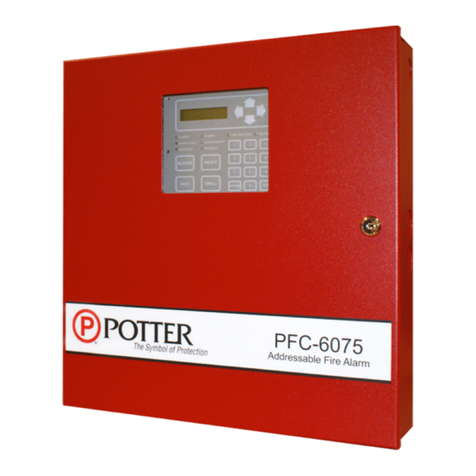
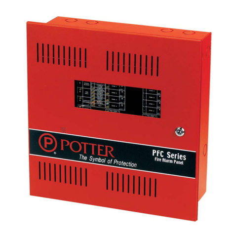
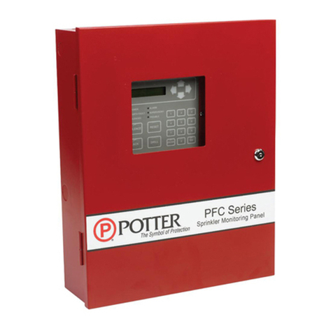
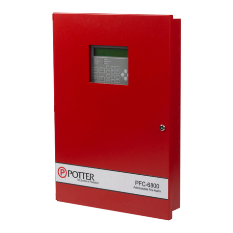
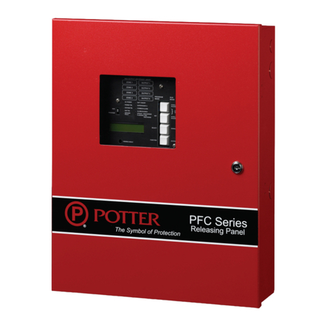
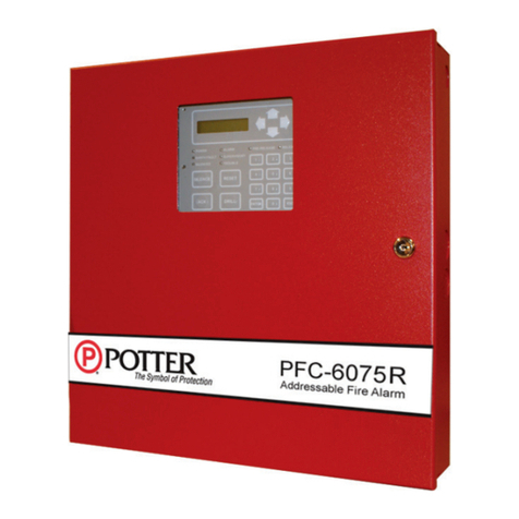
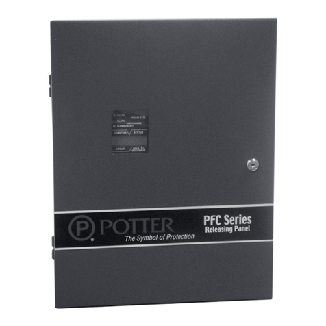
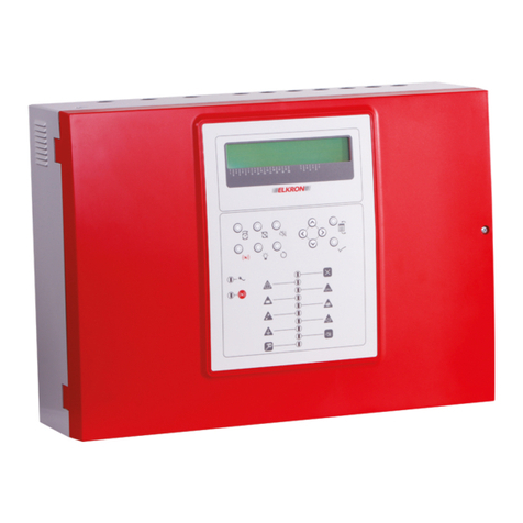
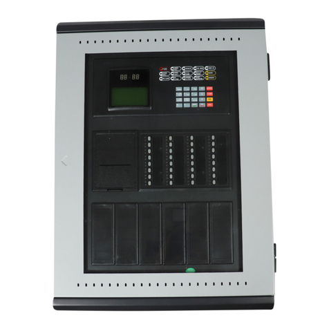
Potter PFC-6200 User manual

PFC-6200 Fire Alarm
Control Panel
Installation, Operation, & Programming Manual
Manual #5403601 Rev A
1/12
Potter Electric Signal Company, LLC
St. Louis, MO
www.pottersignal.com

2
Potter Electric Signal Company, LLC
5757 Phantom Drive Ste 125 • St. Louis, MO 63042 • 314-595-6900 • 800-325-3936
WARRANTY INFORMATION
The Aforesaid Warranty Is Expressly Made In Lieu Of Any Other Warranties, Expressed Or Implied, It
Being Understood That All Such Other Warranties, Expressed Or Implied, Including The Warranties Of
Merchantability And Fitness For Particular Purpose Are Hereby Expressly Excluded. In No Event Shall
Potter Be Liable To Purchaser For Any Direct, Collateral, Incidental Or Consequential Damages In
Connection With Purchaser’s Use Of Any Of The Products Listed Herein, Or For Any Other Cause Whatsoever
Relating To The Said Products. Neither Potter Nor Its Representatives Shall Be Liable To The Purchaser
Or Anyone Else For Any Liability, Claim, Loss, Damage Or Expense Of Any Kind, Or Direct Collateral,
Incidental Or Consequential Damages Relative To Or Arising From Or Caused Directly Or Indirectly By Said
Products Or The Use Thereof Or Any Deciency, Defect Or Inadequacy Of The Said Products. It Is Expressly
Agreed That Purchaser’s Exclusive Remedy For Any Cause Of Action Relating To The Purchase And/or Use
Of Any Of The Products Listed Herein From Potter Shall Be For Damages, And Potter's Liability For Any And
All Losses Or Damages Resulting From Any Cause Whatsoever, Including Negligence, Or Other Fault, Shall
In No Event Exceed The Purchase Price Of The Product In Respect To Which The Claim Is Made, Or At The
Election Of Potter, The Restoration Or Replacement Or Repair Of Such Product.

3
Table of Contents
Section 1: Introduction ............................................................................................................................. 1-1
..........................................................................................................................1-1
System Overview....................................................................................................................................1-1
......................................................................................................................................1-1
P-Link Accessories............................................................................................................................1-2
SLC Loop Accessories.......................................................................................................................1-2
Addressable Sensors .........................................................................................................................1-2
Addressable Modules ........................................................................................................................1-2
.........................................................................................................................1-2
............................................................................................................................1-2
Section 2: Before You Start Installation .................................................................................................. 2-3
.............................................................................................................................2-3
.................................................................................................................2-3
.......................................................................................................2-3
..........................................................................................................................2-4
.....................................................................................................................2-4
..........................................................................................................2-5
Circuit Separation.............................................................................................................................2-5
Wiring Types......................................................................................................................................2-5
................................................................................................................................2-6
...................................................................................................................2-7
Battery Circuit Calculations....................................................................................................................2-8
..............................................................................................................2-
..............................................................................................................2-10
............................................................................ 2-11
.........................................................................................................2-12
Scenario 1: Class A Loop – Isolated Devices Conguration..........................................................2-12
Scenario 2: Class B Loop – Isolated Branch Conguration ..........................................................2-13
Battery Connections..............................................................................................................................2-14
Main Supply Circuit..............................................................................................................................2-14
Section 3: Installation ............................................................................................................................. 3-15
Signaling Line Circuit (SLC) Installation.............................................................................................3-15
SLC Wiring Requirements...............................................................................................................3-15
Class B, Style 4 Wiring Conguration ............................................................................................3-15
Class A, Style 6 Wiring Conguration ............................................................................................3-16
Class A, Style 7 Wiring Conguration ............................................................................................3-17
...............................................................................................................3-17
.........................................................................................................3-18
Conventional Initiating Zones (CIZM-4) Class A...........................................................................3-18
Conventional Initiating Zones (CIZM-4) Class B...........................................................................3-18
Miniature Contact Module (MCM).................................................................................................3-19
Single Contact Module – 4 inch Mount (SCM-4) ...........................................................................3-19
Dual Contact Module – 4 inch Mount (DCM-4) ............................................................................3-19
Twin Relay Module – 4 inch mount (TRM-4)..................................................................................3-20
Monitored Output Module – 4 inch mount (MOM-4) .....................................................................3-20
Connecting Analog Sounder Base (ASB)........................................................................................3-21
Connecting Analog Relay Base (ARB)............................................................................................3-21
......................................................................................................................3-22
4
..........................................................................................3-24
NAC Wiring.....................................................................................................................................3-24
NAC Maximum Wiring Impedance Formula ..................................................................................3-24
NAC Wiring Congurations ...........................................................................................................3-24
......................................................................................................................3-26
I/O Circuits as Inputs......................................................................................................................3-26
I/O Circuits as Outputs ...................................................................................................................3-26
I/O Maximum Impedance Formula.................................................................................................3-26
Reverse Polarity Communication Line Circuit.....................................................................................3-27
...................................................................................................................3-28
.............................................................................................................................3-28
...............................................................................................3-2
......................................................................................................................................3-30
Conguration Characteristics ........................................................................................................3-30
Maximum Wire Resistance Formula...............................................................................................3-30
P-Link Addresses.............................................................................................................................3-31
..................................................................3-32
Setting Addresses ............................................................................................................................3-32
..............................................................................................................................3-33
Dip Switch Location........................................................................................................................3-34
.......................................................................................................................3-35
SLCE-127 Wiring............................................................................................................................3-35
P-Link Circuit .................................................................................................................................3-36
SLC Circuit .....................................................................................................................................3-36
SLCE Wiring Congurations ..........................................................................................................3-37
Section 4: Operation ............................................................................................................................... 4-39
Control Panel Basic Operation..............................................................................................................4-3
LCD Display ...................................................................................................................................4-39
Menu Navigation Keys....................................................................................................................4-40
Numeric Keypad..............................................................................................................................4-40
Function Pushbuttons .....................................................................................................................4-41
Status LEDs.....................................................................................................................................4-41
......................................................................................................................4-42
Section 5: Programming ......................................................................................................................... 5-43
Programming Options...........................................................................................................................5-43
Programming Overview........................................................................................................................5-46
.......................................................................................................................5-46
.............................................................................................................................5-46
LEARN Programming ..........................................................................................................................5-47
.....................................................................................................5-47
..................................................................................................................................5-4
Uploading from Panel to Computer................................................................................................5-50
............................................................................................5-51
Enable Remote Access ....................................................................................................................5-51
File New..........................................................................................................................................5-52
File Save / Save As..........................................................................................................................5-52
Audit Errors ....................................................................................................................................5-52

5
.....................................................5-54
History Reports ...............................................................................................................................5-54
Detector Sensitivity Status Reports.................................................................................................5-55
Printing Reports..............................................................................................................................5-56
.....................................................................................................................5-57
Window Regions / Areas..................................................................................................................5-57
Program Icons.................................................................................................................................5-58
.......................................................................................................5-5
.............................................................................................................................5-60
User Name / Password....................................................................................................................5-60
....................................................................................................................5-61
Job Details ......................................................................................................................................5-61
General Options..............................................................................................................................5-61
Day/Night Sensitivity Mode and Holiday Scheduling.....................................................................5-62
Users ...............................................................................................................................................5-63
......................................................................................................................5-64
P-Link E-mail Notication Requirements .......................................................................................5-65
Connecting the Panel to a Network ................................................................................................5-65
E-mail Sent from Panel ...................................................................................................................5-66
E-mail Report Requested from PC..................................................................................................5-67
Receiving E-mail Status Reports.....................................................................................................5-69
System Programming............................................................................................................................5-71
Mapping Zones Overview ...............................................................................................................5-71
Single Zones....................................................................................................................................5-71
Multiple Zones ................................................................................................................................5-71
Mapping Terminology .....................................................................................................................5-72
Zone Types / Styles..........................................................................................................................5-72
Zone Attributes................................................................................................................................5-73
Creating Zones................................................................................................................................5-75
Conguring Zones...........................................................................................................................5-76
Conguring Points..........................................................................................................................5-76
NAC Functions................................................................................................................................5-77
SLC Functions.................................................................................................................................5-78
Adding Points to Zones ...................................................................................................................5-81
Group by Area.................................................................................................................................5-83
...................................................................................................................5-84
..........................................................................................................................5-85
DACT (UD-1000)............................................................................................................................5-85
CA-6075 Class A Converter Module ..............................................................................................5-87
Remote Annunciators (RA-6500 and RA-6075)..............................................................................5-88
SLC Expansion Boards (SLCE-127) ...............................................................................................5-88
Section 6: PSN-1000 / PSN-1000(E) – Installing, Operating & Programming.................................. 6-89
.............................................................................................................................6-8
.............................................................................................................................6-8
Visual Indicators .............................................................................................................................6-89
...............................................................................................................6-8
........................................................................................................................6-8

6
............................................................................................................................6-8
Circuit Separation...........................................................................................................................6-89
Wiring Types....................................................................................................................................6-90
..............................................................................................................................0
...............................................................................................................................1
.................................................................................................................2
................................................................................................................3
Battery Circuit Calculation ...................................................................................................................3
.....................................................................4
............................................................................5
...............................................................................................6
NAC Wiring.....................................................................................................................................6-96
NAC Wiring Congurations............................................................................................................6-96
Input Circuits ........................................................................................................................................8
Conguration Characteristics ........................................................................................................6-98
Wiring to
Control Panel.......................................................................................................................... 6-99
Repeater Output ..................................................................................................................................6-100
Conguration Characteristics ......................................................................................................6-100
Maximum Wire Resistance Formula.............................................................................................6-100
.................................................................................................................6-101
Conguration Characteristics ......................................................................................................6-101
Relay Outputs......................................................................................................................................6-101
PSN-1000/PSN-1000(E) Operations ..................................................................................................6-102
Status LEDs...................................................................................................................................6-102
PSN-1000/PSN-1000(E) Programming..............................................................................................6-103
Adding a Power Supply.................................................................................................................6-103
Deleting a Power Supply ..............................................................................................................6-104
Section 7: IP Communication .............................................................................................................. 7-105
...................................................................................................7-106
IP Reporting Accounts ..................................................................................................................7-106
Appendix A: Basic Operating Instructions............................................................................................ A-1
Appendix B: Modem Connectivity Setup ...............................................................................................B-1
Appendix C: System Maintenance and Testing..................................................................................... C-1
Appendix D: PSN-1000/PSN-1000(E) Maintenance and Testing......................................................... D-1
Appendix E: Compatible Devices Table ..................................................................................................E-1
Appendix F: Troubleshooting Tips ..........................................................................................................F-1
Appendix G: Control Panel Menu .......................................................................................................... G-1

1-1
Section 1: Introduction
Purpose of This Manual
System Overview
System Features
Built in Sync
Built in Sync
Contact Input
Potter

1-2
Maintenance Alert
P-Link Accessories
SLC Loop Accessories
How to Use this Manual
Common Terminology
TerminologyTable 1:
Term Denition
Enclosure
EOLR
Remote Annunicator
NAC
SLC Signaling Line Circuit

2-3
Section 2: Before You Start Installation
System Specications
Cabinet Description
y
y
Visual Indicators
y
y
LCD Description
y
Environmental Specications
y
y
y
y
components.
y
System Congurations / Appliances
System Congurations / AppliancesTable 2:
Model Description Local Auxiliary Remote
Station
Central
Station Proprietary
YYYY Y
CA-6075 OOOO O
N N Y Y Y
RA-6500 or
RA-6075 OOOO O
PSN-1000 or
PSN-1000(E) OOOO O
SLCE-127 OOOO O
3005013 YYYY Y
3005012 N Y N N N

2-4
Electrical Specications
System Panel Electrical SpecicationsTable 3:
Panel # NACs Rating
per NAC
I/O Circuits
(As Outputs) SLC Power Notes Style and Class
NACs
3 Amp 1 Amp
SLC Loop,
using a SLCE-127
SLC – Class A or B
NAC – Class A or B
I/O – Class B only
System Size Specications
System Size SpecicationsTable 4:
Accessories/Subassemblies Maximum System Size
•y
•y
•y
•y

2-5
Main Board Wiring Specications
before
Circuit Separation
ymustmust
y
Wiring Types
Main Board Circuit Wiring TypesTable 5:
Wiring Type
Type of Circuit Voltage Power
AC Connection
Battery Connection
Supervisory Relay
Alarm Relay
I/O Circuits
Signaling Line Circuit

2-6
Cabinet Dimensions
PFC-6200 Cabinet DimensionsFigure 1.
27.32 “
26.00 “
4.41”
3.75“
17.60”
18.91”
BOTTOM
RIGHT SIDE
DEPTH
DEPTH
TOP
LEFT SIDE
DWG #602-1

2-7
Cabinet Wiring Connections
PFC-6200 Cabinet WiringFigure 2.
POWER ALARM
SUPERVISORY
TROUBLE
EARTH FAULT
SILENCE
ACK DRILL
RESET
SILENCE
Non-power
limited battery
connection
120VAC 50Hz-60Hz
240VAC 50Hz-60Hz
Connect to separate
unswitched AC circuits
Power limited
wiring
DWG #602-2A
High voltage
phone connections
Optional CA-6075
Class A Expander
Non-power limited
relay connection
Optional
UD-1000 DACT

2-8
Battery Circuit Calculations
Battery Calculation Worksheet1.
SLC Current Draw Worksheets2.
SLC Current Draw Worksheets for SLCE-127s (optional)3.

Battery Calculation Worksheets
Description Quantity Standby
(mA)
Total
Standby (mA)
Alarm
(mA)
Total
Alarm (mA)
1 130 220
20 25
20 50
12 44
16 23
15 15
NAC 1
NAC 2
I/O 1
I/O 2
"SLC Current Draw
Worksheet"
SLC Loop#___
SLC Loop#___
Convert to Amps Convert to Amps
Alarm time (minutes)
Example:
5 minute alarm: enter 12
10 minute alarm: enter 6
÷ ____
÷ 0.85
Required AH
7 AH .230 A
33 AH 1.151 A
Important Notes:

2-10
SLC Current Draw Worksheet
Device Type Qty Standby
(mA)
Total
Standby
(mA)
Alarm
(mA)
Total
Alarm
(mA)
0.325 0.325
0.325 0.325
0.325 0.325
0.325 0.325
0.325 0.325
*Note 1 0.325 1.000
0.325 0.325
0.325 1.000
0.325 1.000
0.325 1.000
0.325 1.000
0.325 2.34
0.325 0.325
0.325 0.325
0.325 2.34
n/a n/a n/a 27.0
SLC Standby
Current
SLC Alarm
Current

2-11
SLC #___ Current Draw Worksheet for SLCE-127s
Device Type Qty Standby
(mA)
Total
Standby
(mA)
Alarm
(mA)
Total
Alarm
(mA)
160 60 60 60
0.325 0.325
0.325 0.325
0.325 0.325
0.325 0.325
0.325 0.325
0.325 1.000
0.325 0.325
0.325 1.000
0.325 1.000
0.325 1.000
0.325 1.000
0.325 2.34
0.325 0.325
0.325 0.325
0.325 2.34
n/a n/a n/a 27.0
SLC Standby
Current
SLC Alarm
Current

2-12
Isolator Device Load Calculation
Scenario 1: Class A Loop – Isolated Devices Conguration
Formula: Total # addressable devices + Total # isolators = Total power unit allocations (or device load)
Example of a Class A Loop – Isolated BranchesFigure 3.
Conguration Summary:
Total addressable devices = 8 (sensors only) out of 127 possible addressable points.
Total device load = 17 (calculated as follows: 8 sensors + 9 isolators) out of 127 power unit allocations.
Example: If a conguration uses 75 sensors, up to 52 isolators may be supported.
Solution: 127 - 75 = 52
LEGEND:
ISO Module/
Device
Sensor
PANEL
To tal addressable
devices = 8
To tal isolators = 9
DWG # 593-4

2-13
Scenario 2: Class B Loop – Isolated Branch Conguration
Device Load Rule for Branch Congurations
Example of a Class B Loop – Isolated BranchesFigure 4.
Conguration Summary:
Total addressable devices = 15 (sensors only) out of 127 addressable points.
Total device load = 34 out of a possible 127 power unit allocations.
LEGEND:
ISO Module/
Device
Sensor
BRANCH #1
BRANCH #2
BRANCH #3
BRANCH #4
PANEL
Total devices = 3
Total devices = 2
Total devices = 10
Total devices = 4
DWG #593-3

2-14
Battery Connections
Note
PFC-6200 Battery Connections Figure 5.
Panel
Connections
BATTERY
-+
12 V
Battery
-+
12 V
Battery
-+
DWG # 593-5
Main Supply Circuit
PFC-6200 AC TerminalsFigure 6.
BWG
AC120 V/AC230V,50/60Hz
AC POWER
Black
White
Ground
120VAC 50/60 Hz
240VAC 50/60 Hz
Connect to separate
Unswitched AC circuit
•y
•y
Table of contents
Other Potter Control Panel manuals

Potter
Potter PFC-4410RC Instruction Manual

Potter
Potter PFC 2000RC User manual

Potter
Potter PFC-6800 Owner's manual

Potter
Potter PFC-3002T User manual

Potter
Potter PFC-3005T User manual

Potter
Potter PFC-4064 Operating instructions

Potter
Potter PFC-8000 Series User manual

Potter
Potter PFC-5000 Series User manual

Potter
Potter PFC-6075R Owner's manual

Potter
Potter PFC-6006 Owner's manual