Woodward RP-3000 User manual

RP-3000
Manual Remote Panel
RP-3000
Software Version 1.xxxx or higher
37534C

© 2013
Designed in Germany
Woodward GmbH
Handwerkstrasse 29
70565 Stuttgart
Germany
Telephone: +49 (0) 711 789 54-510
Fax: +49 (0) 711 789 54-101
email: [email protected]
Internet: http://www.woodward.com
37534CRP-3000 | Remote Panel2

Brief Overview
Fig. 1: RP-3000 Remote Panel
1 CAN bus interface connector
2 Power supply
3 Protective earth PE
4 Relay output terminal
5 RS-232 interface connector
The RP-3000 is a remote control and annunciation panel for use
with the back-panel mounted easYgen-3100/3400 or door-mounted
easYgen-3200/3500 genset controls.
It has the same look and feel of the easYgen-3200/3500 genset
control, enabling user-friendly transition between genset control
sources.
Each RP-3000 remote panel communicates with a single
easYgen-3000 Series genset control.
The following easYgen-3000 genset controls are supported by the
RP-3000 remote panel:
RP-3000 P/N 8446-1048 P/N 8446-1046
easYgen-3100/3200
Package P11 / Package P22
3---
easYgen-3400/3500
Package P1 / Package P2
3---
easYgen-3400/3500 Marine
Package P1
--- 3
1 easYgen-3100/3200 Package P1 software version
1.15xx or higher.
2 easYgen-3100/3200 Package P2 software version
1.13xx or higher.
Supported devices
Brief Overview
37534C RP-3000 | Remote Panel 3

Fig. 2: Sample application setup
1 Only one easYgen can be connected at once.
A typical application for the remote panel is to control back-panel
mounted easYgen-3100/3400 devices.
nIn this case, the RP-3000 provides control from the front panel
with considerably reduced wiring effort.
nThe high-voltage connections are located safely on the back
panel.
For a listing of additional applications and setups
please refer to chapter Ä Chapter 6 “Application”
on page 61.
The following parts are included in the scope of delivery. Please
check prior to the installation that all parts are present.
Sample application setup
Scope of delivery
Brief Overview
37534CRP-3000 | Remote Panel4

Fig. 3: Scope of delivery - schematic
A RP-3000 remote panel
B Product CD (configuration software and manual)
C Clamp fastener installation material - 4x
D Screw kit installation material - 12x
CAUTION!
The stop button function reacts in some screens not as
fast as the stop button of the easYgen-3200/3500.
Therefore it can be necessary to install an external
emergency stop button.
The remote panel RP-3000 is connected via a serial interface to
the genset control. Please keep in mind that the involved
refreshing times of the displayed data are slower on the RP-3000
compared to the easYgen-3200/3500.
The RP-3000 has following constraints compared to the
easYgen-3200/3500.
Section Constraint
General The page reproduction takes a bit longer when you
change or scroll pages.
During page reproduction no buttons are accepted.
As long as an hour glass is displayed no buttons are
accepted.
Alarm list The alarms in the active alarm list are displayed
about one second delayed.
Event History Is the event history page directly accessed after
switching on the supply voltage, it can last a couple of
minutes until the events are displayed. During this
time the acceptance of the STOP button and also
leaving the event page is delayed for a couple of sec‐
onds.
Display J1939 At the access of the analog values J1939 firstly a
hour glass is displayed. During this time no buttons
are accepted.
Constraints compared to
easYgen-3200/3500
Brief Overview
37534C RP-3000 | Remote Panel 5

Section Constraint
Setpoints The acceleration levels for changing the active power
setpoints with up/down buttons are a bit delayed
compared to easYgen-3200/3500.
Display of free configu‐
rable text
Every time you switch on the supply voltage of the
RP-3000 all free configurable texts are initially shown
as default text. In the background starts an automatic
import process – replacing the default text by the free
configurable text (loaded from the connected
easYgen). This process lasts up to 20 seconds.
If the free configurable texts are changed in an
already running system, it will last up to 2 hours until
the changes are visible.
Brief Overview
37534CRP-3000 | Remote Panel6

Table of contents
1General Information................................................................................................................ 11
1.1 About This Manual.................................................................................................................... 11
1.1.1 Revision History........................................................................................................................ 11
1.1.2 Depiction Of Notes And Instructions......................................................................................... 11
1.2 Copyright And Disclaimer.......................................................................................................... 12
1.3 Service And Warranty............................................................................................................... 13
1.4 Safety........................................................................................................................................ 13
1.4.1 Intended Use............................................................................................................................. 13
1.4.2 Personnel.................................................................................................................................. 14
1.4.3 General Safety Notes................................................................................................................ 15
1.4.4 Protective Equipment And Tools............................................................................................... 18
2 System Overview..................................................................................................................... 19
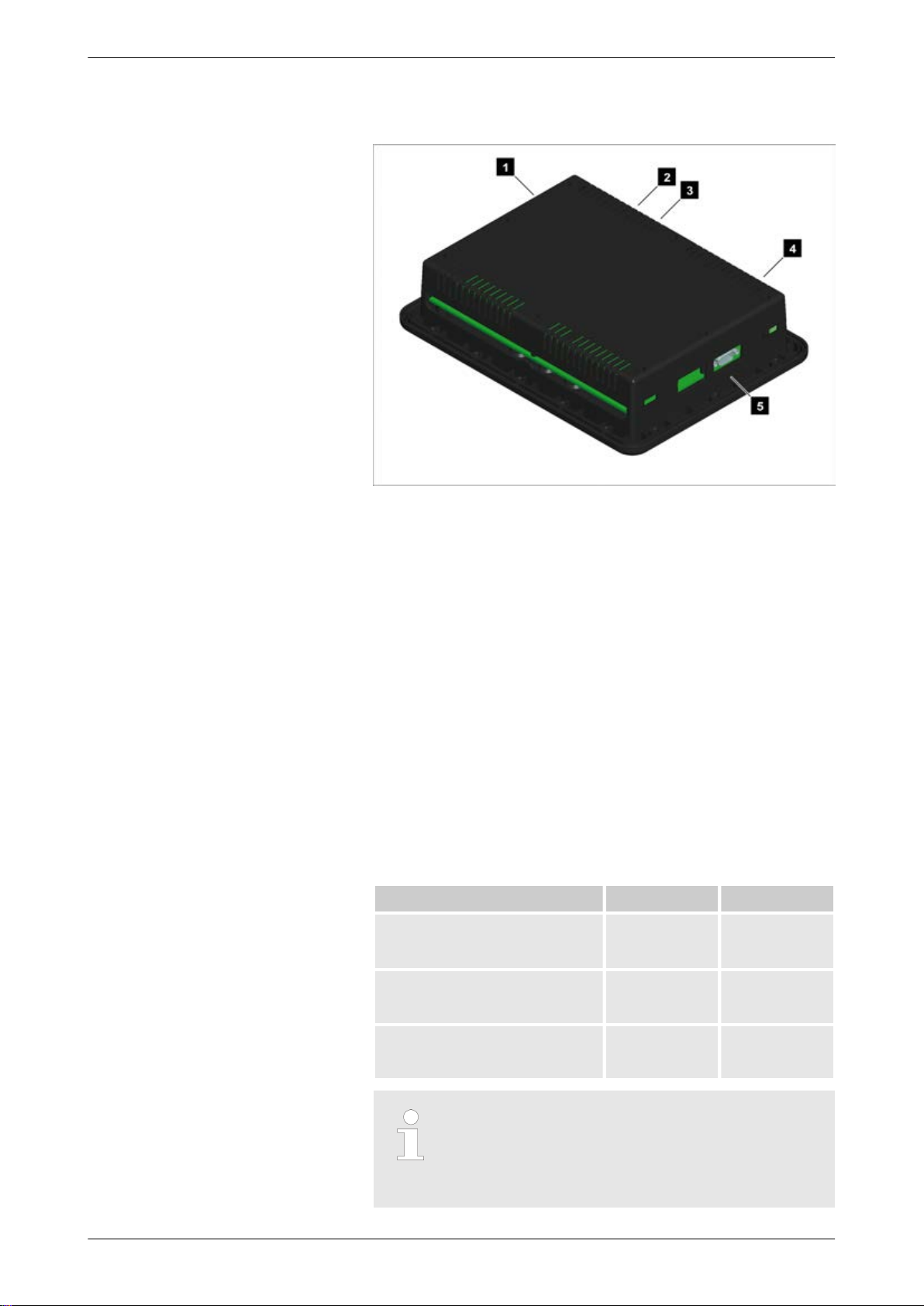
2.1 Display And Status Indicators................................................................................................... 19
2.2 Hardware Interfaces (Terminals)............................................................................................... 19
2.3 Device Update........................................................................................................................... 20
2.3.1 Software Version....................................................................................................................... 20
2.3.2 Update....................................................................................................................................... 22
2.3.3 Troubleshooting......................................................................................................................... 24
3 Installation............................................................................................................................... 27
3.1 Mount Unit (Plastic Housing)..................................................................................................... 27
3.1.1 Clamp Fastener Installation....................................................................................................... 28
3.1.2 Screw Kit Installation................................................................................................................. 29
3.2 Setup Connections.................................................................................................................... 31
3.2.1 Terminal Allocation.................................................................................................................... 31
3.2.2 Wiring Diagram.......................................................................................................................... 32
3.2.3 Power Supply............................................................................................................................ 33
3.2.4 Relay Output............................................................................................................................. 34
3.2.5 Serial Interface.......................................................................................................................... 34
3.2.5.1 RS-232 Interface....................................................................................................................... 34
3.3 CAN Bus Interface..................................................................................................................... 35
4 Configuration........................................................................................................................... 39
4.1 Basic Setup............................................................................................................................... 39
4.1.1 Configure Language.................................................................................................................. 39
4.1.2 Configure Display...................................................................................................................... 39
4.1.3 Lamp Test................................................................................................................................. 39
4.1.4 Enter Password......................................................................................................................... 40
4.1.5 Password System...................................................................................................................... 42
Table of contents
37534C RP-3000 | Remote Panel 7

4.2 Configure CAN Interface........................................................................................................... 42
4.2.1 Connection CAN Interface 2 (easYgen-3000)........................................................................... 42
4.2.1.1 Setup Parameters RP-3000...................................................................................................... 42
4.2.1.2 Setup Parameters easYgen-3000 Series.................................................................................. 45
4.2.2 Connection CAN Interface 1 (easYgen-3000)........................................................................... 49
4.2.2.1 Setup Parameters RP-3000...................................................................................................... 49
4.2.2.2 Setup Parameters easYgen-3000 Series.................................................................................. 51
5 Operation................................................................................................................................. 57
5.1 Basic Navigation........................................................................................................................ 57
5.2 Specialised RP-3000 Menu Screens......................................................................................... 57
5.3 Relay Output............................................................................................................................. 59
6 Application............................................................................................................................... 61
6.1 Overview................................................................................................................................... 61
6.2 Connection CAN Interface 2...................................................................................................... 62
6.3 Connection CAN Interface 1...................................................................................................... 62
7 Interfaces And Protocols........................................................................................................ 65
7.1 Interfaces Overview................................................................................................................... 65
7.2 CAN Interfaces.......................................................................................................................... 65
7.2.1 CAN Interface 1 (Guidance level).............................................................................................. 65
7.3 Serial Interfaces........................................................................................................................ 65
7.3.1 RS-232 Interface (Serial Interface 1)......................................................................................... 65
8 Technical Specifications........................................................................................................ 67
8.1 Technical Data.......................................................................................................................... 67
8.1.1 Ambient Variables..................................................................................................................... 67
8.1.2 Inputs/Outputs........................................................................................................................... 68
8.1.3 Interface.................................................................................................................................... 68
8.1.4 Battery....................................................................................................................................... 68
8.1.5 Housing..................................................................................................................................... 68
8.1.6 Approvals.................................................................................................................................. 69
8.1.7 Generic Note............................................................................................................................. 69
8.2 Environmental Data................................................................................................................... 69
9 Appendix.................................................................................................................................. 71
9.1 Additional Information................................................................................................................ 71
9.1.1 D-SUB Connector Housing....................................................................................................... 71
9.1.2 CAN Bus Pin Assignments Of Third-Party Units....................................................................... 71
10 Glossary And List Of Abbreviations...................................................................................... 73
Table of contents
37534CRP-3000 | Remote Panel8

Table of contents
37534CRP-3000 | Remote Panel10

1 General Information
1.1 About This Manual
1.1.1 Revision History
Rev. Date Editor Changes
C 2013-08-30 GG Device
nSoftware is updated to work withthe latest easYgen-3000 standard devices.
nNew software on CD-ROM to work with all easYgen-3000 devices.
Manual
nThe table that describes the correlation of the factory set (new) software numbers of the
Remote Panel and the easYgen-3000 is updated. Refer to
Ä Chapter 2.3.1 “Software Ver‐
sion” on page 20
for details.
nMinor changes.
B 2012-12-12 GG Device
nNew software to work with latest easYgen-3000 standard devices.
nNew software on CD-ROM to work with all easYgen-3000 devices.
Manual
nThe table that describes the correlation of the factory set (new) software numbers of the
Remote Panel and the easYgen-3000 is updated. Refer to
Ä Chapter 2.3.1 “Software Ver‐
sion” on page 20
for details.
nMinor changes.
A 2012-07-23 GG Device
nNew unit display language available on parameter 1700: Swedish.
Manual
nAll available display languages are listed. Refer to parameter 1700 Ä p. 39 for more
details.
nMinor changes.
NEW 2011-09-12 TE Manual
nRelease
1.1.2 Depiction Of Notes And Instructions
Safety instructions are marked with symbols in these instructions.
The safety instructions are always introduced by signal words that
express the extent of the danger.
DANGER!
This combination of symbol and signal word indicates
an immediately-dangerous situation that could cause
death or severe injuries if not avoided.
WARNING!
This combination of symbol and signal word indicates
a possibly-dangerous situation that could cause death
or severe injuries if it is not avoided.
Safety instructions
General Information
About This Manual > Depiction Of Notes And Ins...
37534C RP-3000 | Remote Panel 11

CAUTION!
This combination of symbol and signal word indicates
a possibly-dangerous situation that could cause slight
injuries if it is not avoided.
NOTICE!
This combination of symbol and signal word indicates
a possibly-dangerous situation that could cause prop‐
erty and environmental damage if it is not avoided.
This symbol indicates useful tips and recommenda‐
tions as well as information for efficient and trouble-
free operation.
To emphasize instructions, results, lists, references, and other ele‐
ments, the following markings are used in these instructions:
Marking Explanation
Step-by-step instructions
ðResults of action steps
References to sections of these instructions and to
other relevant documents
Listing without fixed sequence
[Buttons]
Operating elements (e.g. buttons, switches), display
elements (e.g. signal lamps)
“Display”
Screen elements (e.g. buttons, programming of func‐
tion keys)
1.2 Copyright And Disclaimer
Disclaimer
All information and instructions in this operating manual have been
provided under due consideration of applicable guidelines and reg‐
ulations, the current and known state of the art, as well as our
many years of in-house experience. Woodward GmbH assumes no
liability for damages due to:
nFailure to comply with the instructions in this operating manual
nImproper use / misuse
nWillful operation by non-authorized persons
nUnauthorized conversions or non-approved technical modifica‐
tions
nUse of non-approved spare parts
Tips and recommendations
Additional markings
General Information
Copyright And Disclaimer
37534CRP-3000 | Remote Panel12

The originator is solely liable to the full extent for damages caused
by such conduct. The agreed upon obligations in the delivery con‐
tract, the general terms and conditions, the manufacturer’s delivery
conditions, and the statutory regulations valid at the time the con‐
tract was concluded, apply.
Copyright
This operating manual is protected by copyright. No part of this
operating manual may be reproduced in any form or incorporated
into any information retrieval system without written permission of
Woodward GmbH.
Delivery of the operating manual to third parties, duplication in any
form - including excerpts - as well as exploitation and/or communi‐
cation of the content, are not permitted without a written declara‐
tion of release by Woodward GmbH.
Actions to the contrary exact damage compensation. We reserve
the right to enforce additional claims.
1.3 Service And Warranty
Our Customer Service is available for technical information.
Please see page 2 for the contact data.
In addition, our employees are constantly interested in new infor‐
mation and experiences that arise from usage and could be val‐
uable for the improvement of our products.
Please enquire about the terms of warranty from your
nearest Woodward representative.
For our contact search webpage please go to:
http://www.woodward.com/Directory.aspx
1.4 Safety
1.4.1 Intended Use
The remote panel unit has been designed and constructed solely
for the intended use described in this manual.
The remote panel connected to the genset control unit must be used exclusively
for engine-generator system management applications.
nIntended use requires operation of the control unit within the specifications
listed in
Ä Chapter 8.1 “Technical Data” on page 67
.
nAll permissible applications are outlined in
Ä Chapter 6 “Application”
on page 61
.
nIntended use also includes compliance with all instructions and safety notes
presented in this manual.
nAny use which exceeds or differs from the intended use shall be considered
improper use.
nNo claims of any kind for damage will be entertained if such claims result
from improper use.
Warranty terms
General Information
Safety > Intended Use
37534C RP-3000 | Remote Panel 13

NOTICE!
Damage due to improper use!
Improper use of the remote panel unit may cause
damage to the control unit as well as connected com‐
ponents.
Improper use includes, but is not limited to:
– Operation outside the specified operation condi‐
tions.
1.4.2 Personnel
WARNING!
Hazards due to insufficiently qualified personnel!
If unqualified personnel perform work on or with the
control unit hazards may arise which can cause
serious injury and substantial damage to property.
– Therefore, all work must only be carried out by
appropriately qualified personnel.
This manual specifies the personnel qualifications required for the
different areas of work, listed below:
The workforce must only consist of persons who can be expected
to carry out their work reliably. Persons with impaired reactions due
to, for example, the consumption of drugs, alcohol, or medication
are prohibited.
When selecting personnel, the age-related and occupation-related
regulations governing the usage location must be observed.
General Information
Safety > Personnel
37534CRP-3000 | Remote Panel14

1.4.3 General Safety Notes
DANGER!
Life-threatening hazard from electric shock!
There is an imminent life-threatening hazard from elec‐
tric shocks from live parts. Damage to insulation or to
specific components can pose a life-threatening
hazard.
– Only a qualified electrician should perform work on
the electrical equipment.
– Immediately switch off the power supply and have
it repaired if there is damage to the insulation.
– Before beginning work at live parts of electrical
systems and resources, cut the electricity and
ensure it remains off for the duration of the work.
Comply with the five safety rules in the process:
– cut electricity;
– safeguard against restart;
– ensure electricity is not flowing;
– earth and short-circuit; and
– cover or shield neighbouring live parts.
– Never bypass fuses or render them inoperable.
Always use the correct amperage when changing
fuses.
– Keep moisture away from live parts. Moisture can
cause short circuits.
WARNING!
Hazards due to insufficient prime mover protection
The engine, turbine, or other type of prime mover
should be equipped with an overspeed (overtempera-
ture, or overpressure, where applicable) shutdown
device(s), that operates totally independently of the
prime mover control device(s) to protect against run‐
away or damage to the engine, turbine, or other type of
prime mover with possible personal injury or loss of life
should the mechanical-hydraulic gov-ernor(s) or elec‐
tric control(s), the actuator(s), fuel control(s), the
driving mechanism(s), the linkage(s), or the controlled
device(s) fail.
Electrical hazards
Prime mover safety
General Information
Safety > General Safety Notes
37534C RP-3000 | Remote Panel 15

WARNING!
Hazards due to unauthorized modifications
Any unauthorized modifications to or use of this equip‐
ment outside its specified mechanical, electrical, or
other operating limits may cause personal injury and/or
property damage, including damage to the equipment.
Any unauthorized modifications:
– constitute "misuse" and/or "negligence" within the
meaning of the product warranty thereby excluding
warranty coverage for any resulting damage
– invalidate product certifications or listings.
NOTICE!
Damage to the control system due to improper
handling
Disconnecting a battery from a control system that
uses an alternator or battery-charging device whilst the
charging device is still connected causes damage to
the control system.
– Make sure the charging device is turned off before
disconnecting the battery from the system.
Protective equipment: nESD wrist band
NOTICE!
Damage from electrostatic discharge
All electronic equipment sensitive to damage from
electrostatic discharge, which can cause the control
unit to malfunction or fail.
– To protect electronic components from static
damage, take the precautions listed below.
1. Avoid build-up of static electricity on your body by not
wearing clothing made of synthetic materials. Wear cotton or
cotton-blend materials as much as possible because these
do not store static electric charges as easily as synthetics.
2. Before any maintenance work on the control unit, ground
yourself by touching and holding a grounded metal object
(pipes, cabinets, equipment, etc.) to discharge any static
electricity.
Alternatively wear an ESD wrist band connected to ground.
3. Keep plastic, vinyl, and Styrofoam materials (such as plastic
or Styrofoam cups, cigarette packages, cellophane wrappers,
vinyl books or folders, plastic bottles, etc.) away from the
control unit, modules and work area.
Modifications
Use of batteries/alternators
Electrostatic discharge
General Information
Safety > General Safety Notes
37534CRP-3000 | Remote Panel16

4. Opening the control cover may void the unit warranty. Do not
remove the printed circuit board (PCB) from the control cab‐
inet unless instructed by this manual.
If instructed by this manual to remove the PCB
from the control cabinet, follow these precau‐
tions:
–
Ensure that the device is completely voltage-
free (all connectors have to be discon‐
nected).
–
Do not touch any part of the PCB except the
edges.
–
Do not touch the electrical conductors, con‐
nectors, or components with conductive
devices or with bare hands.
–
When replacing a PCB, keep the new PCB in
the plastic antistatic protective bag it comes
in until you are ready to install it. Immediately
after removing the old PCB from the control
cabinet, place it in the antistatic protective
bag.
For additional information on how to prevent damage
to electronic components caused by improper han‐
dling, read and observe the precautions in:
–
"Woodward manual 82715, Guide for Handling and
Protection of Electronic Controls, Printed Circuit
Boards, and Modules".
Marine usage of the RP-3000 connected to the easYgen genset
control requires additional precautions as listed below:
The specified marine approvals are initially only valid
for metal housing units. They are only valid for plastic
housing units, if they are installed using the screw kit .
–
Use all 12 screws and tighten accordingly.
nThe RP-3000 has an internally isolated power supply.
NOTICE!
Malfunctions due to insufficient protection against
electromagnetic interference
Exposure to increased electromagnetic interference on
bridge and deck zones may cause malfunctions or
incorrect internal readings.
– Install an EMI filter (i.e. TIMONTA FSS2-65-4/3) for
the power supply inputs when using the control
unit on bridge and deck zones.
Notes on marine usage
General Information
Safety > General Safety Notes
37534C RP-3000 | Remote Panel 17

Some additional, independent safety and protection
devices are necessary to meet safety requirements of
Rules and Regulations of marine Classification Soci‐
eties.
–
Please refer to the corresponding documents
issued by marine Classification Societies for the
applicable reqiurements.
The RP-3000 is type approved by LR Lloyd's Register.
–
Please consider for final functional arrangements
to comply with appropriate Lloyd's Register Rules
as subject of the Plan Approval process.
1.4.4 Protective Equipment And Tools
Personal protective equipment serves to protect risks to the safety
and health of persons as well as to protect delicate components
during work.
Certain tasks presented in this manual require the personnel to
wear protective equipment. Specific required equipment is listed in
each individual set of instructions.
The cumulative required personal protective equipment is detailed
below:
ESD wrist band
The ESD (electrostatic discharge) wrist band keeps the user's
body set to ground potential. This measure protects sensitive elec‐
tronic components from damage due to electrostatic discharge.
Use of the proper tools ensures successful and safe execution of
tasks presented in this manual.
Specific required tools are listed in each individual set of instruc‐
tions.
The cumulative required tools are detailed below:
Torque screwdriver
A torque-screwdriver allow fastening of screws to a precisely speci‐
fied torque.
nNote the required torque range indiviually specified in the tasks
listed in this manual.
Protective gear
Tools
General Information
Safety > Protective Equipment And T...
37534CRP-3000 | Remote Panel18

2 System Overview
This chapter provides a basic overview of the remote panel unit.
Refer to the comprehensive chapters indicated below to commis‐
sion the control unit:
n
Ä Chapter 3 “Installation” on page 27
provides information on
how to mount the unit and setup connections.
n
Ä Chapter 4 “Configuration” on page 39
provides information
on basic setup and reference information on all configurable
parameters.
n
Ä Chapter 5 “Operation” on page 57
provides information on
how to access the unit via the front panel.
n
Ä Chapter 6 “Application” on page 61
provides application
examples as well as instructions for the corresponding required
configuration.
n
Ä Chapter 7 “Interfaces And Protocols” on page 65
provides
reference information on the usage of the interfaces and proto‐
cols provided by the control unit.
2.1 Display And Status Indicators
The display (Fig. 4) as part of the RP-3000 is used for direct
access to status information and configuration.
For information on the usage of the graphical user
interface refer to Ä Chapter 5 “Operation” on page 57.
2.2 Hardware Interfaces (Terminals)
The RP-3000 (Fig. 5) provides the following terminals.
RP-3000 display
Fig. 4: Display
System Overview
Hardware Interfaces (Termina...
37534C RP-3000 | Remote Panel 19

Fig. 5: RP-3000 Remote Panel
1 CAN bus interface connector
2 Power supply
3 Protective earth PE
4 Relay output terminal
5 RS-232 interface connector
For information on how to setup connections refer to
Ä Chapter 3.2 “Setup Connections” on page 31.
For information on the interfaces and protocols refer to
Ä Chapter 7 “Interfaces And Protocols” on page 65.
2.3 Device Update
Please read the following chapter carefully to make sure that your
RP-3000 remote panel has the correct software version installed.
The following section is not valid, if you use a
easYgen-3400/3500 Marine genset control with an
RP-3000 remote panel (P/N 8446-1046). This two
devices have always the correct device software
installed.
2.3.1 Software Version
The device software of the RP-3000 remote panel and the
easYgen-3000 Series genset control are closely linked together.
This means that the software of both devices always needs to fit
together to make the entire system work correctly.
General notes
General notes
System Overview
Device Update > Software Version
37534CRP-3000 | Remote Panel20
Other manuals for RP-3000
1
Table of contents
Other Woodward Control Panel manuals
Popular Control Panel manuals by other brands

Twin-Star International
Twin-Star International DFS-220 quick guide

HEIDENHAIN
HEIDENHAIN MANUALPLUS 4110 manual

NTEK Systems
NTEK Systems DoorPad quick start guide

CBE
CBE PC-100 instruction manual

WimTec
WimTec OCEAN T6 Installation and operating instructions

Sky Laboratories
Sky Laboratories SPG 84 installation manual