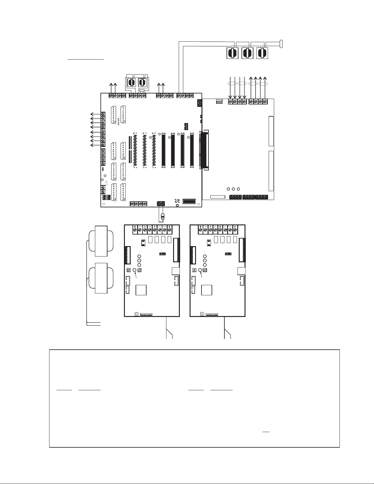
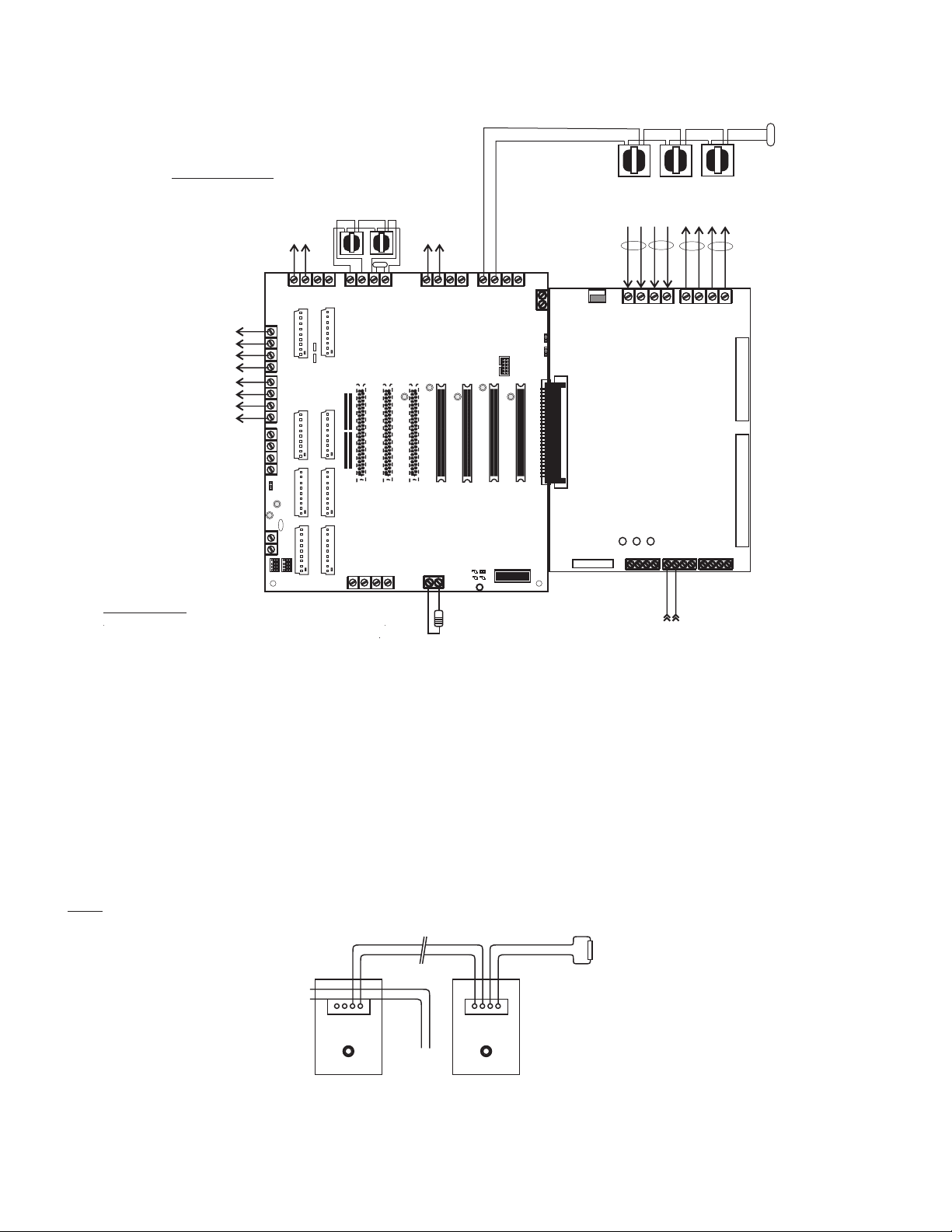
All wiring with exception of
120 VAC and Battery Connection
is Power-Limited.
Route AC power and Battery
wires to bottom-left or lower-left
side K.O.
*1
All Power Limited wiring must
maintain a min. 1/4“ separation
from Non Power Limited wiring.
(This requirement may be waived if
Type FPL, FPLR or FPLP wire is used
for Power Limited circuits)
TB1 TB2
TB3 TB4 TB5P1
P2
P3
P4
J3
1
2
3
LED3LED2LED1
NetCom Bus
*A *A
*A - Optional wiring for
Style 7 supervision
+-+-
120 VAC
(Supervised)
*1
24V Battery
(Supervised)
*1
F
I
R
E
E
O
L
EOLR
F
I
R
E
F
I
R
E
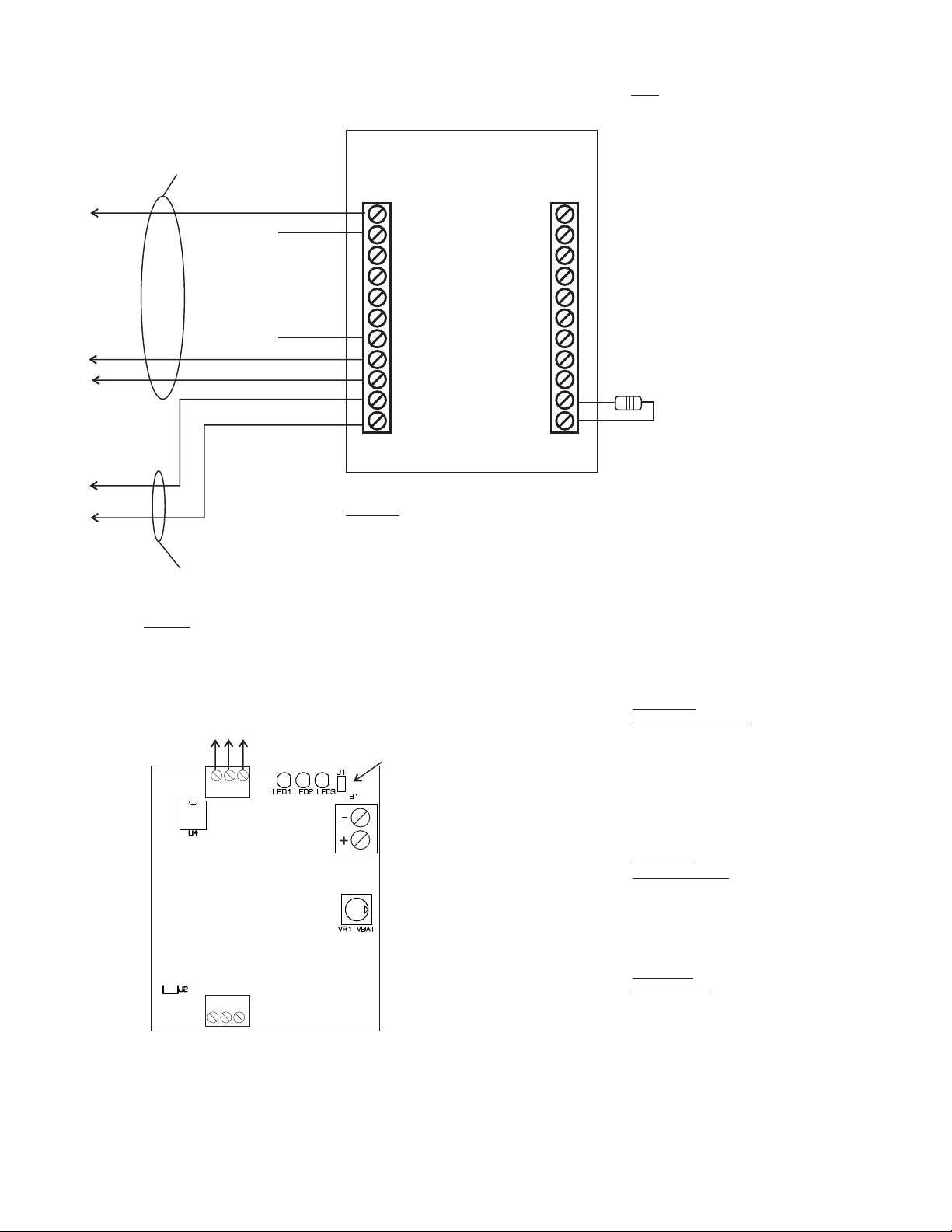
Standard Life Safety Speakers, Strobes connected and powered separately.
Ground faults are indicated at 10K impedance or less.
Break wire to maintain supervision. Do not loop wire around speaker terminals.
CLASS “B” (Style “Y”)
WIRING
Supervised - Power Limited
Fire
Phone
Loop
F
I
R
E
F
I
R
E
EOL
CLASS “A” (Style “Z”)
WIRING
Supervised
Power Limited
Matching
EOLR
MBR
TB2 TB3 TB4
TB10
J5
J6
J7
TB9
TB5 TB6 TB7
TB8
TB11
1 2 3 4
TB1
1 2 3 4 1 2 3 4 1 2 3 4
1 2 3 4 1 2 3 4 1 2 3 4
J8
J11
J9
J1
J2
J3
J4
LED1
P9
P10
P11
P12
P13
P14
P15
P16
P1 P2 P3 P4 P5 P6 P7 P8
31
1
2
3
4
50W Maximum
Speaker line EOLR must be
equal to Matching EOLR
installed on TB9. All must be
Listed EOL devices.
SPEAKER OUTPUT
PVC-25E
PVC-50E
PVC-100E
TB1
1 2 3 45 6 7 8
TB3
1
2
3
4
5
6
7
8
MESSAGE
GAIN
MIC
GAIN
FAULT
NORMAL
ALARM
YEL
GRN
RED
TB2
1
2
3
4
5
6
7
8
9
10
11
P2
S1
SN1
1 2 3
J2
J1
1
2
PVC-25E
PVC-50E
PVC-100E
TB1
1 2 3 45 6 7 8
TB3
1
2
3
4
5
6
7
8
MESSAGE
GAIN
MIC
GAIN
FAULT
NORMAL
ALARM
YEL
GRN
RED
TB2
1
2
3
4
5
6
7
8
9
10
11
P2
S1
SN1
1 2 3
J2
J1
1
2
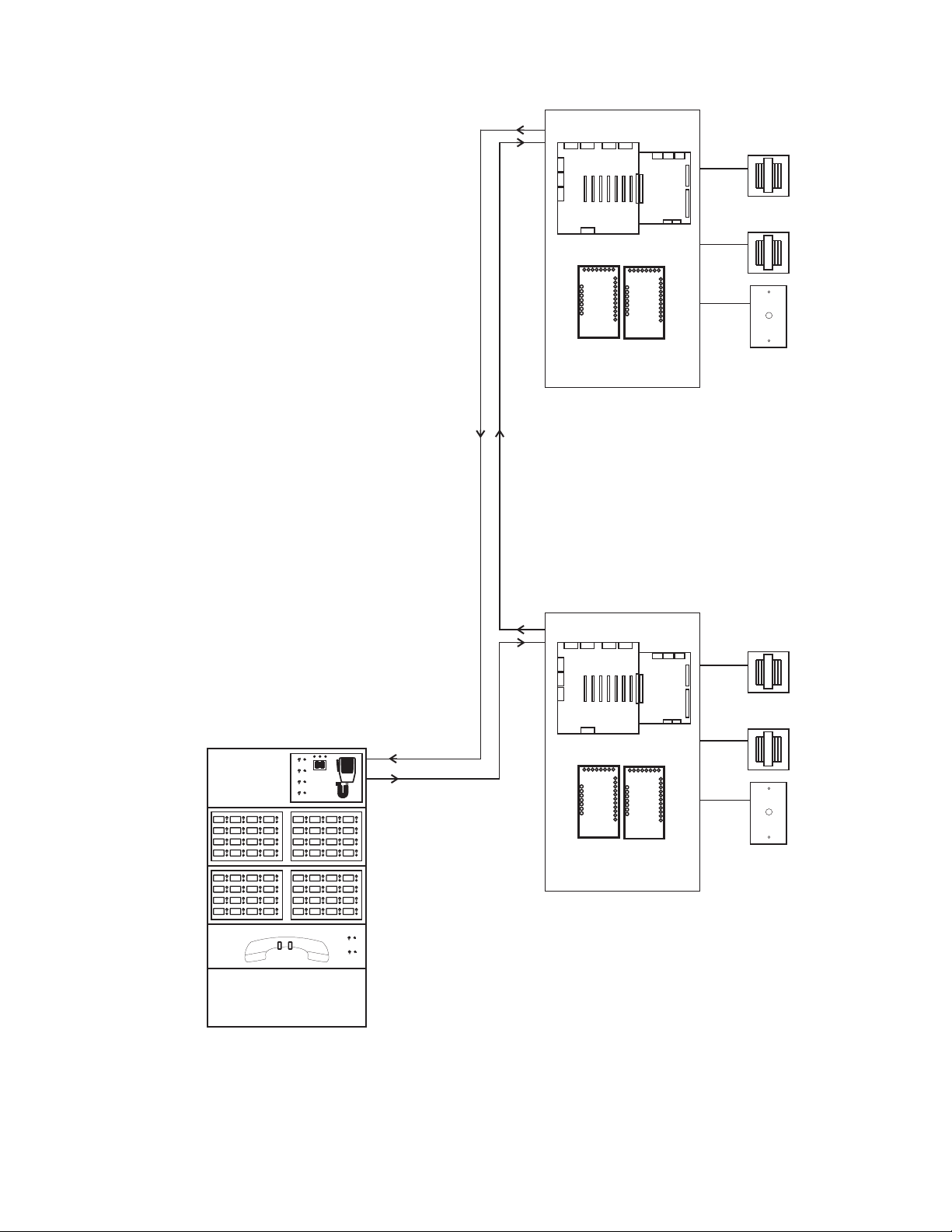
Distributed Panel Wiring
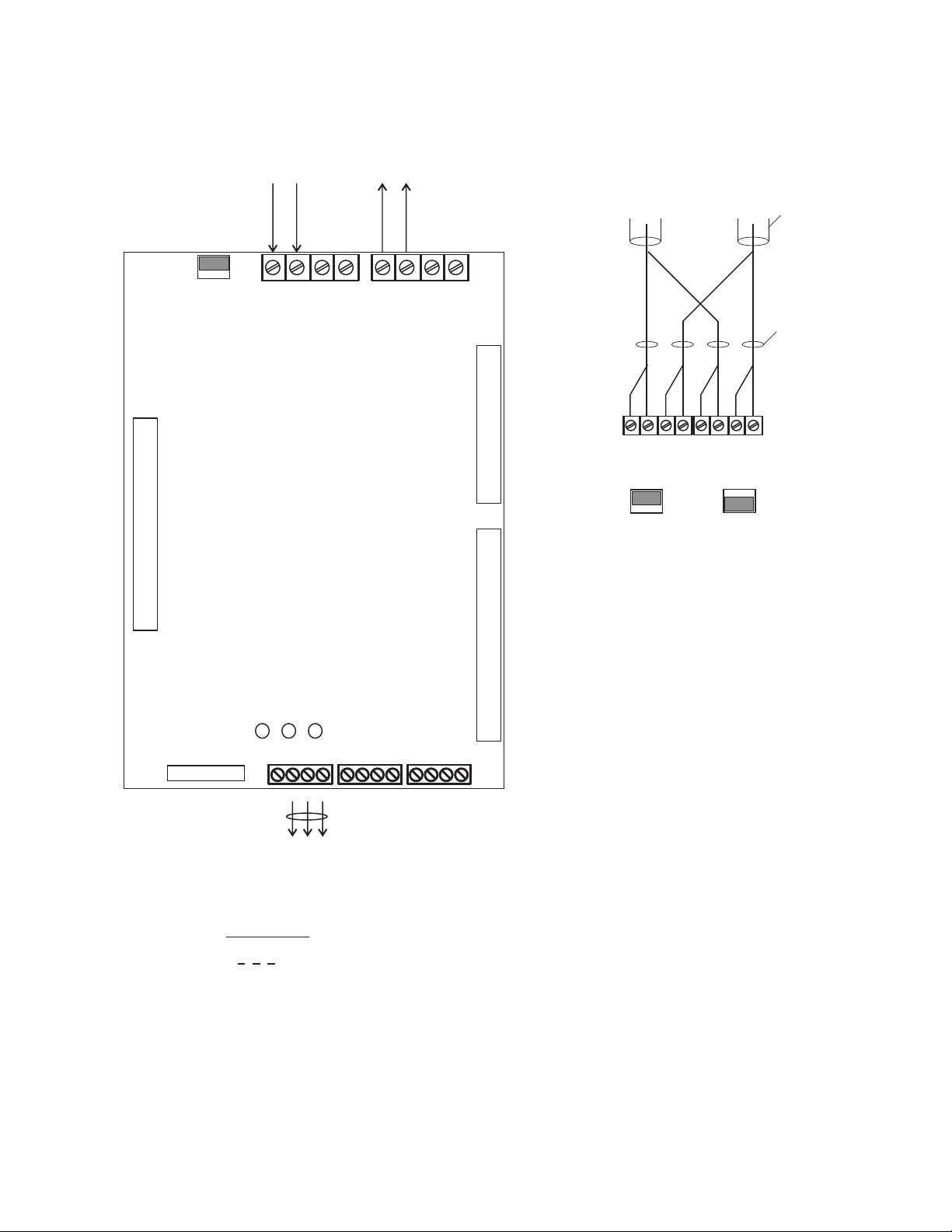
PVC 25(E) / 50(E) / 100(E) TROUBLE CODES
When a unit goes into a Trouble Condition, the Yellow LED wil remain on until the trouble is cleared. The Green
LED will flash a Code to indicate the type of Trouble Condition. There will be a pause between repeats of the
code. When multiple Trouble Conditions occur at the same time, the codes will add together.
The number of flashes and associated Trouble Condition are listed below.
Code Trouble Code Trouble
1 Power Failure 8 Amplifier Trouble
2 Open Speaker Circuit 16 Microphone Trouble
4 Shorted Speaker Circuit 32 Battery Trouble
6 External Trouble / Ground Fault
* 6 flashes typically indicates “External Trouble”, such as an PVC-RM. If LED 4 is on, the 6 flash indicates a ground fault.
If both a ground fault condition and an external trouble occur simultaneously, the fault codes will not combine for 12 flash.
Refer to Installation Instructions P/N PV-5001 for all amplifier specifications
Field wiring connections:
#6-32 wire clamp screw 14-18 AWG
#8-32 wire clamp screw 12-18 AWG
Horizontal wire entry terminal 18-26 AWG
Wire gauge determined by circuit load
LED 4
MIC
GAIN
LED 4
page 7
Supervised, Power Limited
Ground faults are indicated
at 10K impedance or less.
Supervised, Power Limited
Ground faults are indicated
at 10K impedance or less.
Note: Panels may be supplied with
transformers wired for 240 VAC for those
regions where this is required. Please
refer to Ratings section for Primary
Power differences.