Power Fist 8301251 User manual

User Manual
8301251V 1.5
Please read and understand all instructions before use.
Retain this manual for future reference.


3
For technical questions call: 1-800-665-8685
V 1.5 8301251
WARNING! Read and understand all instructions. Failure to follow all instructions listed below, may result in electric
shock, fire and/or serious personal injury. SAVE THESE INSTRUCTIONS
WORK AREA
1. Keep your work area clean and well lit. Cluttered benches and dark areas invite accidents.
2. Do not operate power tools in explosive atmospheres such as in the presence of flammable liquids,
gases, or dust. Power tools create sparks which may ignite the dust or fumes.
3. Keep bystanders, children and visitors away while operating a power tool. Distraction can cause you
to lose control.
Voltage 120V~60Hz
Rated Power 6.5A
No Load Speed: 16,000 RPM
Cutting Width 3-1/4"
Max. Cutting Depth 5/64"
Max. Rebating Depth 1/2"

6.5A Electric Planer
4For technical questions call: 1-800-665-8685
8301251 V 1.5
SPECIFIC SAFETY PRECAUTIONS
Rags, cloths, cord, string and the like should never be left around the work area. Remove all nails, screws and other
objects from the workpiece. Cutting into a nail or other foreign object will damage the blade and the tool. It can also
present a safety hazard.
1. Do not force the planer. Let the tool do the work at a reasonable speed. Overloading will occur if too
much pressure is applied and the motor slows resulting in inefficient planing and possible damage to
the planer motor.
2. Before using the tool on an actual workpiece, switch on and let it run for a while. Watch for vibration or
wobbling that could indicate poor installation or a poorly balanced blade.
3. Make sure the blade is not in contact with the workpiece when you switch the machine on. Wait until the
blades attain full speed before cutting.
4. Always change the two blades at the same time, otherwise the resulting imbalance will cause vibration and
shorten the blade and tool life.
5. Do not touch the external metal parts and blades after long working periods. They may be very hot.
6. Unplug the tool before making any adjustments and wait until the blades have come to a complete standstill.
7. During operation, hold the tool firmly with both hands and keep hands away from rotating parts. Do not
leave the machine running unattended. Operate the tool only when controlled by both hands.
8. Never stick your finger into the chip chute. Shavings may jam in the chute when cutting damp wood.
Clean out the chips with a stick but only when the tool has been unplugged.
9. Handle the blades very carefully. Be sure that the blade installation bolts are securely tightened
before operation.
PERSONAL SAFETY
1. Stay alert, watch what you are doing and use common sense when operating a power tool. Do not use
the tool while tired or under the influence of drugs, alcohol, or medication. A moment of inattention while
operating power tools may result in serious personal injury.
2. Dress properly. Do not wear loose clothing or jewelry. Contain long hair. Keep your hair, clothing, and gloves
away from the moving parts. Loose clothes, jewelry, and long hair can be caught in the moving parts.
3. Avoid accidental starting. Be sure switch is off before plugging in. Carrying tools with your finger on the
switch or plugging in tools that have the switch on will invite accidents.
4. Remove adjusting keys or wrenches before turning the tool on. A wrench or a key that is left attached to a
rotating part of the tool may result in personal injury.
5. Do not overreach. Keep proper footing and balance at all times. Proper footing and balance enable better
control of the tool in unexpected situations.
6. Use safety equipment. Always wear eye protection. Dust mask, non-skid safety shoes, hard hat, or hearing
protection must be used for appropriate conditions. Ordinary eye or sun glasses are NOT eye protection.
ELECTRICAL SAFETY
1. Avoid body contact with grounded surfaces such as pipes, radiators, ranges and refrigerators. There is an
increased risk of electric shock if your body is grounded.
2. Don’t expose power tools to rain or wet conditions. Water entering a power tool will increase the risk of
electric shock.
3. Do not abuse the cord. Never use the cord to carry the tool or pull the plug from an outlet. Keep the cord
away from heat, oil, sharp edges or moving parts. Replace the damaged cords immediately if you found one.
The damaged cords will increase the risk of electric shock.
4. When operating a power tool outside, use an outdoor extension cord which marked “W-A” or “W”. These
cords are rated for outdoor use , so it can reduce the risk of electric shock.

6.5A Electric Planer
5
For technical questions call: 1-800-665-8685
8301251V 1.5
1. Use clamps or other practical way to secure and support the work piece to a stable platform. Holding the
work piece by hand or against your body is unstable and may lead to loss of control.
2. Do not force tool. Use the correct tool for your application. The correct tool will do the job better and safer at
the rate for which it is designed.
3. Do not use tool if the switch can not turn it on or off. Any tool that cannot be controlled with the switch is
dangerous and must be repaired before use.
4. Disconnect the plug from the power source before making any adjustment, changing accessories, or storing
the tool. Such preventive safety measures can reduce the risk of starting the tool accidentally.
5. Store idle tools out of reach of children and other untrained persons. Tools are dangerous in the hands of
untrained users.
6. Maintain tools with care. Keep the cutting tools sharp and clean. Properly maintained tools with sharp
cutting edges are less likely to bind and are easier to control.
7. Check for misalignment or binding of moving parts, breakage of parts and any other condition that may
affect the tools operation. If damaged, have the tool serviced before using. Many accidents are caused by
poorly maintained tools.
8. Use only accessories that are recommended by the manufacturer for your model. Accessories that may be
suitable for one tool, may become hazardous when used on another tool.
1. Tool service must be performed only by qualified repair personnel. Service or maintenance performed by
unqualified personnel could result in a risk of injury.
2. When servicing a tool, use only identical replacement parts. Follow instructions in the maintenance section
of this manual. Use of unauthorized parts or failure to follow maintenance instructions may create a risk of
electric shock or injury.

6.5A Electric Planer
6For technical questions call: 1-800-665-8685
8301251 V 1.5
1. Carefully remove the parts and accessories from the box.
2. Make sure that all items listed in the parts lists are included.
3. Inspect the parts carefully to make sure no breakage or damage occurred during shipping.
4. Do not discard the packaging material until you have carefully inspected and satisfactorily operated the tool.
WARNING! If any part is missing, do not operate the tool until the missing parts are replaced. Failure to do so
could result in serious personal injury.
This planer has been designed for professional planing applications. Please refer to the illustration below to
familiarize yourself with the major components of this tool before using it.
# Description
1 Rear Handle
2 Lock-off Button
3 Trigger Switch
4 Chip Extraction Tube Button
5 Auxiliary Handle/Depth Adjustment Knob
6 Depth Scale
7 “T”Guide Fixing Screw
8 “T” Guide Slot
9 “L”Depth Guide Fixing Screw
10 V-shaped Groove
11 Spring Cover
12 Blade Fixing Screw
13 Planing Blade
14 Rear Base
15 Auto-retracting Foot
Description Quantity
Spanner 1
Carbon brush 1 pair
“T” guide 1
“L” guide 1
Dust bag 1

6.5A Electric Planer
7
For technical questions call: 1-800-665-8685
8301251V 1.5
CAUTION! Always ensure that the tool is switched off and unplugged from power supply before assembly or
making any adjustments.
CHANGING BLADES
Warning! Blades are sharp, use extreme caution when replacing them. This tool is fitted with two blades on the
blade barrel. Each blade has two sharpened edges. Therefore, you can reverse the blade when one edge has
become dull. Do not attempt to sharpen blades. If the blades become dull, reverse them or replace them with
new ones. Always replace or reverse blades in pairs.
1. Secure the planer in an upside down position.
2. Unscrew the three clamping screws with the spanner supplied. Take care not to over loosen the screws, only
loosen the screws enough so that the blade can be pushed out. This will aid with aligning new blades.
3. Push and slide the planer blade out from the blade barrel with a screwdriver while depressing the spring
cover at side.
Note:
Pay attention to the orientation of the blade edge when removing a blade so that the new blade
will be mounted correctly.
Note:
When installing blades, first clean out all chips or foreign matter adhering to the blade barrel and the blade
themselves. Use blades of the same dimensions and weight, or the barrel will oscillate and vibrate causing
poor planing action and possibly a machine breakdown.
4. Turn over the planer blade or replace it if required. Depress the spring cover and insert the blade from the
spring cover side into the blade holding slot until it locates centrally against the blade barrel.
5. Retighten the clamping screws.
6. Repeat for the second blade.
Note:
The planning surface will end up rough and uneven unless the blades are set properly and securely.
The blades must be mounted so that the cutting edge is absolutely level.
i.e. Parallel to the surface of the rear base.
FITTING THE DUST COLLECTION BAG
This tool has a dust extraction outlet and comes with a dust collection bag. Ensure bag is attached before each use.
CHANGING DIRECTION OF DUST EXTRACTION
The chip extraction can be directed at either side of the tool. To change its direction:
1. Depress the chip extraction tube button.
2. Hold the other end of the tube and pull it out.
3. Depress the chip extraction tube button and insert the tube from another side of the tool until the button
springs back to its original position and lock the tube in place.
Note:
There is a protruding tab on the tube, the tube can be inserted into the tool only when the tab is aligned with
the groove on the tool.
ADJUSTING THE DEPTH OF PLANING
The cutting depth of the tool can be adjusted by rotating the depth adjustment knob from 0 to 5/64" as required for
each pass. The reading of the depth scale (pointed by an arrow on the handle) indicates the depth of cut. The scale
is calibrated to a precision of 0.05 mm.
Note:
for accurate planing, make a trial cut on scrap material first before carrying out operation.

6.5A Electric Planer
8For technical questions call: 1-800-665-8685
8301251 V 1.5
SWITCHING ON/OFF
Caution! Ensure that the tool is in good condition.
1. Depress the lock-off button and then squeeze the on/off switch to start the tool.
2. Release the trigger switch to turn off the tool.
PLANING
1. Choose desired cut depth before operation.
2. It is desirable to select a shallow cutting depth and repeat the cutting process several times until
the desired depth is achieved.
3. Where possible, clamp the workpiece to the bench.
4. Rest the front base flat on the workpiece surface without the blades making any contact with the
workpiece. Apply some pressure on the tool through auxiliary handle so that the front base of the
tool is flat against the workpiece.
5. Switch on the tool and allow it to reach its full speed.
6. Hold the planer firmly with both hands and move the tool gently forward
7. When the tool is close to the finishing line, apply downward pressure onto the rear handle to keep the rear
base flat on the workpiece. Push the planer beyond the edge of the workpiece without tilting it downwards.
8. The rate of planing and the depth of cut determine the quality of the finish. For rough cutting, you can
increase the depth of cut, however to achieve a good finish you will need to reduce the depth of cut and
advance the tool more slowly.
Note: Wait for the blade to come to a complete stop before setting the tool down.
Note: The tool has an auto-retracting foot on the rear base to prevent the blade from contacting bench
top when the tool is put down. During operation, the foot will automatically retract as it passes
through the edge of workpiece.
CHAMFERING
1. Three “V” grooves are located in the front base which allows you to chamfer the edges of the workpiece.
2. Place either “V” groove onto the edge of the workpiece and make a steady stroke.
USING THE “T” GUIDE
The “T” guide is used for precise straight cutting along edges and can be mounted to either the left or right side
of the planer.
1. Slide the “T” guide through its guide slot to desired position and fix it by tightened the fixing screw.
2. Make sure the flat surface of “T” guide is kept tight against the edge of the workpiece while making your cut.

6.5A Electric Planer
9
For technical questions call: 1-800-665-8685
8301251V 1.5
REBATING
The “L” depth guide is used in conjunction with the “T” guide for rebating applications. The depth of rebating is
determined by the depth of cut and the number of passes made along the workpiece. The maximum rebate depth is
1/2" made in several passes up to 5/64" each time. The maximum width of rebate cut is 3-1/4" and is determined by
the setting of “T” guide.
1. Fit the “L” guide and the “T” guide to the planer on opposite sides of the tool.
2. Adjust the “T” guide according to the required cutting width and tighten the fixing screw.
3. Set the tool on a flat surface with the rear base flat with the surface, adjust the “L” guide so that the distance
between the bottom surface of the “L” guide and the flat surface equals to the desired rebating depth, tighten
the fixing screw of “L” guide.
4. Set the cutting depth adjustment knob to a suitable depth.
5. Carry out the planning with the flat surface of “T” guide kept tight against the edge of workpiece. Repeat
cutting until the bottom surface of “L” guide is level with the surface of workpiece.
WARNING! If any of the following events occur during normal operation, the power supply should be shut off at once and
tool thoroughly inspected by a qualified person and repaired if necessary:
1. The rotating parts get stuck or speed drops abnormally low.
2. The tool shakes abnormally accompanied by some unusual noise.
3. The motor housing gets abnormally hot.
4. Heavy sparks occur around the motor area.
WARNING! Preventive maintenance performed by unauthorized personnel may result in misplacing of internal
wires and components which could cause serious hazard.Be sure that the tool is switched off and unplugged before
attempting to perform inspection or maintenance. Regularly clean the tool’s air vents with compressed dry air.
Do not attempt to clean by inserting pointed objects through openings. Certain cleaning agents and solvents may
damage plastic parts. Some of these are: gasoline, carbon tetrachloride, chlorinated cleaning solvents, ammonia
and household detergents that contain ammonia. To ensure safe use and maximize service life of your tool, following
instructions should be observed:
1. Regularly inspect all mounting screws and ensure that they are properly tightened.
2. Regularly clean the air vents of the tool.
3. Check and replace carbon brushes when necessary.
REPLACING CARBON BRUSHES
1. Using the parts list included, locate the carbon brushes. Remove the brush holder caps with a
screwdriver and inspect the carbon brushes. Replace them when they are worn up to about one third.
2. Take the old brush out and install new brushes. Remove all of the brushes at once. Make sure the
brush slides freely within the brush housing.
3. Run the motor for 15 minutes without load to shape the brushes, so that they are properly aligned
with the commutator.
6.5A Electric Planer
10 For technical questions call: 1-800-665-8685
8301251 V 1.5
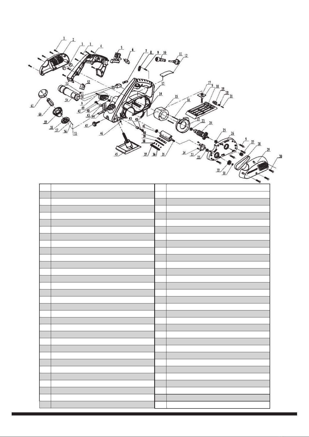
# Description
1 Philips Pan Head Self-tapping Screw (120)
2 Side Cover
3 Brush Rocker Presser Foot
4 Grip housing
5 Switch
6 Capacitor
7 Carbon Brush
8 Cable Hold-down Plate
9 Philips Pan Head Self-tapping Screw (4)
10 Cable Sleeve
11 Plug
12 Nameplate
13 Housing
14 Housing Chock
15 Stator
16 Philips Pan Head Self-tapping Screw (12)
17 Baffle
18 Rear Base Board
19 Rubber Foot
20 Spring For Rubber Foot
21 Fixing Pin
22 Fan Shroud
23 Bearing 627
24 Rotor
25 Bearing 6000
26 Middle Cover
27 Small Belt Pulley
28 Belt
29 Belt Cover
30 Philips Pan Head Screw M4X21 (3)
31 Screw M8
# Description
32 Big Belt Pulley
33 Cover For Bearing 6000
34 Philips Pan Head Screw M4X10
35 Axle Body
36 Pressure Bar
37 Socket Head Screw M 5x6
38 Hexagon Bolt M5x6
39 Blade
40 Blade Base
41 Bearing 608
42 Depth Guide Fixing Knob
43 Extended Cover For Knob
44 Depth Guide
45 Front Base Board
46 Hexagon Nut MB
47 Knob for “T” Bar
48 Spring for Baffle
49 Baffle
50 Brush Cover
51 Brush Box
52 Dust Outlet Knob
53 Spring for Dust Outlet
54 Dust Outlet
55 Small Spring
56 Small Steel Ball
57 Small Bronze Cover
58 Scale Plate
59 Hand Wheel Cover
60 Adjust Screw M10x2.5
61 Depth knob


Table of contents


