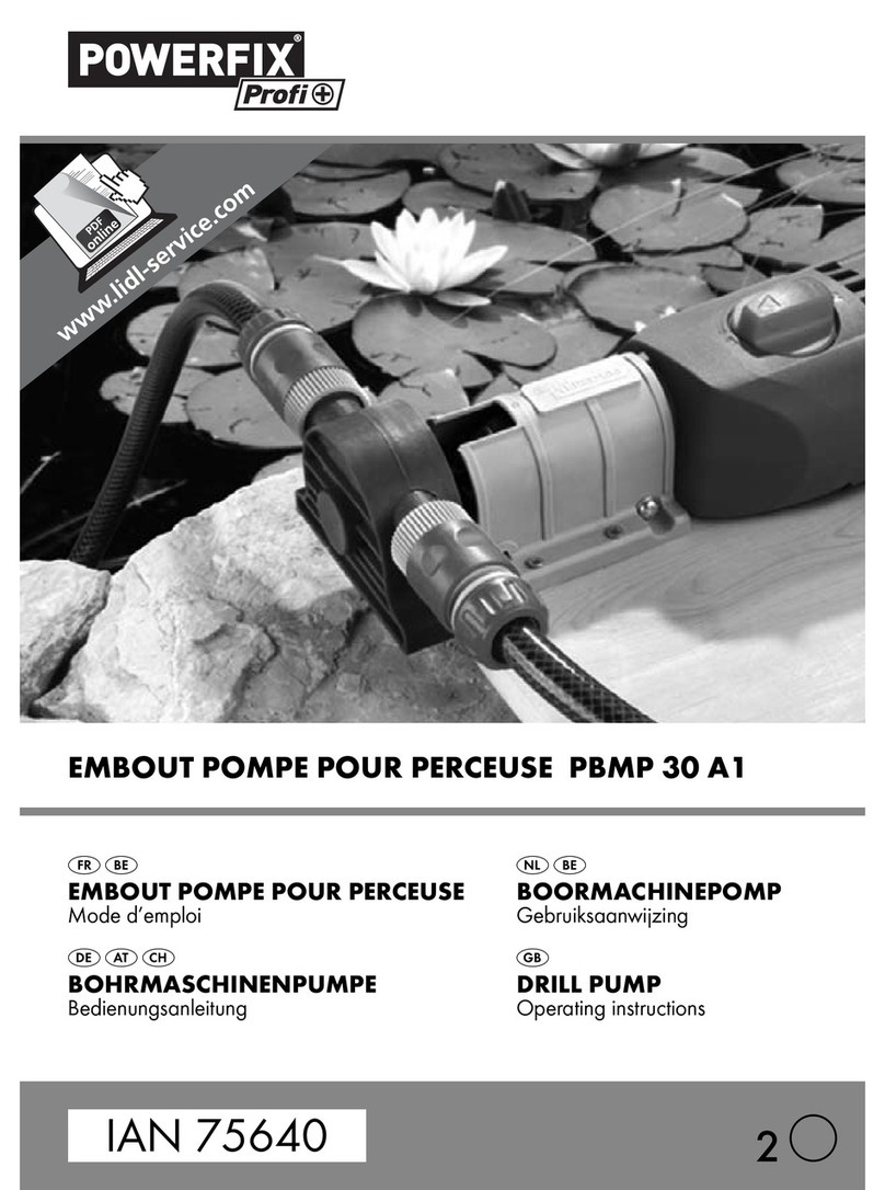
Powerfix PBMP 30 A1 User manual

DRILL PUMP PBMP 30 A1
DRILL PUMP
Operating instructions
4
IAN 75640
POMPA NA WIERTARKĘ
Instrukcja obsługi
FÚRÓGÉPSZIVATTYÚ
Használati utasítás ČRPALKA ZA VRTALNIK
Navodila za uporabo
PUMPA POHÁNĚNÁ VRTAČKOU
Návod k obsluze ČERPADLO K VŔTAČKE
Návod na obsluhu
BOHRMASCHINENPUMPE
Bedienungsanleitung

GB Operating instructions Page 1
PL Instrukcja obsługi Strona 11
HU Használati utasítás Oldal 21
SI Navodila za uporabo Stran 31
CZ Návod k obsluze Strana 41
SK Návod na obsluhu Strana 51
DE / AT / CH Bedienungsanleitung Seite 61
Before reading, unfold the page containing the illustrations and familiarise
yourself with all functions of the device.
Przed przeczytaniem proszę rozłożyć stronę z ilustracjami, a następnie
proszę zapoznać się z wszystkimi funkcjami urządzenia.
Olvasás előtt kattintson az ábrát tartalmazó oldalra és végezetül ismerje meg
a készülék mindegyik funkcióját.
Pred branjem odprite stran s slikami in se nato seznanite z vsemi funkcijami
naprave.
Před čtením si otevřete stranu s obrázky a potom se seznamte se všemi
funkcemi přístroje.
Pred čítaním si odklopte stranu s obrázkami a potom sa oboznámte so všet-
kými funkciami prístroja.
Klappen Sie vor dem Lesen die Seite mit den Abbildungen aus und machen
Sie sich anschließend mit allen Funktionen des Gerätes vertraut.

A
B

- 1 -
CONTENT PAGE
Introduction 2
Safety instructions 2
Intended Usage 3
Technical Data 3
Items supplied 4
Overview of the appliance 4
Assembly material required 4
Assembly and connection 5
Disassembly of the drive shaft 7
Utilisation 8
Cleaning and care 8
Disposal 9
Declaration of conformity 9
Importer 9
Warranty and Service 10
IB_75640_PBMP30A1_LB4.qxd 06.06.2012 12:13 Uhr Seite 1

- 2 -
Introduction
Congratulations!
With your purchase you have decided in favour of a quality product. Familiarise
yourself with the product before taking it into use. To do this, read the following
operating instructions attentively. Use the product only as described and only
for the specified areas of application. Retain these instructions for future refe-
rence. In addition, pass these documents on, together with the product, to any
future owner.
Safety instructions
To avoid the risk of accidents and damage to the
appliance:
• Operate the pump ONLY when it is secured by the supplied mounting
against jolting, twisting and canting.
• Check the pump for a faultfree condition before ever taking it into use.
The pump may not be used if it shows signs of damage.
The drive shaft of the pump does not allow itself to be turned by hand.
This does not indicate that the pump is defective.
• Use only hoses certified as being able to withstand a pressure of at least
3 bars (44 psi).
• Check the plug-in connectors on the hoses for firm seating.
• Take steps to ensure that the fluid being pumped cannot come into contact
with the electric drill during pumping. Should it nonetheless occur, imme-
diately remove the power plug.
• Avoid the intake of coarse dirt, otherwise the pump could be damaged.
If needs be, use a filter on the suction hose.
IB_75640_PBMP30A1_LB4.qxd 06.06.2012 12:13 Uhr Seite 2

- 3 -
• This appliance is not intended for use by children or other individuals whose
physical, sensorial or intellectual abilities prevent safe usage of the appli-
ance should they not receive support or supervision in the correct operati-
on of the appliance. Children should be supervised to ensure that they do
not play with the appliance.
Intended Usage
This pump is intended for ...
– standard commercial right/left rotating electric drills with a 43 mm Euro-
spindle and a gear-wheel rim chuck/quick-release chuck or drill chuck
with SDS fitting, up to rotation speed of 3400 rpm,
– the pumping of cold or up to 40°C warm fluids, such as non-potable or
dirty water from fish tanks or ponds.
This pump is NNOOTTintended for ...
– the pumping of flammable, explosive, poisonous or caustic liquids or
foodstuffs.
– for industrial or commercial applications.
Technical Data
Capacity: max. 2,4 m3/h
Hose connection: 3/4” (19 mm)
Pressure: max. 3 bar
Delivery height: max. 30 m
Suction height: max. 3 m
Temperature of the fluid being pumped: max. 40°C
Dry run time: max. 12 seconds
Rotation speed: max. 3400 rpm
IB_75640_PBMP30A1_LB4.qxd 06.06.2012 12:13 Uhr Seite 3

- 4 -
Items supplied
- Pump
- Short drive shaft
- Long drive shaft
- Clamp fixing
- Mounting
- Open-ended spanner
- Storage box for the drive shafts and open-ended spanner
- This operating manual
Overview of the appliance
Figure A:
qPump
wDrive shaft of the pump
eShort drive shaft (suitable for gear-wheel/quick-release chuck)
rLong drive shaft (suitable for a drill chuck with SDS fitting)
tClamp fastening
yMounting
Figure B:
uElectric drill (not supplied)
iRecess for chuck key
oConnection for suction hose
aConnection for pressure hose
Assembly material required
- Philips-type screwdriver
- Flat-headed screwdriver
- Open-ended spanner (supplied)
IB_75640_PBMP30A1_LB4.qxd 06.06.2012 12:13 Uhr Seite 4

- 5 -
Assembly and connection
Assemble the mounting ywith the clamp fastening tonto a work surface,
as shown in figure B.
Alternatively, the mounting ycan also be secured to a work surface
with screws (assembly material not supplied).
When using a gear-wheel chuck and the short drive
shaft e...
Screw the short drive shaft eonto the drive shaft wof the pump q.
Insert the electric drill uwith the chuck into the mounting y.
Now push the pump qonto the mounting yso that the drive shaft e
projects into the chuck and the pins of the mounting yare located in the
reception holes on the pump q.
Now tighten the chuck with the chuck key through the recess iso firmly
that the pump qcan no longer release itself from the mounting y.
Tighten the cross-headed screw on the mounting yfirmly, so that the drill
ucannot jolt around.
Attach the suction hose to the connection oand the pressure hose to the
connection a. Pay heed to the direction of flow detailed on the
pump q.
When using a quick-release chuck and the short drive
shaft e...
Secure the short drive shaft einto the chuck.
Insert the electric drill u, with the pre-assembled drive shaft ein the
chuck, into the mounting y.
Securely tighten the cross-head screw on the mounting yso that the drill u
is being firmly held.
IB_75640_PBMP30A1_LB4.qxd 06.06.2012 12:13 Uhr Seite 5

- 6 -
Now push the pump qonto the mounting yso that the drive shaft e
projects into the thread of the drive shaft w, and the pins of the mounting
yare located in the reception holes on the pump q.
Let the drill ustart to run in a clockwise rotation and at low revolutions
and then guide the pump qstraight onto the drive shaft e. The drive
shaft eis thereby secured to the pump q.
Attach the suction hose to the connection oand the pressure hose to the
connection a. Pay heed to the direction of flow detailed on the
pump q.
When using a chuck with SDS fitting and the long drive
shaft r...
Attach the long drive shaft rinto the chuck.
Insert the electric drill u, with the pre-assembled drive shaft rin the
chuck, into the mounting y.
Tighten the cross-headed screw on the mounting yfirmly, so that the drill u
cannot jolt around.
Now push the pump qonto the mounting yso that the drive shaft r
projects into the thread of the drive shaft wand the pins of the mounting
yare located in the reception holes on the pump q.
Allow the electric drill uto run with a clockwise rotation and low revoluti-
ons and guide the pump qstraight on to the drive shaft r. With this the
drive shaft rwill be fixated onto the pump q.
Attach the suction hose to the connection oand the pressure hose to the
connection a. Pay heed to the direction of flow detailed on the
pump q.
IB_75640_PBMP30A1_LB4.qxd 06.06.2012 12:13 Uhr Seite 6

- 7 -
Disassembly of the drive shaft
Disassembly of the short drive shaft e
Wheel rim chuck
Open the chuck with the chuck key through the recess iand then remove
the pump qfrom the mounting y.
Unscrew the short drive shaft eby using a cross-headed screwdriver and
the open-ended spanner from the pump q.
Quick-release chuck
Using the open-ended spanner through the recess i, counter screw the
drive shaft wof the pump q.
Allow the electric drill uto run with an anti-clockwise rotation and low re-
volutions. The drive shaft eis thereby released from the pump q.
Remove the pump qfrom the mounting y.
Remove the drive shaft efrom the chuck.
Disassembly of the long drive shaft r
Chuck with SDS fitting
Using the open-ended spanner through the recess, icounter screw the
drive shaft wof the pump q.
Allow the electric drill uto run with an anti-clockwise rotation and low
revolutions. With this the drive shaft rwill be released from the pump q.
Remove the pump qfrom the mounting y.
Remove the drive shaft rfrom the chuck.
IB_75640_PBMP30A1_LB4.qxd 06.06.2012 12:13 Uhr Seite 7

- 8 -
Utilisation
Attention!
The pump is self priming. If the pump qdoes not start to suck up within 12
seconds, turn the drill uoff immediately to avoid seizure. For this same rea-
son, do not allow the pump qto commence suction if the pressure hose on
the discharge side is closed.
Place the open end of the suction hose into the liquid that is to be pumped.
The suction hose may not be longer than 3 m. Ensure that the suction hose
does not pull in air.
If the pump qdoes not commence suction, fill the hose with some water
and then lift it so that the liquid runs before the pump.
Allow the drill u, now the pump q, to start-up – but not without supervision,
so that you can react quickly in the event of danger. Absolutely ensure
that the electric drill uis rotating to the right, as with normal drilling.
Should the rotation speed of the electric drill ube adjustable, you can
use this to regulate the discharge flow.
Turn the drill off immediately after the container is empty.
Cleaning and care
Clean the pump qwith a dry or lightly moistened cloth only. To avoid damage
to the plastic surfaces, do not use solvents or abrasive cleaning agents.
The pump is maintenance free.
IB_75640_PBMP30A1_LB4.qxd 06.06.2012 12:13 Uhr Seite 8

- 9 -
Disposal
Do not dispose of the appliance in your normal domestic waste.
Dispose of the appliance through an approved disposal centre or at your
community waste facility. Observe the currently applicable regulations. In
case of doubt, please contact your waste disposal centre.
Dispose of all packaging materials in an environmentally friendly
manner.
Declaration of conformity
We, Kompernaß Handelsgesellschaft GmbH, Burgstraße 21, D-44867 Bochum
declare under our sole responsibility that this product complies with all requi-
rements of the Machinery Directive: 2006/42/EC.
Type/Appliance Designation: Powerfix Profi Plus Drill Pump PBMP 30 A1
Serial number: IAN 75640
Year of manufacture: 05/2012
Bochum, dated 10.05.2012
Semi Uguzlu, Quality Manager
Importer
KOMPERNASS GMBH
BURGSTRASSE 21
44867 BOCHUM, GERMANY
www.kompernass.com
IB_75640_PBMP30A1_LB4.qxd 06.06.2012 12:14 Uhr Seite 9

- 10 -
Warranty and Service
The warranty for this appliance is for 3 years from the date of purchase. The
appliance has been manufactured with care and meticulously examined be-
fore delivery. Please retain your receipt as proof of purchase. In the event of
a warranty claim, please make contact by telephone with our Service Depart-
ment. Only in this way can a post-free despatch for your goods be assured.
The warranty covers only claims for material and manufacturing defects, but
not for transport damage, for wearing parts or for damage to fragile compo-
nents, e.g. buttons or batteries. This product is for private use only and is not
intended for commercial use. The warranty is void in the case of abusive and
improper handling, use of force and internal tampering not carried out by our
authorized service branch. Your statutory rights are not restricted in any way
by this warranty.
The warranty period will not be extended by repairs made under warranty.
This applies also to replaced and repaired parts. Any damage and defects
extant on purchase must be reported immediately after unpacking the appli-
ance, at the latest, two days after the purchase date. Repairs made after the
expiration of the warranty period are subject to payment.
Service Great Britain
Tel.: 0871 5000 720 (£ 0.10/Min.)
E-Mail: k[email protected]
Service Ireland
Tel.: 1890 930 034
(0,08 EUR/Min., (peak))
(0,06 EUR/Min., (off peak))
E-Mail: k[email protected]
IAN 75640
IAN 75640
IB_75640_PBMP30A1_LB4.qxd 06.06.2012 12:14 Uhr Seite 10

- 11 -
SPIS TREČCI STRONA
Wstęp 12
Wskazówki dotyczące bezpieczeństwa 12
Zastosowanie zgodnie z przeznaczeniem 13
Dane techniczne 13
Zakres dostawy 14
Przegląd urządzenia 14
Niezbędne narzędzia do montażu 14
Montaż i podłączanie 15
Demontaż trzonka napędowego 17
Użytkowanie 18
Czyszczenie i konserwacja 18
Utylizacja 19
Deklaracja zgodności 19
Importer 19
Gwarancja i serwis 20
IB_75640_PBMP30A1_LB4.qxd 06.06.2012 12:14 Uhr Seite 11

- 12 -
Wstęp
Gratulacje!
Dziękujemy ci za zakup naszego produktu o wysokiej jakości. Przed przy-
stąpieniem do pierwszego uruchomienia zapoznaj się z obsługą produktu.
W tym celu przeczytaj niniejszą instrukcję obsługi. Używaj produkt zgodnie
z opisem i w podanych obszarach użytkowania. Instrukcję obsługi przecho-
wuj zawsze w bezpiecznym miejscu. W razie przekazania produktu następ-
nej osobie, nie zapomnij dołączyć również instrukcji obsługi.
Wskazówki dotyczące bezpieczeństwa
Jak uniknąć wypadku i uszkodzenia urządzenia:
• Używaj pompki tylko wtedy, gdy będzie ona zabezpieczona za pomocą
dołączonego uchwytu przed wypadnięciem, przekręceniem lub przekrzy-
wieniem.
• Przed każdym użyciem pompki sprawdź jej stan techniczny.
Nie używaj pompki, która uległa uszkodzeniu.
Wałkiem napędowym pompki nie da się obracać ręcznie.
Nie wskazuje to na uszkodzenie pompki.
• Używaj wyłącznie węży przystosowanych do ciśnienia minimalnego 3 bar.
• Sprawdź, czy złączki zostało prawidłowo podłączone do węży.
• Nie dopuść do przedostania się cieczy do wiertarki napędzającej pompkę.
Gdy jednak do tego dojdzie, natychmiast wyciągnij wtyczkę z gniazdka.
• Unikaj zasysania większych zanieczyszczeń, gdyż w przeciwnym razie
pompka mogłaby ulec uszkodzeniu. Ewentualnie zamontuj filtr na wężu
zasysającym.
• To urządzenie nie nadaje się do użytkowania przez dzieci ani osoby
o ograniczonej sprawności fizycznej, ruchowej lub umysłowej przebywające
bez nadzoru opiekuna. Nie można pozwolić dzieciom na zabawę
urządzeniem.
IB_75640_PBMP30A1_LB4.qxd 06.06.2012 12:14 Uhr Seite 12

- 13 -
Zastosowanie zgodnie z przeznaczeniem
Ta pompka jest przeznaczona do ...
– dostępne w sprzedaży wiertarki prawo-/lewoskrętne z szyjką wrzeciona
43 mm i uchwytem zębatym lub uchwytem wiertarskim SDS, o prędkości
obrotowej do 3400 obr./min.,
– pompowania zimnych lub ciepłych (do temp. 40°C) cieczy, takich jak
woda użytkowa lub ściekowa z akwariów lub oczek wodnych.
Ta pompka nniieejest przeznaczona do ...
– pompowania łatwopalnych, wybuchowych, trujących lub żrących cieczy
ani artykułów spożywczych.
– celów przemysłowych ani komercyjnych.
Dane techniczne
Wydatek: maks. 2,4 m3/h
Przyłącze węża: 3/4” (19 mm)
ciśnienie: maks. 3 bar
wysokość tłoczenia: maks. 30 m
wysokość zasysania: maks. 3 m
Temperatura cieczy: maks. 40°C
Czas pracy na sucho: maks. 12 sekund
Prędkość obrotowa: maks. 3400 obr./min.
IB_75640_PBMP30A1_LB4.qxd 06.06.2012 12:14 Uhr Seite 13

- 14 -
Zakres dostawy
- pompka
- trzonek napędowy krótki
- trzonek napędowy długi
- mocowanie zaciskowe
- uchwyt
- klucz szczękowy
- skrzynka do przechowywania trzonków i klucza szczękowego
- instrukcja obsługi
Przegląd urządzenia
Rysunek A:
qpompka
wwałek napędowy pompki
etrzonek napędowy krótki (do chwytów z wieńcem zębatym/szybkomocu-
jących)
rtrzonek napędowy długi (do uchwytu SDS)
tmocowanie zaciskowe
yuchwyt
Rysunek B:
uWiertarka (nie ma w zestawie)
iWycięcie na klucz do chwytu wiertarskiego
oPrzyłącze węża zasysającego
aPrzyłącze węża ciśnieniowego
Niezbędne narzędzia do montażu
- śrubokręt krzyżakowy
- śrubokręt rowkowy
- klucz szczękowy (dołączony do pompki)
IB_75640_PBMP30A1_LB4.qxd 06.06.2012 12:14 Uhr Seite 14

- 15 -
Montaż i podłączanie
Zamontuj uchwyt yz mocowaniem zaciskowym tw płytce roboczej,
jak pokazano na ilustracji B.
Uchwyt ymożesz również przykręcić śrubami do płytki roboczej
(śruby nie są dołączone do pompki).
W przypadku użycia chwytu z wieńcem zębatym i
krótkiego trzonka napędowego e...
Krótki trzonek napędowy eprzykręć na wałek napędowy wpompki q.
Wsuń wiertarkę uuchwytem wiertarskim w uchwyt y.
Następnie pompkę qwsuń na uchwyt yw taki sposób, by trzonek
napędowy ewszedł w uchwyt wiertarski, a trzpienie uchwytu y
weszły w otwory mocujące na pompce q.
Uchwyt wiertarski dokręć przez wycięcie idotąd, aż nie będzie można
odłączyć pompki qod uchwytu y.
Dokręć śrubę z łbem krzyżowym ytak, by wiertarka unie przewróciła się.
Podłącz wąż ssący do przyłącza oi wąż ciśnieniowy do przyłącza a.
Zwracaj przy tym uwagę na kierunek przepływu pokazany na
pompce q.
W przypadku użycia chwytu szybkomocującego i
krótkiego trzonka napędowego e...
Długi trzonek napędowy eprzymocuj do chwytu wiertarskiego.
Wiertarkę u, z zamocowanym w chwycie wiertarskim trzonkiem napędo-
wym e, wsuń w uchwyt y.
Dokręć śrubę z łbem krzyżowym w uchwycie ytak, by wiertarka usię
nie przewróciła.
IB_75640_PBMP30A1_LB4.qxd 06.06.2012 12:14 Uhr Seite 15

- 16 -
Pompkę qwsuń na uchwyt yw taki sposób, by trzonek napędowy e
wszedł w gwint wałka napędowego w, a trzpienie uchwytu yw otwory
mocujące na pompce q.
Włącz wiertarkę uustawioną na obracanie w prawo z niską prędkością
obrotową i równo wsuń pompkę qna trzonek napędowy e. Trzonek
napędowy ezamocuje się przez to w pompce q.
Podłącz wąż ssący do przyłącza oi wąż ciśnieniowy do przyłącza a.
Zwracaj przy tym uwagę na kierunek przepływu pokazany na
pompce q.
W przypadku użycia chwytu z mocowaniem SDS i
długiego trzonka napędowego r...
Długi trzonek napędowy rprzymocuj do uchwytu wiertarskiego.
Wiertarkę uwsuń założonym w uchwycie wiertarskim trzonkiem napę-
dowym rw uchwyt y.
Dokręć śrubę z łbem krzyżowym ytak, by wiertarka unie przewróciła się.
Pompkę qwsuń na uchwyt yw taki sposób, by trzonek napędowy r
wszedł w gwint wałka napędowego w, a trzpienie uchwytu yw otwory
mocujące na pompce q.
Włącz wiertarkę uustawioną na obracanie w prawo z niską prędkością
obrotową, a następnie wsuń pompkę qprosto na trzonek napędowy r.
Trzonek napędowy rw ten sposób zostanie przymocowany w pompce q.
Podłącz wąż ssący do przyłącza oi wąż ciśnieniowy do przyłącza a.
Zwracaj przy tym uwagę na kierunek przepływu pokazany na
pompce q.
IB_75640_PBMP30A1_LB4.qxd 06.06.2012 12:14 Uhr Seite 16

- 17 -
Demontaż trzonka napędowego
Demontaż krótszego trzonka napędowego e
Chwyt z wieńcem zębatym
Otwórz uchwyt wiertarski specjalnym kluczem przez wycięcie ii wyjmij
pompkę qz uchwytu y.
Za pomocą śrubokręta rowkowego lub klucza szczękowego odkręć trzonek
napędowy eod pompki q.
Chwyt szybkomocujący
Kluczem szczękowym zakontruj przez wycięcie iwałek napędowy w
pompki q.
Włącz wiertarkę uustawioną na obracanie w lewo z niską prędkością
obrotową. Trzonek napędowy ezamocuje się przez to w pompce q.
Wyjmij pompkę qz uchwytu y.
Wyjmij trzonek napędowy ez uchwytu wiertarskiego.
Demontaż długiego trzonka napędowego r
Chwyt z mocowaniem SDS
Kluczem szczękowym zakontruj przez wycięcie iwałek napędowy w
pompki q.
Włącz wiertarkę uustawioną na obracanie w lewo z niską prędkością
obrotową. Spowoduje to zwolnienie trzonka napędowego rod pompki q.
Wyjmij pompkę qz uchwytu y.
Wyjmij trzonek napędowy rz uchwytu wiertarskiego.
IB_75640_PBMP30A1_LB4.qxd 06.06.2012 12:14 Uhr Seite 17
Other manuals for PBMP 30 A1
2
This manual suits for next models
1
Table of contents
Languages:
Other Powerfix Water Pump manuals
Popular Water Pump manuals by other brands

Grundfos
Grundfos alpha2 l Installation and operating instructions

Wilo
Wilo Stratos PARA-C Installation and operating instructions

Lincoln
Lincoln Quicklub 223 user manual

Levitronix
Levitronix BPS-200 user manual

ubbink
ubbink AlgClear UV-C 2500 Operating instruction

Grundfos
Grundfos SL1.50 Installation and operating instructions