I
I
Model 180-18" Planer
I.
GENERAL
SET-UP
AND
ALIGNMENT
1.
RECEIYING
Uncrate
and
check
for
shipping
damage.
Clean
all
coated
and greased surfaces. Read instructions thoroughly.
Lo-
cate
all
lubrication points; adjustment; methods
of
drive
.
2.
MOUNTING
Mount
machine securely
to
solid foundation. Concrete
base mounting preferred. Locate
in
clean,
dry
and
well
vent.ilated building if p()ssible.
Motor
and
electrical con-
nections should be protected when not
in
operation
or
if
exposed to weather elements.
3.
EXHAUST
SYSTEM
Recommended
as
a must
if
efficient
production
operation
is
required.
Not
a necessity where limited amount
of
operation being performed
and
machine can be kept
clean
of
shavings.
4.
INSPECTION
The
above machine requires the minimum amount
of
attention
in
service. Periodic
or
regular
inspections
are
recommended to insure machine
is
in
proper
adjustment,
positive electrical connections; worn
or
loose
"Y"
belts
and
bearings heating
or
loose.
5.
BEFORE
OPERATING
Check motor nameplate
date
or
wiring
diagram
of
motor
and switch
for
proper
voltage
connection before
wiring
into line.
Run
motor without
load
to
check the connections
and direction
of
rotation. Always refer
to
motor name-
plate
for
rotation connections.
II.
LUBRICATION
1.
The
cutterhead
and
variable
speed
pulley
are mounted in
sealed bearings
and
do
not require
any
lubrication.
2.
GREASE
LUBRICATION
The
clutch,
table
and feed rollers are
equipped
with pres-
sure gun fittings and must be lubricated
regularly
every
twenty-five hours
of
operation with a
good
grade
High
Speed Boll Bearing grease. Also, the feed
drive
gears
should be surfaced greased with the same grease.
3.
OIL
LUBRICATION
The
surface fittings, bed ways, handwheel drive shaft
gears and thrust screws should be lubricated
regularly
every ten hours
of
operation with oil equivalent
to
SAE
10.
A light film
of
oil
on
the
table
when
not
in
use
will
prevent
rusting.
III.
OPERATING
ADJUSTMENTS
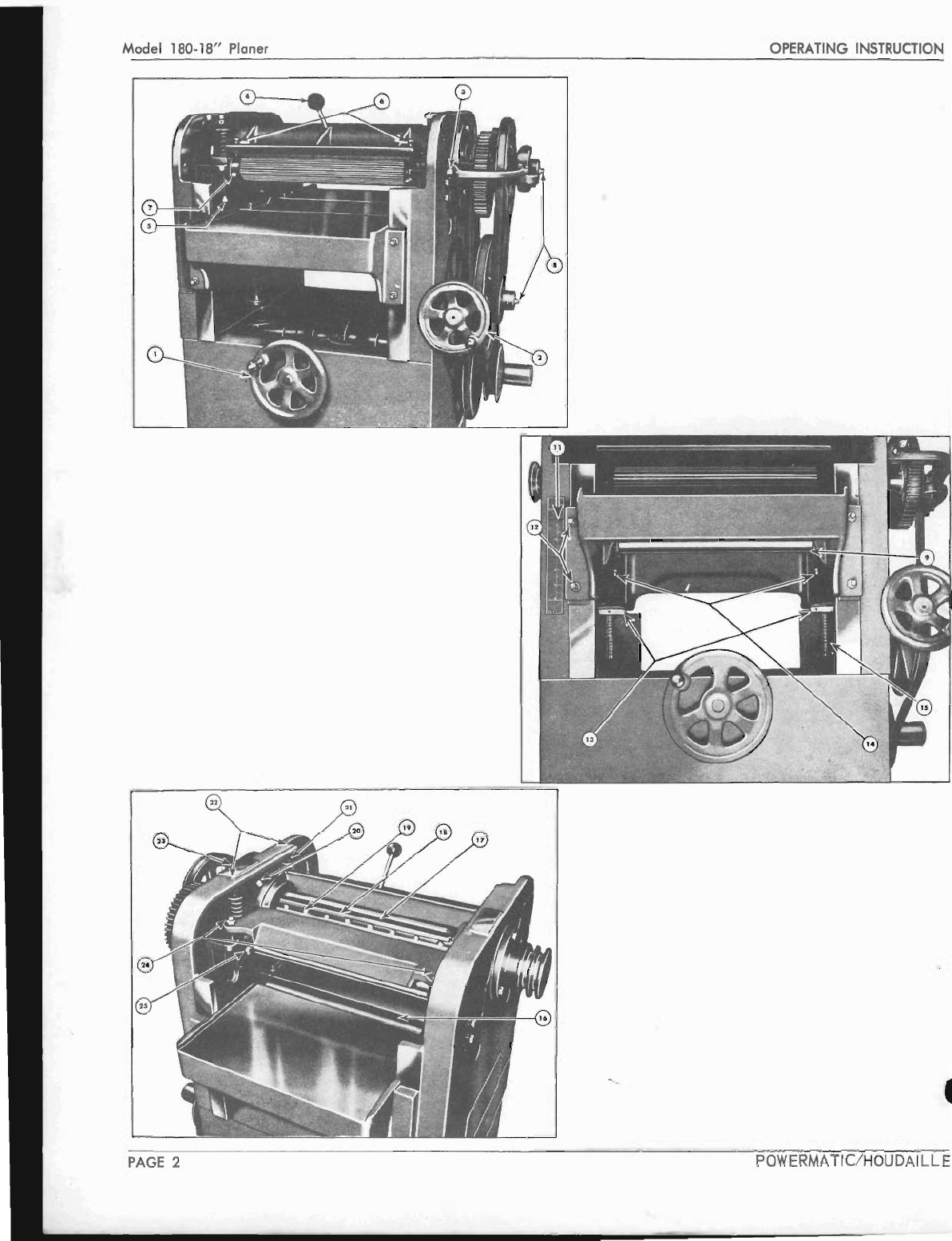
PLANER
BED:
The
planer bed mounts in the main frame panels
and
is
raised and lowered on acme screws mounted
in
thrust
bearings.
The
screws are operated through gears
by
a
large hondwheel (l ) on the front
of
the Planer.
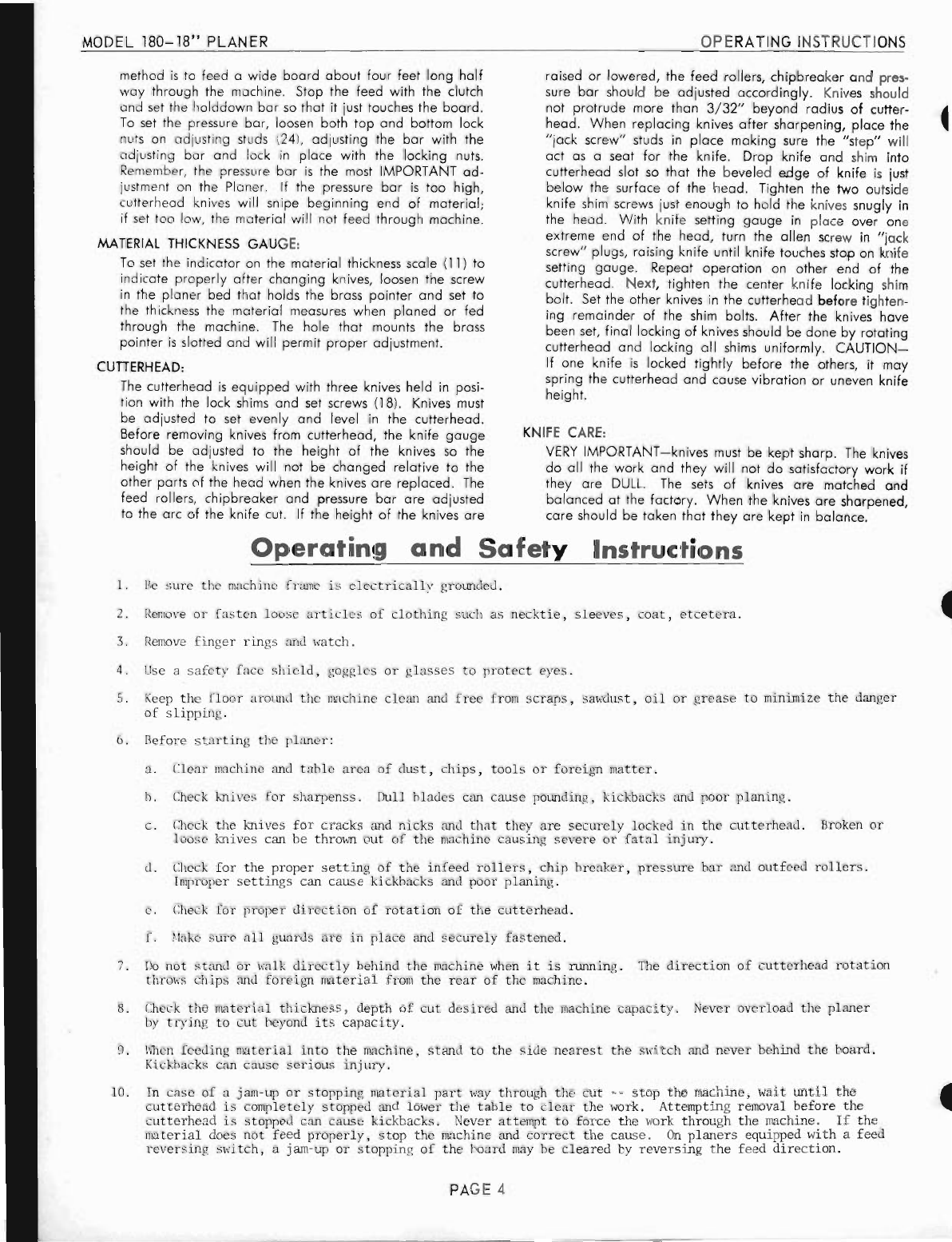
The
planer bed
is
held
rigid
between frames
by
shims on
each side
of
the bed
and
is
adjusted with
two
jack screws
(
12
) that can be tightened against the shims. These shims
should be adjusted
tight
enough to prevent rocking
or
moving when material
is
fed through the Planer but not
tight enough to prevent raising
or
lowering
of
the
table
.
If planer bed rocks when the machine
is
in operation, dips
will
appear
in the material being
planed
. The
planer
bed
POWERMATIC/HOUDAILLE
OPERATING
INSTRUCTIONS
must be level with the cutterhead. Check this
by
lowering
the bed
to
permit
placing
a small jack-screw
type
gauge
(
or
small square block) between the bed and the cutter-
head
at
the extreme
right
side
of
the bed.
Raise
bed with
handwheel (1) until the screw
gauge
or
block just touches
the cutterhead. Move the block
to
the
left
side
of
the
table
and
check under the cutterhead. If the bed
is
not .
level with the cutterhead, the bed can be raised or
lowered
by
loosening the set screw· in bed nut (13) and
turning
to
the
right
or
left
to
raise
or
lower the bed to the
proper
height-lock
the bed nut with the set screw.
PLANER
BED
IDLER
ROLLERS:
Adjusting screws (14)
for
planer
bed idler rollers are lo-
cated
directly
under the bearings. Adjust from .000 to
.
010"
above bed level
for
planing
smooth
or
dry
material,
.010"
to
.015"
for
medium rough
and
.
025"
to
.035"
for
rough sawed
or
green material. Keep rollers adjusted to
same height
at
each end.
When
rollers are set too high,
a snipe
or
bite
will
appear
at
the ends
of
planed
material.
If set too
low
feeding
will
be restricted due to friction
on
planer
bed.
(WITH
QUIK-SET
ADJUSTMENTS)
Planer bed rollers are adjusted
to
the
proper
height with
a quik-set
handle
mounted on the
right
side
of
the
planer
bed.
The
height
of
the rollers in relation to the bed sur-
face
is
indicated
by
a
graduated
dial
and
pointer on the
qUik-set handle. If
table
rollers
do
not correspond with
the height
indicator
scale, adjustments can be made' by
loosening the set screw (26) fig. 4 in the
roller
adjusting
arms. Set indicator pointer
at
zero on the
gauge
and
turn adjusting screws (27) until the bed rollers are level
with the
planer
bed.
To
plane rough lumber, set quik-set
indicator on
.030",
for
medium rough
.010"
to
.
015"
and
for
finished lumber
.000"
to
.010".
Set the rollers high
enough
so
that
the lumber
will
feed through the machine
without hesitation.
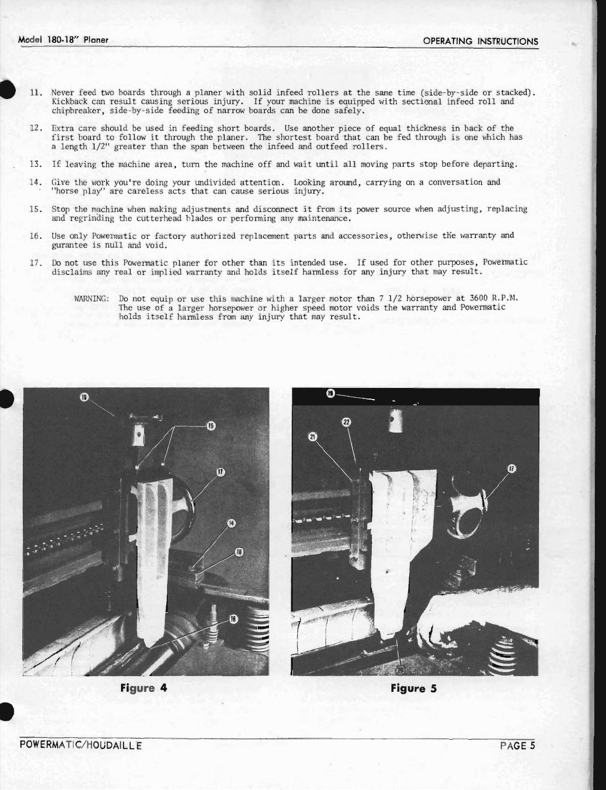
POWER
DRIYEN
FEED
ROLLS:
The
power
driven
corrugated
infeed
roller
(7)
and
smooth
outfeed
roller
(25) are
gear
driven through Y-belts
ar-
rangement from cutterhead shaft.
The
feed roller bearing
housings
are
floating
type
and
held against the feed roller
adjusting screws (14)
by
means
of
adjustable pressure
springs (22). The feed rollers should be adjusted
to
set
approximately
1/
16"
below
arc
of
the cutterhead knives.
A
gauge
or
block
may
be used to assure
proper
height.
To
set feed rolls, lower
planer
bed
about
3"
below
arc
of
cutterhead. Place
gauge
or
wooden
block directly under
cutterhead
and
turn head until one knife
is
down.
Raise
planer
bed until block
is
1/
16"
below
knife edge. Check
the
roller
to
see
that
each end
is
the same. Too much pres-
sure on infeed
corrugated
roller
will
leave markings on
material. Too little pressure
will
restrict feed.
CHIPBREAKER:
The
chipbreaker
is
a three piece
type
which mounts and
adjusts concentric with cutterhead.
The
chipbreaker
ad-
justing screws (6) should be adjusted
to
allow
chipbreaker
to
set
1/16"
below
level
of
infeed
corrugated
feed roller.
PRESSURE
BAR:
The pressure
bar
is
a three piece
type
which mounts
and
adjusts concentric with cutterhead. The pressure
bar
should be set equal
to
the arc
of
the cutterhead.
One
PAGE 3