PowerPlus Energy LiFe4838P User manual

Installation and
Operation Manual
Your complete installation guide for our LiFe4838P
battery, part of the LiFe Premium Series.
LiFe4838P

PowerPlus Energy Pty Ltd • LiFe4838P Installation and Operation Manual 19/10/2023 | V2.5 page 2 of 20
CONTENTS
5.3 Battery Connections . . . . . . . . . . . . . . . . . . . . . 10
5.3.1 Main DC Connections . . . . . . . . . . . . . . . . . 10
5.3.2 Case Earthing . . . . . . . . . . . . . . . . . . . . . 11
5.3.3 Battery Alarm Output . . . . . . . . . . . . . . . . . 11
6. BATTERY OPERATION . . . . . . . . . . . . . . . . . . . . . 13
6.1 Status LED . . . . . . . . . . . . . . . . . . . . . . . . . . 13
6.2 DC Circuit Breaker . . . . . . . . . . . . . . . . . . . . . . 13
6.2.1 Battery System Startup . . . . . . . . . . . . . . . . 14
6.2.2 Battery System Shutdown . . . . . . . . . . . . . . . 14
6.3 Charging and Discharging . . . . . . . . . . . . . . . . . . 14
6.3.1 Full Recharge Upon First Installation . . . . . . . . . . 14
6.3.2 Battery String Balancing . . . . . . . . . . . . . . . . 14
6.3.3 Over-Discharged Battery . . . . . . . . . . . . . . . 15
6.3.4 Primary Charging Source . . . . . . . . . . . . . . . 15
6.3.5 Secondary Charging Source . . . . . . . . . . . . . 15
6.3.6 PCS with SCS Example . . . . . . . . . . . . . . . . 15
6.3.7 Power Conversion Equipment (PCE) Settings . . . . . 15
6.4. Calibration to 100% . . . . . . . . . . . . . . . . . . . . . 15
6.5. SoC (State of Charge) Drift . . . . . . . . . . . . . . . . . . 15
7. TROUBLESHOOTING . . . . . . . . . . . . . . . . . . . . . . 16
7.1 Over-Discharged Battery Recovery . . . . . . . . . . . . . . 17
7.1.1 Soft Shutdown (2 ashes) . . . . . . . . . . . . . . . 17
7.1.2 BMS Threshold Soft Shutdown . . . . . . . . . . . . 17
7.1.3 Soft Shutdown Recovery . . . . . . . . . . . . . . . 17
7.1.4 Hard Shutdown (15 or 16 ashes) . . . . . . . . . . . 17
7.1.5 Hard Shutdown Recovery . . . . . . . . . . . . . . . 17
8. MAINTENANCE . . . . . . . . . . . . . . . . . . . . . . . . . 18
9. UPGRADING BATTERY CAPACITY . . . . . . . . . . . . . . . 18
10. CAPACITY TESTING THE BATTERY . . . . . . . . . . . . . . 19
11. COMPATIBLE INVERTERS . . . . . . . . . . . . . . . . . . . 19
12. END OF LIFE . . . . . . . . . . . . . . . . . . . . . . . . . . 20
13. WARRANTY . . . . . . . . . . . . . . . . . . . . . . . . . . 20
1. INTRODUCTION . . . . . . . . . . . . . . . . . . . . . . . . . . 3
2. GLOSSARY . . . . . . . . . . . . . . . . . . . . . . . . . . . . 3
3. SAFETY . . . . . . . . . . . . . . . . . . . . . . . . . . . . . . 4
3.1 Transportation . . . . . . . . . . . . . . . . . . . . . . . . . 4
3.2 Basic Safety . . . . . . . . . . . . . . . . . . . . . . . . . . 4
3.3 Handling . . . . . . . . . . . . . . . . . . . . . . . . . . . . 5
3.4 Storage of the Battery . . . . . . . . . . . . . . . . . . . . . 5
3.5 Life Support . . . . . . . . . . . . . . . . . . . . . . . . . . 5
3.6 Damaged Battery* . . . . . . . . . . . . . . . . . . . . . . . 5
3.7 Fire* . . . . . . . . . . . . . . . . . . . . . . . . . . . . . . 5
3.8 Qualied Person (Installer) . . . . . . . . . . . . . . . . . . . 5
3.9 Wet Battery . . . . . . . . . . . . . . . . . . . . . . . . . . 5
4. PRODUCT INFORMATION . . . . . . . . . . . . . . . . . . . . 6
4.1 Introduction . . . . . . . . . . . . . . . . . . . . . . . . . . 6
4.2 Weight and Dimensions . . . . . . . . . . . . . . . . . . . . 6
4.3 Label and Symbols . . . . . . . . . . . . . . . . . . . . . . . 6
4.4 Front Panel . . . . . . . . . . . . . . . . . . . . . . . . . . . 6
4.5 Inclusions . . . . . . . . . . . . . . . . . . . . . . . . . . . . 6
4.5 Specications . . . . . . . . . . . . . . . . . . . . . . . . . 7
4.6 charging and discharging . . . . . . . . . . . . . . . . . . . 8
4.6.1 Charging/Discharging Curves . . . . . . . . . . . . . . 8
4.6.2 State of Charge Vs Discharge Voltage . . . . . . . . . . 8
4.6.3 Over Discharged battery . . . . . . . . . . . . . . . . . 8
4.7 DC Circuit Breaker Characteristics . . . . . . . . . . . . . . . 8
4.8 Certication / Compliance . . . . . . . . . . . . . . . . . . . 8
5. INSTALLATION . . . . . . . . . . . . . . . . . . . . . . . . . . . 9
5.1 Location and Environment . . . . . . . . . . . . . . . . . . . 9
5.1.1 Extreme Humidity Climates . . . . . . . . . . . . . . . 9
5.2 Battery Installation . . . . . . . . . . . . . . . . . . . . . . . 9
5.2.1 Custom Cabinets . . . . . . . . . . . . . . . . . . . . 9
5.2.2 Battery Orientation for Stationary Applications . . . . . 10
5.2.3 Battery Transportation within a Pre-Assembled BESS 10
5.2.4 Battery Installation in Motorhomes, RV’s, Trailers, Vehicles,
Trucks, Buses or Similar . . . . . . . . . . . . . . . . . . . 10

PowerPlus Energy Pty Ltd • LiFe4838P Installation and Operation Manual 19/10/2023 | V2.5 page 3 of 20
1. INTRODUCTION
2. GLOSSARY
PowerPlus Energy designs and manufactures Lithium
Ferro Phosphate (LiFePO4 or LFP) batteries in Melbourne,
Australia, to operate in some of the world’s harshest operating
environments. The LiFe4838P battery is a simple, safe, exible,
and reliable energy storage component that is designed to be
easily integrated with most inverter and charger combinations.
It can work well as a UPS battery or as a cyclical energy
storage reserve for solar, wind and other renewable energy
sources. It is designed to be connected to most DC and AC
charging devices and it performs very well, with virtually no
maintenance, in both on-grid and o-grid system designs in
single-, dual- and three-phase BESS (Battery Energy Storage
System) applications.
This document outlines the technical capabilities of the
PowerPlus Energy LiFe4838P battery and oers installers
useful information and tips to safely integrate this product
into BESS systems.
Because this product stores very large amounts of electrical
energy and is capable of releasing that energy in a very short
time, it must be treated with care both during installation and
operation.
When the LiFe4838P has been installed as intended, it will
deliver its intended and rated electrical performance over its
long 10-year warranty life.
BESS Battery Energy Storage System
BMS Battery Management System
BS Battery System
LED Light Emitting Diode
LFP Lithium Ferro Phosphate (LiFePO4)
MSDS Material Safety Data Sheet
PCE Power Control (or Conversion) Electronics
PCS Primary Charging Source
RJ45 An 8-way modular connector specication for connectors and cabling
SCS Secondary Charging Source
SDS Safety Data Sheet

PowerPlus Energy Pty Ltd • LiFe4838P Installation and Operation Manual 19/10/2023 | V2.5 page 4 of 20
The PowerPlus Energy LiFe4838P battery is a member of the
LiFe Premium series of batteries and has a nominal operating
voltage of 48V.
This battery uses high grade cylindrical Lithium Ferro
Phosphate (LiFePO4 or LFP) cells which are robust and
reliable when operated in higher ambient temperatures. The
battery is designed to have a long service life when installed
and operated within the specications contained in this
document.
The battery contains no heavy metals, and most components
are recyclable (by licensed recycling companies).
A pair of high quality, high current Amphenol SurLok DC
connections enables users to install the LiFe4838P safely
and rapidly into a variety of energy storage congurations.
To meet stringent international battery safety standards, each
battery is tted with a 2-pole, non-polarised K-Curve circuit
breaker that also doubles as a circuit isolator. There is a blue
status indicator light that assists installers and users with
3.1 TRANSPORTATION
Although PowerPlus Energy’s LiFe4838P battery is classed
as a Dangerous Goods (DG) Class 9 UN3480 product, this
battery carries a UN38.3 transport safety certicate and is
therefore safe for road transport.
The battery is shipped with the terminals capped to prevent
electrical short circuit and contact with metallic objects during
transportation. The batteries also leave our warehouses in a
partially discharged state to comply with international transport
regulations.
Batteries, where possible, should be shipped in the original
manufacturer’s packaging, positioned horizontally, and secured
to a pallet. The batteries are not designed to be shipped in
a vertical orientation, and there should not be more than
6 batteries in a stack when being transported.
IMPORTANT
3. SAFETY
helpful diagnostic information. There is also a volt-free alarm
contact that allows the battery to be monitored by external
devices and control systems.
Each LiFe4838P battery is also tted with an internal Battery
Management System (BMS) that provides protection against
over-charging and excessive discharging. The BMS will shut
down the battery when it exceeds its over-current limit or
experiences an external short circuit. The battery will also
protect itself when exposed to over-temperature or under-
temperature conditions. For a long and reliable service life,
the BMS also carefully manages cell-string balancing during
charging.
Installation must be carried out by a suitably qualied and
experienced person who can specify the correct cables, DC
bus arrangement and additional external circuit protection.
It is crucial that this battery is installed in accordance with
all necessary local and international standards.
The following precautions should be observed:
•The battery must not be exposed to temperatures above
or below the temperature ratings specied in Table 4.3
(Operating Conditions).
•The battery must not be installed in direct sunlight.
•The battery must not be exposed to strong impacts
and vibrations.
•The battery must not be crushed or punctured.
•The battery’s connectors should not touch conductive
surfaces unless intended to do so.
•The battery does not contain maintainable or user-
serviceable components and must not be disassembled
or opened for repair.
•The battery must be kept dry at all times and must not
be exposed to water or other liquids. Do not touch the
battery if it appears to be damp or wet.
3.2 BASIC SAFETY
WARNING
Serious injury or damage to property may result from
careless handling of the LiFe4838P battery.
IMPORTANT
Installers and users are responsible for familiarising themselves with this manual.

PowerPlus Energy Pty Ltd • LiFe4838P Installation and Operation Manual 19/10/2023 | V2.5 page 5 of 20
•The battery should be kept away from animals and
children.
•The battery must not be stepped on or subjected to any
strong force.
•The battery is intended to be lifted by 2 persons during
installation and handling.
•The battery should not be disposed of with household
waste.
3.3 HANDLING
•Handle the battery with care when installing or
transporting. The battery is heavy and proper lifting
techniques or equipment should be applied.
•Do not use the battery if it appears damaged or broken.
•Do not use chemicals to clean the battery.
•Do not touch the DC terminals of the battery.
•Do not touch the DC busbar.
3.4 STORAGE OF THE BATTERY
•The battery must be stored horizontally, and there must
be no more than 6 batteries stacked on top of each other
without additional mechanical support.
•The battery must be kept in a dry environment away from
heat and moisture.
•The battery must be stored away from incompatible
substances, like liquid, chemical materials.
•The battery should be stored between 0 to 35°C, however,
temperatures close to 25°C should be considered for long
term storage.
•After 6 months of storage the battery will need a periodic
recharge.
•Any issues with charging after long term storage should
be discussed with PowerPlus Energy.
3.5 LIFE SUPPORT
Our batteries should not be used in critical medical or life
support applications where failure of our LiFe4838P batteries
can reasonably be expected to cause failure of the life support
equipment or eect operation of such equipment.
3.6 DAMAGED BATTERY*
A damaged battery should not be used and should be returned
to PowerPlus Energy or disposed of via a recycling facility.
Leaking electrolyte can cause breathing diculties, skin
irritation or chemical burns, so contact should be avoided.
In case of:
Eye Contact Rinse gently with running water and seek
medical attention if irritation develops.
Skin Contact Rinse gently with running water and seek
medical attention if irritation develops.
Ingestion
If ingested, do not induce vomiting and
contact your local poisons information
centre or doctor.
Inhalation Evacuate area and seek professional
medical attention immediately.
3.7 FIRE*
Should the battery catch on re or start to emit smoke, (for
small re or small emissions of smoke) use a standard ABC
or dry chemical re extinguisher.
Evacuate the area and call emergency services.
Some toxic gases may be produced if the battery catches re.
The battery needs to be rapidly cooled to prevent any heat
or re spreading.
3.8 QUALIFIED PERSON (INSTALLER)
This manual and task set within regarding installation should
be carried out by a suitably qualied and skilled person who
should:
•Have a thorough understanding of operations, design,
and installation principles of battery energy storage
systems.
•Have a thorough understanding of all dangers and risks
associated with installing and using electrical devices.
•Hold all local, state and country base qualications to
carry out such work.
•Adhere to all safety and installations requirements within
this manual.
3.9 WET BATTERY
Do not attempt to access the battery if it is wet or submerged
in water. Seek technical assistance from PowerPlus Energy or
your distributor.
*Refer to product SDS document for more details,
also available on the PowerPlus Energy website.

PowerPlus Energy Pty Ltd • LiFe4838P Installation and Operation Manual 19/10/2023 | V2.5 page 6 of 20
Weight 43kg
Dimensions
(D x W x H) 635 x 439 x 88mm
Read the manual before installation
and operation.
Pay attention to the potential dangers
of using the battery.
4. PRODUCT INFORMATION
This section provides relevant and important technical
information regarding the LiFe4838P battery’s physical
and electrical characteristics.
4.1 INTRODUCTION
The PowerPlus Energy LiFe4838P is a ‘self-managed’ battery
in that it doesn’t require communication with external Power
Control Electronics (PCE) to operate. Therefore, the battery can
also operate with PCE that doesn’t require communications to
operate.
The battery has an internal Battery Management System (BMS)
which is designed to protect it from adverse and incorrect
operating conditions such as:
•Over-charging and excessive discharging.
•Over-temperature and under-temperature.
•Over-current and short-circuit.
4.2 WEIGHT AND DIMENSIONS
Caution:
Do not short circuit.
Do not dispose of in fire or water.
Do not disassemble.
Disassembly will void warranty.
Observe battery polarity.
LiLiFeFe4838P4838P
Model No:
Battery Type:
Nominal Voltage:
Maximum Current:
Battery Designation:
IP Rating:
LiFe4838P
LiFePO4 3.8kWh 74.2Ah 2RU
51.2Vdc
63Adc
IFpR/33/71/[13P16S]M/0+60/90
IP40
Note:
Battery module protected by
internal Battery Management
System (BMS) and circuit breaker.
Multiple batteries should only
be connected in parallel.
Refer to manual for recommended
charging instructions.
Made in Australia www.powerplus-energy.com.au
Secondary (rechargeable) Li-ion Battery
4.3 LABEL AND SYMBOLS
A product specication label is attached to the left side
of the battery, which is depicted here:
Symbol meanings:
4.4 FRONT PANEL
The front panel is depicted here:
Figure 4.1
Figure 4.2
DC
Circuit
Breaker
Alarm Port
Figure 4.3
DC
Circuit
Breaker
Advanced
Status LED
Main DC
Terminals
Alarm Port
Case Earth
Connection
Figure 4.4
4.5 INCLUSIONS
Each battery comes supplied in a cardboard box that should
be retained in case there is a need to return the battery to
PowerPlus Energy. All other accessories are sold separately.
DC Connector
Positive DC connection 1 x SLPPA16BSR
Negative DC Connection 1 x SLPPA16BSB
25mm to 16mm Reducer x2
Table 4.1

PowerPlus Energy Pty Ltd • LiFe4838P Installation and Operation Manual 19/10/2023 | V2.5 page 7 of 20
4.5 SPECIFICATIONS
Specifications correct at time of publication and are subject to change. Refer to website for latest information.
Table 4.2
Table 4.3
Table 4.4
Table 4.5
LiFe4838P
Nominal DC Voltage 51.2V
Operational Voltage Window 40V to 58.4V
Nominal Capacity 3.8kWh / 74.2Ah
Usable Capacity 3.8kWh1
Recommended Usable Capacity 3.04kWh
Depth of Discharge Up to 100%
Recommended Depth of Discharge 80% or less
Continuous Discharge C-Rate 0.84C
Continuous Discharge Current 63A
Continuous Discharge Power 3.22kW
Maximum Discharge (Limited by K-Curve Circuit
Breaker) (Refer to Install Manual for circuit
breaker characteristics)
63A (3.22kW)
Maximum Charge Current 63A
Warrantable Charge Current 39A
Warrantable Charge Power 2kW
Battery Fault Current 250A
Circuit Breaker (K-Curve) 2-Pole 63A 360VDC
Lithium Composition Lithium Ferro Phosphate (LiFeP04 or LFP)
Operating Temperature Range Charge: 4° to 51°C / Discharge -6° to 56°C
Ideal Operating Temperature Range 15° to 30°C
Operating Humidity Up to 85% - Non-condensating
BMS Over-Volt Cell Level Protection 3.65V
BMS Under-Volt Cell Level Protection 2.5V
BMS Over-Temp Cut O 55°C
Self Discharge <14% Per Annum
Altitude < 2000m (seek manufacturers advice above 2000m)
Battery Mounting Options Standard 19” Rack Mount / Horizontal / Vertical
Terminal Connections Amphenol Surlok 100A Non-keyed
IP Rating IP40
Eciency >96%
Cooling Natural convection
Parallel Connection Unlimited - Refer to Manufacturer
Series Connection Not Permitted
Alarm Output Normally Closed. Volt-free, 100mA 60V Max
Communications Alarm Output
Module Weight 43kg
Battery Dimensions 635mm D x 439mm W x 88mm H
Certications Battery Cell: UL 1642, IEC 62619:2017
Battery Pack: IEC 62619:2017, UN38.3, IEC 61000-6-3:2020, IEC 62368-1:2018
Warranty 10 Years (conditions apply)

PowerPlus Energy Pty Ltd • LiFe4838P Installation and Operation Manual 19/10/2023 | V2.5 page 8 of 20
4.6 CHARGING AND DISCHARGING
4.6.1 CHARGING/DISCHARGING CURVES
Safety (battery)
UN38.3
IEC 62619:2017
IEC 61000-6-3:2020
IEC 62368-1:2018
Safety (internal cell-pack) UL 1642
IEC 62619:2017
Transportation UN 38.3
4.6.3 OVER DISCHARGED BATTERY
In the event that the batteries low voltage protection circuit has
operated to protect the battery from excessive discharge, it
is important that the battery is charge to 100% within 7 days.
Leaving the battery in a discharged can cause irreversible
damage to the battery or battery capacity.
4.7 DC CIRCUIT BREAKER CHARACTERISTICS
The integrated non-polarised DC Circuit Breaker is dual pole
and a K curve type. The table below outlines the trip times
based on current.
4.6.2 STATE OF CHARGE VS DISCHARGE VOLTAGE
The table below can be used a guide for referencing voltage
against energy in the battery. The gures in the table are taken
at 25°C and with a 0.5C load applied.
Voltage/Current Curve for Charging LiFe4838P
Characteristic K Graph
DATA?
Voltage/Current Curve for Discharging LiFe4838P
100% >55.40V
90% 51.91V
80% 51.82V
70% 51.62V
60% 51.39V
50% 51.26V
40% 51.11V
30% 50.86V
20% 50.45V
10% 49.77V
0% 48.00V
4.8 CERTIFICATION / COMPLIANCE
Figure 4.7
Figure 4.5
Table 4.6
Table 4.7
Figure 4.6
Multiple of circuit breaker rated current

PowerPlus Energy Pty Ltd • LiFe4838P Installation and Operation Manual 19/10/2023 | V2.5 page 9 of 20
5. INSTALLATION
This section of the document provides important information
and guidance to installers to ensure a safe and trouble-free
installation process.
Installation should be carefully considered, and all aspects
of the specications should be understood to determine a
suitable location and way of installing the battery.
•The battery system could also be installed in a humidity-
and climate-controlled room (example, reverse cycle
air-conditioner cooled).
•The temperature of the cabinet should be always held
at a temperature above dew point.
5.2 BATTERY INSTALLATION
PowerPlus Energy highly recommends their Rack Series or
Slimline Series, indoor and outdoor cabinets for containing the
batteries in a system installation. Full specication details are
available on the PowerPlus Energy website.
However, this section provides instructions which should be
followed when creating a custom enclosure or system for
containing the batteries.
5.2.1 CUSTOM CABINETS
The battery has been designed to t into a standard 800mm
deep 19-inch equipment rack.
If you are planning to design and assemble your own battery
enclosure, please carefully consider the following suggestions
and recommendations:
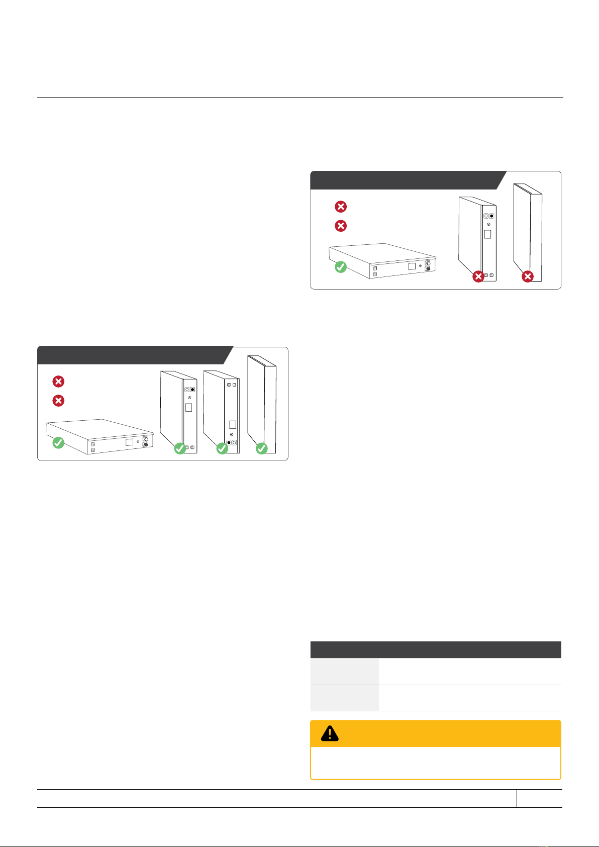
•If the battery is installed into enclosures without rails,
please ensure that they are securely seated to prevent
accidental damage or tampering.
•If a custom enclosure or mounting method is used, please
ensure the batteries are not stacked more than 6 high
unless battery support rails are used to distribute weight.
•Please ensure there is adequate air ow around the
battery stack within the cabinet. Except for the top and
bottom surfaces of the stack, a clearance of at least
25mm is required around the stack (4 sides of the stack).
WARNING
If the battery is not stored or operated within the
recommended temperature range specied in Section
5.1, the Battery Management System (BMS) may halt
the operation of the battery as a protective measure. It is
important to note that if the battery is subjected to extreme
temperatures frequently, there will be a negative impact to
its long-term performance and reduce its longevity.
5.1 LOCATION AND ENVIRONMENT
The location of the battery should be in accordance with
the IP rating in Table 4.4 (Physical Characteristics) and
operating temperature range specied in Table 4.3 (Operating
Conditions).
The LiFe4838P battery is designed to be installed in a 19-
inch data rack assembly or an electrical enclosure of your
choice. The external rack assembly or electrical enclosure
is considered outside the scope of the battery product
certication. If the battery is to be installed outdoors a suitable
enclosure with IP54 (or greater) rating should be used.
The location of the battery should meet the below conditions:
•Due to the risk of short circuits and rapid metal corrosion,
the battery should not be installed where direct contact
of salt air may be possible. If salt air is unavoidable,
appropriate air ltration must be employed to keep the
battery free of salt deposits. It is highly recommended that
the battery should be installed in an indoors environment,
or inside an IP66 or greater enclosure.
•The oor is level and free from obstructions.
•There are no explosive or ammable materials nearby.
•The recommended operating temperature is between
15°C and 30°C.
•The temperature and humidity should remain as constant
as possible.
•The area is of a clean environment with minimal dust.
•The area or enclosure is insect and vermin proof.
•The batteries and battery cabinets/housings are not
exposed to direct sunlight.
5.1.1 EXTREME HUMIDITY CLIMATES
When PowerPlus Energy’s LiFe4838P batteries are being
installed in elevated humidity conditions, extra precautions
should be taken:
•A humidity control agent (i.e., chemical which absorbs
humidity) may be required inside the enclosure, with
controlled airow to expel moist air.
NOTE
The battery will exhibit optimal performance and lifespan
if it is operated within its ideal temperature range.

PowerPlus Energy Pty Ltd • LiFe4838P Installation and Operation Manual 19/10/2023 | V2.5 page 10 of 20
•Please ensure the selected IP rating is correct as per your
location selection.
•All interconnecting battery cables for parallel connection
shall be the same length and cable size.
•A busbar is recommended for connection of all parallel
battery connections.
•An appropriate way of connecting the cabinet to the
PCE should be considered.
•Please follow PCE instructions for fuse, cable, and
connection requirements. These will vary depending
on brand and product selected.
5.2.2 BATTERY ORIENTATION FOR STATIONARY
APPLICATIONS
In stationary applications, other than resting the battery on its
front face or resting it on its lid (upside down), the battery can
be mounted in any of the other four possible orientations:
5.2.3 BATTERY TRANSPORTATION WITHIN A PRE-
ASSEMBLED BESS
If the battery is to be pre-installed into a BESS in which
it is shipped, the following guidance must be followed:
•The battery should be shipped horizontally and secured
in place to limit movement.
•If the battery is to be subjected to prolonged vibrations
during transportation, a sucient non-ammable shock
mount system (like high density foam or similar) should
be installed within the BESS under the battery.
If the guidance above cannot be followed, the battery must
be removed from the BESS and shipped in the original
manufacturer’s packaging.
5.2.4 BATTERY INSTALLATION IN MOTORHOMES,
RV’S, TRAILERS, VEHICLES, TRUCKS, BUSES OR
SIMILAR
•The battery should be installed horizontally (with the
lid upwards) and secured in place to limit movement.
•The battery should be positioned in a non-ammable
section and be vented to the outside, easily accessible,
and removable from outside of the vehicle.
Upside down on lid
On face of battery
Battery can be only mounted as shown
•A sucient non-ammable shock mount system (like
high density foam or similar) should be installed under
each battery.
•Batteries can be stacked no more than four high.
5.3 BATTERY CONNECTIONS
Each battery has a positive and negative Amphenol SurLok
(non-keyed) connector for easy snap on connection. A range
of cables and mating connectors are available from any
PowerPlus Energy place of purchase.
If multiple batteries are being used in parallel, the battery
cables shall all be of the same length to retain equal
impedance of each battery and cable set.
5.3.1 MAIN DC CONNECTIONS
The battery comes tted with Amphenol Surlok connectors
(non keyed) connectors. The table below outlines the battery
connections and the mating cable connectors required. Each
battery when ordered separately (without a cabinet) will come
supplied with mating connectors.
Each Amphenol SurLok connector supplied by PowerPlus
Energy can adequately seat 25mm single insulated or 16mm
double insulated cable. A 16mm reducing sleeve is provided.
Crimping of SurLok to the stripped end of the cable is
performed using a standard 25mm hex crimp tool.
Before connecting the DC cable to the battery you will need to
remove the safety insulating cap on the battery DC connectors
and dispose of appropriately.
WARNING
Do not connect the main DC cable with reversed polarity.
It will cause severe damage to the battery.
Figure 5.2
Figure 5.1
Upside down on lid
On face of battery
Battery can be only mounted as shown
Battery Cable
Positive
connection SLPRATPSR SLPPA16BSR
Negative
Connection SLPRATPSB SLPPA16BSB

PowerPlus Energy Pty Ltd • LiFe4838P Installation and Operation Manual 19/10/2023 | V2.5 page 11 of 20
5.3.2 CASE EARTHING
The LiFe4838P battery case is designed to be electrically
oating and isolated from all internal battery connections and
in most installations will not require earthing. However, should
your application require the case to be grounded a 5mm M6
bolt should be used and is supplied with the battery.
A range of cables to connect the battery alarm contacts
are available for purchase.
Description Part Number
Battery Bridge connector COMLBA
Battery daisy chain
connector lead (30cm) COM003A
Battery Comms Cable (2m) COM020A
Battery Comms Cable (5m) COM050A
Battery Comms Cable (10m) COM100A
Battery Comms Cable (15m) COM150A
1 Unused
2 Unused
3 Unused
4 Unused
5 Unused
6 Alarm
7 Unused
8 Unused
Table 5.1
5.3.3 BATTERY ALARM OUTPUT
The battery is equipped with a Battery Alarm Output that
noties an external system when the Battery Management
System (BMS) or the DC Circuit Breaker has tripped. The BMS
trip will self-reset once the fault has been resolved or removed,
however if the battery’s DC Circuit Breaker has tripped, it will
need manual intervention.
The Battery Alarm Output is presented on the two RJ45
connectors on the front panel of the battery. The Battery Alarm
Output is present on pins 5 and 6 of the RJ45 connectors as a
pair of volt-free contacts. These volt-free contacts can be used
to signal to an external PLC or alarm circuit.
The Battery Alarm Output is normally closed when energised
by the battery (battery is ON and LED illuminated). When the
BMS or DC Circuit Breaker trips, the battery turns OFF (circuit
breaker or BMS trip and LED o) and the contacts will open.
The alarm outputs are designed to be daisy chained (using
P/N COM003A comms cable), connecting the bottom RJ45
of a battery to the top RJ45 of the battery immediately below,
and so on. The battery at the end of the chain (generally the
bottom battery) will need to the have pins 5 and 6 bridged on
the bottom RJ45 terminals using a bridging connector (P/N
COMLBA). The top connector on the rst battery in the chain
(generally the top battery) can be connected to an appropriate
alarming circuit using one of our battery comms cables.
Advanced
Status LED
Main DC
Terminals
Case Earth
Connection
Figure 5.3
Figure 5.4

PowerPlus Energy Pty Ltd • LiFe4838P Installation and Operation Manual 19/10/2023 | V2.5 page 12 of 20
DIGITAL
INPUT
Max Input
60V 100mA
Ethernet
Cable
Loop back
connector
COMLBA
VICTRON
CEBRO GX
(Self Powered)
DIGITAL
CTRL IN
Max Input
60V 100mA
12V 0.8A power
supply from
comms board
Ethernet
Cable
Loop back
connector
COMLBA
SELECTRONIC
SP PRO
(External Powered) Specic examples on how
to use alarm contacts.
Figure 5.5
Figure 5.6

PowerPlus Energy Pty Ltd • LiFe4838P Installation and Operation Manual 19/10/2023 | V2.5 page 13 of 20
6.2 DC CIRCUIT BREAKER
Each battery has an integrated DC circuit breaker. Firstly, it is
the ON/OFF switch for the battery. Secondly, it protects the
battery in the event of an internal battery fault. Finally, it is also
used to safely and easily isolate the battery from the DC bus
inside the rack or the Battery Energy Storage System (BESS).
6.1 STATUS LED
The Status LED indicator is used to provide a visual indication
of the operation and state of the battery.
Status Operational State
ON Battery is ON and allowing charge and
discharge.
OFF Battery circuit breaker is in the OFF position.
OFF
Battery BMS is in low voltage protection mode:
Charge and discharge will not be permitted until
battery is recovered by a certied technician.
FLASH Battery is in the protection mode. The detailed
information is listed in Section 7.
6. BATTERY OPERATION
Now that you have installed the batteries you are almost
ready to energise the system. First you should check your
installation to ensure the below:
•Check polarity of all battery connections to be correct.
•Check that there is no damage to cables.
•Check that all system breakers are in the o position.
•Check for adequate air ow as per your installation
requirements.
If a fault occurs, the battery will enter its protection mode, and
the Status LED will start to ash several times periodically to
indicate the fault. The error codes in the Section 7 can help
diagnose and troubleshoot problems quickly and eciently.
IMPORTANT
IMPORTANT
If the power system has been shut down or charging source
has been removed, the battery should have its circuit breaker
switched to the OFF position within 7 days.
Table 6.1
•Check for local installation compliance if applicable.
Starting up the battery system should be done in conjunction
with the PCE manufacturer’s recommendations as well
as this manual and any local or government safety
requirements.
Each battery in the system is powered up separately by
turning the double pole breaker to the ON position. Once
powered up, voltage will be present at the DC terminals and
the Main Status LED light will glow blue.
DC
Circuit
Breaker
Advanced
Status LED
Main DC
Terminals
Alarm Port
Case Earth
Connection

PowerPlus Energy Pty Ltd • LiFe4838P Installation and Operation Manual 19/10/2023 | V2.5 page 14 of 20
6.2.1 BATTERY SYSTEM STARTUP
The battery system should be started following the startup
procedure supplied with the system.
The LiFe4838P battery does not provide an output voltage
until it is turned on. In most cases powering on the battery
will be one of the rst steps of starting your power system.
1. Locate and ensure your main system isolation point
is OFF.
2. Check all battery connections are tight and secured.
3. Systematically turn each battery DC circuit breaker
to the ON position (switch to the right when looking
at the front face of the battery).
4. Status LED will illuminate indicating voltage is present
at the battery terminals.
5. Turn on main system isolation.
6. Turn on PCE.
6.2.2 BATTERY SYSTEM SHUTDOWN
Use the following steps to shut down the battery system:
1. Turn o the PCE.
2. Turn o main system isolation.
3. Turn o each battery by turning its DC circuit breaker
to the OFF position.
4. Ensure the Status LED on all batteries in the rack
are no longer illuminated.
6.3 CHARGING AND DISCHARGING
As outlined in the Table 4.3 (Operating Conditions), whilst
being charged, the battery temperature should be between
4° and 51°C. Whilst being discharged the battery temperature
should be between -6° and 56°C. When there are multiple
battery charging devices and multiple batteries in a system,
please ensure that the maximum current owing into and out
of each battery is kept below 63A per battery (in accordance
with the Maximum Continuous Charge Current and Maximum
Continuous Discharge Current given in Table 4.2).
6.3.1 FULL RECHARGE UPON FIRST INSTALLATION
Batteries are delivered and shipped in a partial state of charge.
Prior to discharging the batteries, the entire rack should be
fully charged to the oat stage.
IMPORTANT
IMPORTANT
This initial full charge to 100% will allow the battery’s Battery
Management System (BMS) to perform Battery String
Balancing to ensure all cells are at the same state before
regular cycling. See Section 6.3.2 (Battery String Balancing)
for further details.
If the battery system (external to the battery) also has an
integrated SoC (State of Charge) counter, the initial full
charge may be needed to calibrate the counter to a known
battery SoC (some SoC counters may take a few cycles to
learn the SoC).
6.3.2 BATTERY STRING BALANCING
It is essential that the battery is allowed to perform string
balancing at least once every 7 days to improve the overall
performance of the battery and to optimise the battery’s
longevity. String balancing allows the BMS to equalise the
battery cells to limit apparent battery capacity slip and
the process ensures the battery will charge correctly on
subsequent charge cycles.
Battery string balancing is achieved by:
1. Charge the battery using a 56.4V charge source,
limited to no more than 39A.
2. Maintain the 56.4V charge voltage until the battery
is absorbing less than 0.741A.
3. Maintain the 56.4V charge voltage for a further
60 minutes.
CIRCUIT BREAKER ON
Flip the switch on circuit breaker to the right
63A DC Circuit
Breaker
LiFe4833P
LED Indicator Light
Will illuminate when
circuit breaker is on
LiFe4833P
CIRCUIT BREAKER OFF
Flip the switch on circuit breaker to the left
Figure 6.1
Figure 6.2

PowerPlus Energy Pty Ltd • LiFe4838P Installation and Operation Manual 19/10/2023 | V2.5 page 15 of 20
6.3.3 OVER-DISCHARGED BATTERY
If the battery’s low voltage protection circuit has operated to
protect the battery from excessive discharge, it is important
that the battery is charged to 100% within 7 days. Leaving the
battery in a discharged state can cause irreversible damage to
the battery and reduce long term battery capacity.
6.3.4 PRIMARY CHARGING SOURCE
A Primary Charging Source (PCS) should be identied in the
system and programmed to charge the batteries as outlined in
Table 6.4 (Connected PCE Programming Requirements). A PCS
is the charging device used to charge the battery with up to
95% of the total charge energy of the battery.
6.3.5 SECONDARY CHARGING SOURCE
A Secondary Charging Source (SCS) can also be used. The
preference is to also have these devices programmed to the
charging settings in Table 6.4 (Connected PCE Programming
Requirements). However, if this is not possible, a SCS can still
be used if all the following conditions are met:
•The SCS’s output voltage does not exceed 56.1V.
•The batteries are not charged above 63A per battery.
•The SCS provides no more than 25% of the total
charge energy of the battery.
6.3.6 PCS WITH SCS EXAMPLE
Primary Charging Source = Solar PV; will be used to supply
75% of the charging energy and will be programmed as per
Table 6.4 (Connected PCE Programming Requirements).
Secondary Charging Source = Solar Charge Controllers; will
be used to supply approximately 25% of the charging energy,
however, cannot have the voltage adjusted as per the specic
charging voltages as specied in Table 6.4 (Connected PCE
Programming Requirements), and will not exceed 56.2V nor
will it exceed the total system charge current.
6.3.7 POWER CONVERSION EQUIPMENT (PCE)
SETTINGS
Where PowerPlus Energy has released custom settings for
specic Power Conversion Equipment (PCE), such settings
take precedence over the settings provided in this document.
In the absence of custom settings, Table 6.4 provides generic
settings suitable for most PCE when using LiFe4838P.
6.4. CALIBRATION TO 100%
Internal cell balancing of the battery happens during the end of
the charging process. It is important for battery health to ensure
battery capacity does not slip over time and batteries are
charged to 100% at least once every 7 days as a minimum.
6.5. SOC (STATE OF CHARGE) DRIFT
SoC drift happens when the product that is calculating SoC
builds up an accumulative error. This error is generally due to
tolerance of components that measure voltage and current
and algorithms used to calculate how full the battery is. Most
products will reset its accumulative error when the system gets
to 100% SoC or oat.
It is important a well designed battery storage system reaches
oat or 100% as regularly as possible, preferably every 1 to 2
days to reset SoC drift, however, can be extended if required.
SoC drift can be tackled in many ways. See examples below.
1. Sucient solar sized to charge batteries to oat or 100%
on the winter Solstice
2. Backup source installed (grid or generator) to allow
charging of batteries during extended bad weather or
high load events.
3. Ascertain from PCE manufacture the accuracy of the
SoC calculator. If a higher more accurate shunt can be
used with the PCE to monitor system SoC, then this
should considered.
LiFe4838P Connected PCE Programming Requirements
Shutdown DC Voltage @0.5C 48V
Shutdown Voltage Recommended 50.2V
Recovery / Restart Voltage 52V
Continuous Charge Voltage 56.4V
Continuous Charge Transition
Battery is considered full after battery
is absorbing less than 0.741A after
being held at specied charge
voltage for 30 minutes minimum.
Float Voltage Cyclic
(Short Term Float)
(Example Solar Application)
56.4V
Float Voltage Standby
(Long Term Float)
(Example UPS Application)
54.4V to 56.4V
Charge Current 39A
Peukert Exponent 1.02
Shutdown SoC Recommended 20%
Calibration to 100%
Every 7 days or more frequent
where possible. (Ensures cell
balancing is performed, keeping
external SoC counter more
accurate, see Section 6.3.2)
These charging requirements are subject to change at any time without notice
Table 6.4

PowerPlus Energy Pty Ltd • LiFe4838P Installation and Operation Manual 19/10/2023 | V2.5 page 16 of 20
7. TROUBLESHOOTING
This section is designed to help you identify and resolve
common issues you may encounter while using our battery.
For each issue, we have provided possible causes and
suggested solutions. If you cannot resolve the issue or
need further assistance, please do not hesitate to contact
our Customer Support team at the number provided below.
Customer Support Line: +61 (3) 8797 5557
support@powerplus-energy.com.au
Available Monday to Friday, 9 AM to 5 PM [AEDT]
During normal operation of the LiFe4838P battery, whilst
the DC Circuit Breaker is in the ON position, there will be
No. of Flashes LED Status Action
2 Flashes One or more cell-strings under-voltage Use constant current charger to re-charge battery.
See manual soft start procedure.
3 Flashes One or more cell-strings over-voltage Apply load to discharge battery.
4 Flashes Over-current whilst charging Discharge battery with load over 55W per battery.
5 Flashes Over-current whilst discharging Remove load.
6 Flashes Short-circuit across battery terminals OR
High-level over-current whilst discharging
Remove short circuit. Assess load and capacity of battery
to drive load, add additional battery modules.
7 Flashes Cell-pack over-temperature whilst charging Turn o charging devices until battery cools and resets.
8 Flashes Cell-pack over-temperature whilst discharging Turn o discharging devices until battery
cools and resets.
9 Flashes Cell-pack under-temperature whilst charging Wait until the battery warms up. Alternatively warm the
battery with an external heating device.
10 Flashes Cell-pack under-temperature whilst discharging Wait until the battery warms up. Alternatively warm the
battery with an external heating device.
11 Flashes BMS over-temperature Remove load and allow battery to cool.
12 Flashes BMS under-temperature Warm the battery with external heating devices.
13 Flashes Cell-pack under-voltage Use constant current charger to re-charge battery.
See manual soft start procedure.
14 Flashes Cell-pack over-voltage Apply a load to discharge battery.
15 or 16 Flashes Cell-pack critically under-voltage Contact PowerPlus Energy.
Table 7.1
a voltage present across the terminals of the battery.
However, when the operation of the battery goes outside its
design limits, the Battery Management System (BMS) will enter
an alarm state. During this alarm state, there will no longer be a
voltage present across the terminals of the battery, If the BMS
activates its alarm state, once the fault is cleared, the battery
may need external assistance to restart depending on the type
of fault. To recover from a fault condition, the user/installer will
need to take the relevant remediation action listed in Table 7.1.

PowerPlus Energy Pty Ltd • LiFe4838P Installation and Operation Manual 19/10/2023 | V2.5 page 17 of 20
NOTE
Your installer or PowerPlus Energy should be consulted
if your battery will not activate.
7.1 OVER-DISCHARGED BATTERY RECOVERY
7.1.1 SOFT SHUTDOWN (2 FLASHES)
Use an approved battery charger. Contact PowerPlus Energy.
7.1.2 BMS THRESHOLD SOFT SHUTDOWN
Soft shutdown occurs if the voltage in the battery reaches a
designated LOW level. In the soft shutdown state, the battery
will not provide a DC voltage at its terminal (voltage will be <4V)
until the system has been reset.
The time you have to recover the battery when it has
performed a soft shutdown will vary depending on model. The
battery will not deliver power to a load from its DC terminals
until the battery module reaches a designated recovery
voltage.
7.1.3 SOFT SHUTDOWN RECOVERY
This procedure is a guide and should be performed by suitably
qualied person.
1. Shutdown system following your shutdown procedure.
2. Ensure all loads are switched o.
3. Turn o battery/s via DC circuit breaker and wait 30
seconds.
4. Turn on battery via DC circuit breaker.
5. Wait for battery Main Status LED to illuminate.
6. Connect and turn on site PCE.
7. If the PCE starts up, action a full charge cycle to occur.
8. If battery will not turn on or remain on long enough start
a PCE charge. Please follow Hard Shutdown Recovery.
7.1.4 HARD SHUTDOWN (15 OR 16 FLASHES)
If a battery has been left unused for a long period without
charge, it may become excessively self-discharged and enter
a Hard Shutdown mode.
Also, if a battery has become damaged for some unexpected
reason, it may also enter a Hard Shutdown mode to protect
itself and the users.
Once Hard Shutdown occurs the battery can no longer be
charged or discharged.
7.1.5 HARD SHUTDOWN RECOVERY
Hard Shutdown is not a user-serviceable fault.
Contact your installer or PowerPlus Energy.

PowerPlus Energy Pty Ltd • LiFe4838P Installation and Operation Manual 19/10/2023 | V2.5 page 18 of 20
8. MAINTENANCE
The LiFe4838P is designed to require no regular
maintenance from users. However, as part of your overall
system maintenance, some checks can be carried out at
least yearly.
•Check Status LED.
•Check battery DC Circuit Breaker by turning it o
and on again.
•Check battery connections and cables for secure
tting or damage.
•Check for any obstruction placed around the battery
or battery enclosure.
•Check for animals, insects or creatures nesting in
or around the battery enclosure.
•Check for build-up of any foreign objects in or
around the cabinet.
9. UPGRADING BATTERY CAPACITY
It is possible to add additional batteries to an existing
LiFe4838P installation at a later date. It is not possible to
mix and match dierent battery types and capacities to
an existing battery rack. Therefore, all batteries in a rack
must be of the same type, part number, and specication
– unless advised to the contrary by PowerPlus Energy.
Before adding one or more new batteries to the rack, this
new battery voltage and the existing battery rack voltage
must be within 0.2VDC of each other.
This may be achieved by using one of the following
methods:
•By charging both the new battery and the existing
battery to fully charged separately before combining
them into the same battery system.
•Insert the new battery to a partially discharged
battery bank ensuring the new battery and
the battery bank are within 0.2V of each other.
Charge banks up and maintain our recommended
continuous charge voltage for 6 hours before oating
or allowing load to be applied.
•If the battery rack is lower in voltage, charge it up
slowly to be within 0.2VDC of the new battery or
batteries. Conversely, if the rack is higher in voltage,
discharge the rack slowly until it is within 0.2VDC
of the new battery or batteries.
Remember to update all PCE charging current and
battery capacities to reect the new increased battery
storage system capacity.

PowerPlus Energy Pty Ltd • LiFe4838P Installation and Operation Manual 19/10/2023 | V2.5 page 19 of 20
11. COMPATIBLE GRID-CONNECT
HYBRID INVERTERS
10. CAPACITY TESTING THE BATTERY
Visit the PowerPlus Energy website to access the latest
list of compatible inverters or click the link below to
access the document directly.
https://www.powerplus-energy.com.au/les/LiFe4838P_
Inverter_Declaration.pdf
The battery capacity can be measured and veried
by following the below test procedure. This should be
performed using calibrated test equipment and performed
by a suitably qualied person. To determine the battery
capacity, the below process should be conducted by
a suitably qualied professional and performed at an
ambient temperature of 25°C:
•Discharge the battery at 0.5C until the low voltage
cut-o is reached, this will be determined by the
BMS going open circuit.
•Charge the battery at the recommended continuous
charge voltage and 0.5C rate and hold at that
voltage for 6 hours.
•Discharge the battery with a constant load at 0.5C
until the low voltage cut-o is reached. This will be
determined by the BMS going open circuit.
•Record the number of hours it takes to reach low
voltage cut-o point.
•Charge the battery at the recommended continuous
charge voltage and 0.5C rate for 6 hours.
The State of Health of the rated capacity can now be
calculated as below and as a % of original capacity:
((((Ah×0.5)×Discharge hrs))⁄Ah)×100
Ah = Amp Hour Capacity
0.5 = 0.5C constant load discharge
100 = Conversion to %
Example:
LiFe4838P Ah Capacity = 74.2Ah
Battery time to discharge under test = 1.85hrs
= (((74.2*0.5)*1.85)/74.2)*100
= 92.5%

PowerPlus Energy Pty Ltd • LiFe4838P Installation and Operation Manual 19/10/2023 | V2.5 page 20 of 20
13. WARRANTY12. END OF LIFE
PowerPlus Energy will protect this product under warranty
when it is installed as written in this manual and used
as set out in the warranty documents. Any product not
being used or installed as outlined will be in violation of
the terms and will render the product void of any warranty.
PowerPlus Energy does not cover warranty or any liability
for damages or defects caused or from the following:
•Incorrect storage or transportation.
•Incorrect installation and wiring.
•Installed not according to this manual.
•Incorrect operation.
•Inappropriate environmental conditions when
operating the battery.
•Failure to follow safety requirements.
•Tampering of or opening the battery.
•Unauthorised repairs or modications.
•External inuences such as physical damage, over
charging or electrical damage.
•Used outside of warranty terms and conditions.
When a PowerPlus Energy battery is removed from
service it can be returned to PowerPlus Energy for
recycling.
Due to the stability and longevity of LFP cylindrical cells,
returned batteries will be refurbished and checked so they
can be repurposed for low power applications and made
available for community, education, and charity projects.
Any Lithium cells not suitable for repurposing will be
sent to a licensed recycling facility, where all ferrous and
nonferrous metals are separated and then forwarded to
our metals recycling partner.
Other manuals for LiFe4838P
1
Table of contents
Popular Batteries Pack manuals by other brands

XTline
XTline XT102784E Original instruction manual

DLG Energy
DLG Energy SOLUNA installation manual

C&D Technologies
C&D Technologies UPS12-100MR Maintenanse Instructions

Viking
Viking VIDAR I user manual

Enerwatt
Enerwatt EWGR-31-500W user manual

Power Innovations
Power Innovations Q-LS Installation and operation manual