Powtran PI7800 User manual

Foreword
Thankyou verymuchforpurchasing PI7800 PI7600 FamilyFrequency
Inverters.Thisfamilyisdesigned based on theexperienceof
POWTRANCompanyinthe professionalmanufactureand saleofthe
products,and suitableforgeneral-purposemachine,fan/pumpdrive,
high frequency driveand heavyload machine.
ThisUser sManualprovidestheuserswiththe instructionson the
installation,parametersetting,faultdiagnosis,routine maintenanceand
necessary precautions.Pleaseread the Manualcarefullybeforethe
installationofthe productinordertoensurethatitcan be correctly
installedand operated.
ThisUser sManualincludesPI7800 PI7600,the generalpurpose
controland specialpurposecontrol.The generalpurposecontrolha
F,G ,Mand H;The specialpurposecontrolhasS,T andZ:
F: FLOWLOAD
G:GENERALLOAD
M: MEIDDLELOAD
H: HEAVYLOAD.
S: TEXDRIVE.
T: WINDLASS.
Z: JETDRIVE.
Pleasecontactthe localdealersordirectlycontact ourcompany.
Pleasekeep thisuser smanualingood condition, foritwillbe helpfulto
the repair, maintenance, and applicationsinthe future.
Forinformation about otherproduct,pleasevisit ourwebsite:
http://www.powtran.com.
CONTENTS
Section I. Inspection and SafetyPrecautions.........................1
Section II. Installation & StandbyCircuit................................3
Section III. Operating keyboard..........................................14
Section IV. Test running....................................................19
Section V. Function parametertable...................................21
Section VI. Function ParameterDescription ..........................34
Section VII. Fault DiagnosisandSolutions.............................88
Section VIII. StandardSpecifications.....................................90
Section IX. Maintenance.................................................103
Section X. Options........................................................105
Appendix1. PI7000 RS485 communication protocol...............109
Appendix2. PGInstruction...............................................120
Appendix3. Converterwatersupplycontrollerinstruction ........123
PDF 件使用 "pdfFactory Pro" 试用版本创建 ÿwww.fineprint.com.cn

1
SectionI.InspectionandSafetyPrecautions
POWTRANPI7800/7600 frequency invertershavebeentestedand inspected
beforeleavingthemanufacturer.Beforeunpackingtheproduct,pleasecheck if
itspackageisdamagedduetocareless transportation,andifthespecifications
and typeoftheproductcomplieswiththeorder.Pleasecontactthesupplierof
POWTRANproductsif anyproblemsarefound.
1-1.Inspection after Unpacking
※Inspectthatthecontentsarecomplete(onePI7000/7100frequency
inverter, oneOperationManual).
※Check thenameplateon thesideofthefrequency invertertoensurethat
theproductyouhavereceivedisrighttheoneyouordered.
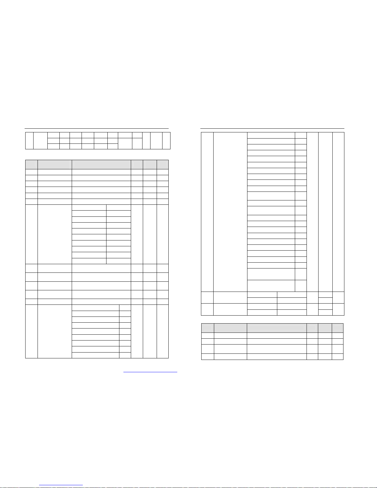
Instructionsonnameplate: (giving132kW/380Vasexample)
PI7800132G3
POWTRANTECHNOLOGY CO.,LTD.
3380V50-60Hz
132KW250A0.00-800.0Hz
Z0501A00001
TYPE:
OUTPUT:
SOURCE:
Model designation:
1-2.SafetyPrecautions
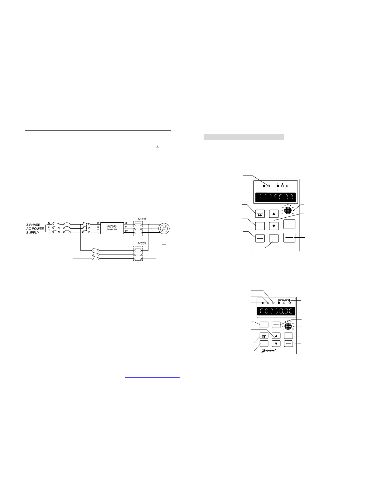
※NeverconnecttheA.C.powersupplytotheoutputterminals(U,V,W)of
SECTION I. INSPECTIONAND SAFETY PRECAUTIONS
2
thefrequency inverter.
※Fixandlock thepanelbeforesupplyingpowersoastoavoidthedanger
causedbythepoorcapacityorothercomponentsinsidetheinverter.
※Afterthepowersupplyisswitchedon,donotperformwiringorcheck, etc.
※Donttouchthecircuitboardsoritspartsorcomponentsintheinverter
whenitispowered, soastoavoiddangerofelectricshock.
※Ifthepowersupplyisswitchedoff,do nottouchthePCBorotherparts
insidetheinverterwithin5minutesafterthekeyboardindicatorlampgoes
off,and youmustcheck byusingtheinstrumentthattheinverterhas
completelydischargedallitscapacitybeforeyoustarttoworkinsidethe
inverter.Otherwise,therewillbethedangerofelectricshock.
※Thestaticelectricityinhumanbodywillcauseseriousdamage totheMOS
fieldeffecttransistorintheinverter.Pleasekeepyourhandsawayfromthe
PCB,IGBTandotherinternalpartsbeforetakingactionstopreventstatic
electricity. Otherwise,faultsmaybecaused.
※Inuse,theearthing terminal(Eor )ofthefrequency invertermustbe
groundedtotheearthingconnectionscorrectlyandsecurelyaccordingto
thenationalelectricalsafetyspecificationsand otherapplicablestandards.
※Pleasedontshutoff theunitbyturningoffthepowersupply.Turnoff the
powersupplyafterthemotorhasstoppeditsoperation.
※Meet CEstandardwithEMIfilter.
1-3.Application
※Powtraninverterisgenerallyappliedto3phaseACasynchronismmotors.
※Powtraninverterisappliedtotheadmisiveoccasion,theoccasionwhereis
notadmissivemaylead tofire, electricshock, explosion and soon.
※If theinverterseizesup whenit isappliedtotheequipmentwhichmaylead
danger(e.g.lifttoolsoftransportation,aviationsystem,saftetyequipment,
etc),itshouldbemanagedcarefully.Doinquirethefactorywhenit
happens.
Onlythewell-trainedpersonnelare allowedtouse this
unit,and suchpersonnelmustreadthroughthepartsofthis
manualrelatingtothesafety,installation, operation and
maintenance before usingtheunit.Thesafeoperationofthis
unitdependsoncorrecttransport,installation,operation and
maintenance!
PDF 件使用 "pdfFactory Pro" 试用版本创建 www.fineprint.com.cn

3
SectionII.Installation&StandbyCircuit
2-1.ConditionsforUse
1)Ambienttemperature-10 ~40 .
2)Avoidelectromagneticinterferenceand keeptheunitawayfromthe
interferencesource.
3)Preventdroppingwater,steam,dust, powder,cottonfiberorfinemetal
powderfromentering it.
4)Prevent oil,salt and corrosivegasfromenteringit.
5)Avoidvibration.
6)Avoidhigh temperatureand moistureand avoidbeing wettedduetoraining,
withthehumiditybelow90%RH (not dewing).
7)Prohibittheuseinthedangerousenvironmentwhereinflammableor
combustibleorexplosivegas,liquidorsolidexists.
2-2.Installation
Thefrequency invertermust beinstalledbywallhooking inthe indoorroomwith
adequateventilation,withenoughspaceleft betweenitand theadjacent
objectsordamper(walls)surroundingit, asshowninthebelowfigure:
150MM 150MM
+ -
STOP
RESET
REV
JOG
DISPL
ESC
SET
FWD
PRG 50MM50MM
2-3.Wiring
Thewiringoffrequency inverterincludestwoparts:maincircuitandcontrol
circuit.Theusermustensurecorrectconnectionsaccording tothefollowing
connectiondiagram.
SECTION II. INSTALLATION &STANDBY CIRCUIT
4
2-3-1.PI7800 Diagram
1.Wiringdiagram7.5KW~15KWandbelow
PDF 件使用 "pdfFactory Pro" 试用版本创建 www.fineprint.com.cn

SECTION II. INSTALLATION &STANDBY CIRCUIT
5
2.Wiringdiagram18.5KW~22KW
SECTION II. INSTALLATION &STANDBY CIRCUIT
6
3.Wiringdiagram30~160KW
PDF 件使用 "pdfFactory Pro" 试用版本创建 www.fineprint.com.cn

SECTION II. INSTALLATION &STANDBY CIRCUIT
7
4.Wiringdiagram1187~355KW
SECTION II. INSTALLATION &STANDBY CIRCUIT
8
2-3-2.PI7600 Wiringdiagram
1.Wiringdiagram7.5KWandbelow
PDF 件使用 "pdfFactory Pro" 试用版本创建 www.fineprint.com.cn

SECTION II. INSTALLATION &STANDBY CIRCUIT
9
2-4.MainCircuitTerminals:
2-4-1. PI7800 MainCircuitTerminals
1. 7.5KW~15KW(380V)MainCircuitTerminal
2. 18.5~22KW(380V)MainCircuitTerminal
3. 30~160kW(380V)MainCircuitTerminal
Note: P/P+Standardsettingisshortcircuit; ifit iswithexternalreactance,please
disconnect and thenconnectit.
4.187KW~355KWandabove(380V)MainCircuitTerminal (132~160KWoptional)
SECTION II. INSTALLATION &STANDBY CIRCUIT
10
2-4-2. PI7600 MainCircuitTerminal
1. 7.5KWand below(380V)MainCircuitTermial
For4N2Band4N3Bpanel, “E”ison thesteelpanel.
Note:Theabove KWcategaries areforGtypeinverter.
2-4-3.TerminalFunction
Terminal Description Functions
R/L1
S/L2
T/L3
Powerinputfor
frequency inverter Connectedto3-phasepower
(Singleinput connectedtoR,T)
E/PE Grounding point Groundedtotheearth
RB, RB′Connectionpointfor
brakingresistance Connect brakeresistance
U/T1
V/T2
W/T3 3PhaseOutput Connectedto3-phasemotor
P+, N DC Busoutput Connectthebrakeunit
P, P+ DC reactance Connect DC reactance
2-5.Control CircuitTerminals
Class
Terminal
Description Function
COM Common point forcontrol
commands
F05=1, Edgetriggers(F62=0),and runsforwardinfalling
edge, stopsinrising edge
FWD Forwardrotationcommand F05=3, Leveltriggers(F62=0/1/2)
F05=1, Edgetriggers(F62=0), andrunsreverseinfalling
edge, stopsinrising edge.
REV Reverserotation command F05=3, Leveltriggers(F62=0/1/2)
JOG Jog command Leveltriggers, and executesJOG command inalower
level, stopsinahigh level
Multi-step speed/acceleration F63=1/2,Short-circuited toCOMtocompose7-stepspeed
and acceleration, leveltriggers, effectiveinalowerlevel
Rising/Falling control F04=4,forrising control
Control signal
SS1
Frequency mode switch Switchthe frequency settingmodewithSS2
PDF 件使用 "pdfFactory Pro" 试用版本创建 www.fineprint.com.cn

SECTION II. INSTALLATION &STANDBY CIRCUIT
11
Multi-step speed/acceleration F63=1/2,Short-circuited toCOMtocompose7-stepspeed
and acceleration, leveltriggers, effectiveinalowerlevel
Rising/Falling control F04=4,forfalling control
SS2
Frequency mode switch Switchthe frequency settingmodewithSS1
Multi-step speed/acceleration Short-circuited toCOMtocompose7-stepspeedand
acceleration, leveltriggers, effectiveinalowerlevel
JOG control F63=3COMis short-circuited toSS3toexecuteJOG
reversecommand, toJOG toexecuteJOG forward
command, andthe previousJOG direction is invalid.
Three-line running control F63=1/2,F62=2Three-line terminalrunning fordetails
SS3
Program running restart Forselecting theprogram runningrestartmode
FRE Free Run Leveltriggers, and executesfree stop command inalower
level
RST Restore Leveltriggers, executesrestorecommand infalling edge.
TA1
TB1
TC1 Output signal5 TA1-TC1is open and
TB1-TC1is closed (programmable)
TA2
TB2
TC2 Output signal6 TA2-TC2is open and
TB2-TC2is closed (programmable)
SPA/COM
Output signal1
SPB/COM
Output signal2
SPC/COM
Output signal3
Output signal
SPD/COM
Output signal4
Output open collectorsignal(24VDC-50mA)
V1,V3 PowerSupply +10V, GND
V2 Voltage Input signal Rangeis adjustablein0~10V
I2 CurrentInput signal Rangeis adjustablein0~20mA
VF Voltage feedback input signal 0~10V/1~5V
IF Currentfeedback input signal 0~20mA/4~20mA
ACM Common terminalof DA1and
DA2 Used forcommon terminalwhen DA1/DA2selectsvoltage
output
V1 PowerSupply of DA1and
DA2 Used forPowerSupply whenDA1/DA2selectscurrent
output
DA1 Multi-functionanalogsignal
output1 0~10/1~5VDC
0~20/4~20mA
DA2 Multi-functionanalogsignal
output2 0~10/1~5VDC
0~20/4~20mA
Analog Input and output signal
DFM DFMmultipleadjustment Factorysetting 1:1, duty=50%, 10VDC
24V PowerPositiveterminal
Auxiliary
Power
COM Common point Maximaloutput 24V/200mA
Communication
Signal
SG+,
SG-,
SH
Communication positive/
negativesignal, Screensignal RS485 communication(refertoAppendix 1)
SECTION II. INSTALLATION &STANDBY CIRCUIT
12
2-5-2Control circuitterminal
17KLCB.V4Control circuitterminal
27KSCB.V1Control circuitterminal
2-6.ConnectionPrecautions
※Dontinstallpowerfactorcapacitanceorresistance-capacitanceabsorbing
devicebetweentheoutputterminalsU,V,Wofthefrequency inverter.
※Todisassembleorreplacethemotor,theinputpowersupplymustbe
turnedoff forthefrequency inverter.
※Themotororpowersupplycanbeswitchedon/offonlyaftertheinverter
stopsitsoutput.
※Inordertominimizetheeffectofelectromagneticinterference,asurge
absorbing deviceshouldbeinstalledifusedelectromagneticcontactorand
relay,etc. isneartothefrequency inverter.
※Forexternalcontroloffrequency inverter,aisolationdeviceshouldbeused
forthecontrollinesorscreenedcableshouldbeused.
※Ascreenedcableshouldbeusedasthesignalconnectionlineforinput
commandandmustberoutedseparatelyaswell,and ithad betterbe
installedfarfromthemaincircuit.
※Whenthecarrierfrequency isless than 3kHz,thedistancebetweenthe
frequency inverterandmotormustnotbegreaterthan50meters
(maximum). Whenitisabove4kHz,thisdistanceshouldbereduced.The
cableforthisconnection had betterbelaidinmetalconduit.
※Ifthefrequency inverterisequippedwithperipheraldevices(suchasfilter,
reactor),firstmeasureitsinsulationresistancetotheearthwith1000V
megohmmeter, andensuretheresistancevalueisnotbelow4MΩ.
※If thefrequency invertermustbestartedfrequently,dontswitchoffits
powersupply, and theoperatormuststartorstop theinverterbyusing the
COM/FWDof thecontrolterminalorKeyboardorRS485, inordertoavoid
damagetothebridgerectifier.
PDF 件使用 "pdfFactory Pro" 试用版本创建 www.fineprint.com.cn

SECTION II. INSTALLATION &STANDBY CIRCUIT
13
※DontconnectA.C.inputpowertotheoutputterminalsU,V,Wofthe
frequency inverter.
※Inordertopreventunexpectedaccidents,earthing terminalEor must
begroundedtotheearthsecurely(thegrounding resistanceshouldbe
below100Ω).Thecablesizeshouldbegreaterthanhalfofbelow-
mentionedcorresponding cablesize;otherwisecurrentleakagewillhappen
possibly.
※Forwiringofmaincircuit,pleaserefertonationalrule.
※Capacityofthemotorshouldbeequaltoorsmallerthanthatoftheinverter.
2-7.Standbycircuit
When thefaultortripoftheinvertermaycausegreatlossoraccident,please
add thestandbycircuit.
Note: confirmand testtherunning characteristicofthestandbycircuit,inorder
toensuretheindustrialphaseand theconverterphaseareinthesamedirection.
I
nterlock relay
14
SectionIII.Operatingkeyboard
3-1.Operatingkeyboard
☆JP3E7000 keyboard
Specificationandfunctiondescription
ALARM
RUN VAHZ
PRG
ESC
DISPL
SET
JOG STOP
RESET
RUN
JP-01
DIGITALOPERATOR
% S
℃
Paramiter
setting/shiftkey ParameterAlternation
Key(acc/reductionkey)
Acc. selection/
Parametersetting
Escape/Display
RunIndicationLight
Runkey
Stop/Resetkey
AlarmIndicationLight DataunitPrompt Light
Jogkey
Potentiometer
LEDmaindisplayarea
Thedetailedfunctiondescription isinthefollowing text (JP5E7000).
*JP3E7000KeyboardisoptionalforPI7800,PI76000Familyinverter.
☆JP5E7000 Keyboard
Specificationandfunctiondescription
% S
℃
SET
ESC
DISPL
JOG
JP-08
DIGITALOPERATOR
RUN
STOP
RESET
PRG
REV
Forwardcommand light
Reversecommand light
Paramiter
setting/shift key
Acc. selection/
Parametersetting
Escape/Display
Runkey Stop/Reset key
AlarmIndicationLight
DataunitPrompt Light
Jogkey
Potentiometer
LEDmaindisplayarea
ParameterAlternation
Key(acc/reductionkey)
ALARMFWD VA
H
Z
PDF 件使用 "pdfFactory Pro" 试用版本创建 www.fineprint.com.cn

SECTION III. OPERATINGKEYBOARD
15
Function description
Run key:
²driveforward.
Stop/Reset key:
²Drivestops,resetsafterabnormityand confirmsfault.
Acc.Selection/Parametersetting:
²When selectparameter,presstheSETkeyandadd/reductionkey,
parametercodeadd/reduce10
²Restoremodifiedvalue
²alternatethemonitorobject and monitor
Escape/display
²Escapemodifyingthedataoffunctionparameters
²Escapeofsubmenu orrunningintomenuofstatusdisplayfromfunction
menu
²Escapeoffaultstatus.
Jog key
²On:jog
²Off:stop
LEDmaindisplayarea
²Anterior3digitsdisplaythefunctioncode
²Latter4digitsdisplaythevalueasperthefunction code
DataunitpromptLight:
²Itisformed upby3instructionlightontherightupsideofthekeyboard,
different statusindicatesdifferent unitofthecurrent parameterdisplayedin
theLED.Theunitsfortheparametersasblow:
OFFON
°C
S
%VA
Hz
S
V
%
A°C
Hz
UNIT
UNIT
Hz
°C
A
%
V
S
S
V
%
A°C
Hz
UNIT UNIT
Hz
°C
A
%
V
S
S
V
%
A°C
Hz
UNIT
UNIT
Hz
°C
A
%
V
S
none
S
V
%
A°C
Hz
UNIT
*JP5E7000isthestandardkeyboardforPI7800,PI7600 Familyinverter.
uForthe4keypads,whenthekeypad isunlocked,press the and
simultaneouslyfor3seconds,thekeypad islocked,LEDdisplaysnormally
afterdisplaying “LoC”for2seconds;whenthekeypad islocked,press the
and simultaneouslyfor3seconds,thekeypad isunlocked,LED
displaysnormallyafterdisplaying “ULoC”for2seconds.
SECTION III. OPERATINGKEYBOARD
16
☆JP6E7000,JP6C7000 keyboard
Specificationandfunctiondescription
Forwardcommand light
Reversecommand light
Paramiter
setting/shiftkey
Acc. selection/
Parametersetting
Escape/Display Stop/Reset key
AlarmIndication Light
Jog key
LED maindisplayarea
ParameterAlternation
Key(acc/reduction key)
LED maindisplayarea
Positive/Negative
Valueindication light
SpeedStatuslight
*Displayofrunningstatus
Off:Stopstatus
Flash:Acc/decstatus
On:Even Speedstatus
FWS/REV Indication light
Forwardkey
Reversekey
+-
ALARM
SPEED-STATUS REV
SET
PRG
DIGITAL OPERATOR
FWD
ESC
DISPL
JOG
REV
FWD
STOP
RESET
JP-07
functiondescription
Forwardkey:
²Driveforward.
Reversekey:
²Drivereverse.
Stop/Reset key:
²Drivestops,resetsafterabnormityand confirmsfault.
Acc.Selection/Parametersetting:
²When selectparameter,presstheSETkeyandadd/reductionkey,
parametercodeadd/reduce10
²Restoremodifiedvalue
²alternatethemonitorobject and monitor
Escape/display
²Escapemodifyingthedataoffunctionparameters
²Escapeofsubmenu orrunningintomenuofstatusdisplayfromfunction
menu
²Escapeoffaultstatus.
Jog key
²On:jog
²Off:stop
TheupperLEDmaindisplayarea
²Displayfrequency,current, voltage,etc.Alsodisplayfuultcode,password
PDF 件使用 "pdfFactory Pro" 试用版本创建 www.fineprint.com.cn

SECTION III. OPERATINGKEYBOARD
17
right
FWD/REVIndicationlight
²Displaymotor srunningstate:forwardorreverse.
ThenetherLEDmaindisplayarea
²Displayfunctioncode
²Displaysetfrequency during running
JP6E7000isstandardkeyboardforPI7800,PI7600Familyinverter.
JP6C7000keyboardhasthesamestructureandinstructionwiththoseof
JP6E7000.ThedifferenceisthatthelowerLEDdisplayischangedintoLCD
displaywhichdisplaysthestateandparametersinEnglish.JP6C7000isthe
optionalkeyboardforPI7800,PI7600.
Thesecond
monitorselect
F65=4outputvoltage
The third
monitorselect
F66=2motoractualcurrent
LCD maindisplayarea
20016.0
9PIDset Value%
3-2.Parameterssetmode
e.g.1 Modifyacceleration timeF09=5.0toF09=25.0:v
1.WithF00mode, press ▲selectingF09,upperLEDdisplays5.0.
2.Press PRG for3times, upperLEDtendigits “0”flashes.
3.Press ▲fortwice,upperLEDtendigitsdisplays “2”.
4.Press SETconfirmingvaluemodification.
once
press PRGkey
press
PRGkey
once
press
key
twice
pressSETkey toaffirm
glitter
glitter glitter
glitter
once
up LED
downLED
press
key press
PRGkey
e.g.2 Modifyo15=0too15=1
1.WithF00, press ▼selectingF69.
2.Press PRGenteringI/O group parametersmenu.
3.Press ▼selectingo15.
SECTION III. OPERATINGKEYBOARD
18
4.Press PRGoncemodifying o15.
5.Press ▲once, upperLEDflashes “1”.
6.Press SETconfirmingvaluemodification.
up LED
downLED
glitter
pressSETkey toaffirm
glitter
press
key
press
▼key press
PRGkey
once
press ▼key
press
PRGkey
once
once
PDF 件使用 "pdfFactory Pro" 试用版本创建 www.fineprint.com.cn

19
SectionIV.Testrunning
uBeforeconnecting thepowersupplywiththefrequency converter,confirm
thattheinputvoltageofACpoweriswithintheratedinputvoltageofthe
frequency converter.
uConnectthepowersupplywiththeR,Sand Tterminalsoffrequency
converter(connectwithRandSterminalsforsingle-phaseinput).
uSelect theproperoperation controlmethod.
e.g.: analog voltageinput+keyboard/terminaloperating(Pr.F04=1,Pr.F05=1).
Thefrequency commandiscontrolledbyterminalV2,andtheoperation is
controlledbythekeyboardandterminalFWD、REV.
JP-07
RESET
STOP
DISPL
ESC
FWD
DIGITALOPERATOR
PRG
REVSPEED-STATUS
ALARM
e.g.:keyboardadjustspeed+keyboardoperating(Pr.F04=0, Pr.F05=0)
Thefrequency commandiscontrolledbythekey, and operation iscontrolledby
thekeyFWD、REV controllingtheforwardandreverse.
JP-07
RESET
STOP
DISPL
ESC
FWD
DIGITALOPERATOR
PRG
REVSPEED-STATUS
ALARM
※Runningtheunitwithoutload,regulatethespeedand check.
※Confirmthemin.andmaxvaluesoftheset outputfrequency.
SECTION IV. TEST RUNNING
20
※Check JOG control.
※Confirmtheaccelerationand decelerationtime.
※Connect withthemotor.
※Run themotoratlowspeedand checkitsrotation direction.
Check if allthedisplaysandoutputsduring theoperationarecorrect.
PDF 件使用 "pdfFactory Pro" 试用版本创建 www.fineprint.com.cn

21
SectionV.Functionparametertable
5-1.BasicParameters
Ref
LCD keyboard
explanation Rangeofset value Unit
Factor
y
setting
Y/N
Setfrequency 0
Actualfrequency 1
Motor actualcurrent 2
Actualcurrent percent 3
DC Busvoltage 4
Actualoutputvoltage 5
Actualmotor speed 6
Totalrunningtime 7
IGBTtemperature 8
PIDsetvalue 9
PIDfeedbackvalue 10
Motor outputpower 11
Excitation heftsetvalue 12
Excitation heft actualvalue 13
Torque heftsetvalue 14
F00
monitorselect
Torque heft actualvalue 15
- 0 Y
NoPGV/Fcontrol 0
PGV/Fcontrol 1F01
controlmethods PGvector control 2 - 0 N
F03=0
50.00
F02
setfrequency Lower frequency~Upper
frequency F03=1
Hz 500.0
Y
1 0
F03
fre. multipleset 10 1 - 0 N
Keypad 0
V2 1
I2 2
V2+I2 3
Ascend/Descendcontrol1 4
Programrunning 5
Traverserunning 6
PIDcontrol 7
F04
fre.setmode
Keypad potentionmeterset 8
- 0 N
SECTION V. FUNCTION PARAMETER TABLE
22
V2Forward/Reverseset 9
Keypad potentionmeter
FWD/REVset 10
V2proportionallinkage
adjustment 11
I2proportionallinkage 12
Ascend/Descendcontrol2 13
Keypad+RS485/CAN 0
Keypad +
terminal+RS485/CAN 1
RS485/CAN 2
F05
run controlmode
terminal 3
- 0 Y
Asynchronousspacevector
PWM 0
Stepless &subsection
synchronousspacevector
PWM 1
F06
waveformmode
2phase
optimized spacevector
PWM 2
- 1 N
F07
auto.torque boost
0~10 % 0 Y
F08
V/Fboostmode 0~61 - 2 N
F09
acceleratetime 0.1~3200.0 s 10.0
Y
F10
deceleratetime 0.1~3200.0 s 10.0
Y
F11
slipcompensate 0~10 % 0 N
F12
O.P.voltageratio
50~110 % 100
N
10.00~300.00 F03=0
50.00
F13
max.frequency 100.0~800.0 F03=1
Hz 500.0
N
5.00~F13 F03=0
50.00
F14
basicfrequency 50.0~F13 F03=1
Hz 500.0
N
F15
carrier frequency 1.0~16.0 kHz
★Y
0.00~F17 F03=0
0.00
F16
Lower frequency 0.0~F17 F03=1
Hz 0.0 N
F03=0
50.00
F17
upper frequency F16~F13 F03=1
Hz 500.0
N
F18
Scurveacc.start
0.0~50.0 % 0.0
Y
F19
Scurveacc.stop 0.0~50.0 % 0.0
Y
F20
Scurvedec.start
0.0~50.0 % 0.0
Y
F21
Scurvedec.stop
0.0~50.0 % 0.0
Y
0.00~F13 F03=0
0.00
F22
min. runningfre. 0.0~F13 F03=1
Hz 0.0 N
F23
DC brakecurrent 0~135 % 100
Y
PDF 件使用 "pdfFactory Pro" 试用版本创建 www.fineprint.com.cn

SECTION V. FUNCTION PARAMETER TABLE
23
F24
startbraketime 0.0~60.0 s 0.0
N
F25
stop braketime 0.0~60.0 s 0.0
N
0.00~F13 F03=0
0.00
F26
brakestartfre. 0.0~F13 F03=1
Hz 0.0 Y
Deceleration stop 0
F27
stoppingmode Free stop 1 - 0 N
F28
jogacc.time 0.1~3200.0 s 1.0
N
F29
jogdec. time 0.1~3200.0 s 1.0
N
JOGstop
mode Ten’s
place
direction
digit
Stop
running
0 Forward
0
F30
Jogfunctionset Reset to
thestate
beforeJOG
1 Reverse
1
- 0 N
F03=0
6.00
F31
jogfrequency set F16~F17 F03=1
Hz 60.0
Y
F03=0
40.00
F32
traversefre. 1 F33~F17 F03=1
Hz 400.0
Y
F03=0
20.00
F33
traversefre. 2 F16~F32 F03=1
Hz 200.0
Y
0.00~5.00 F03=0
2.00
F34
traversediffer. 0.0~50.0 F03=1
Hz 20.0
Y
F35
traversetime1 0.0~3200.0 s 2.0
Y
F36
traversetime2 0.0~3200.0 s 2.0
Y
0.00~F13 F03=0
0.00
F37
skipfrequency1 0.0~F13 F03=1
Hz 0.0 Y
0.00~F13 F03=0
0.00
F38
skipfrequency2 0.0~F13 F03=1
Hz 0.0 Y
0.00~F13 F03=0
0.00
F39
skipfrequency3 0.0~F13 F03=1
Hz 0.0 Y
0.00~5.00 F03=0
0.00
F40
skipfrequencyrange
0.0~50.0 F03=1
Hz 0.0 Y
Invalid 0
Valid 1
F41
auto.Voltage
regulation Validbutuselesswhen
decelerating 2 - 0 Y
Invalid 0
F42
OUstallprotect Valid 1 - 1 Y
F43
current limit Invalid 0 - 0 Y
SECTION V. FUNCTION PARAMETER TABLE
24
Valid 1
Invalid 0
Pickupmode when power
down 1F44
ratetrackselect
Pickupmode whenstart 2
- 0 N
Invalid 0
F45
elec. o.h.protect Valid 1 - 1 Y
F46
protectlevel 120~250 % N
Invalid 0
Safemode 1
F47
consumedbrake Generalmode 2 - 0 Y
F48
Fault resettimes 0~10 - 0 N
F49
Fault resettime 0.5~20.0 s 1.0
N
Singlecirculation 0
Continuouscirculation 1
F50
Programrunning
mode Singlecirculationcommand
running 2 - 0 N
Runsatstep 1 0
F51
Restartmode Runsatthestepbefore
stopping 1 - 0 N
Reset 0
F52
RSTinputsignal Externalfault/Reset 1 - 0 Y
F53
Fan starttemp.
(options) 0.0~60.0 ℃0.0
Y
FWDcommand,motor forwards
0
F54
Motor run direction
FWDcommand,motor reverses
1 - 0 N
Reverseallowable 0
F55
Motor reverse
forbidden Reverseforbidden 1 - 0 N
dec. time
hundred'
s place
Acc.time
tens
place
reserved
digit
×1s 0 ×1s 0
×30s 1 ×30s 1
×600s
2 ×600s
2
F56 Time
unit
setting
×3600s
3 ×3600s
3
- 0
N
F57
%inenergysaving
energy 30~100 % 100
N
F59~F13 F03=0
0.00
F58
FDTfre.set 1 F59~F13 F03=1
Hz 0.0 Y
0.00~F58 F03=0
0.00
F59
FDTfre.set 2 0.0~F58 F03=1
Hz 0.0 Y
PDF 件使用 "pdfFactory Pro" 试用版本创建 www.fineprint.com.cn

SECTION V. FUNCTION PARAMETER TABLE
25
0.00~5.00 F03=0
0.00
F60
Fre. Inspection
range 0.0~50.0 F03=1
Hz 0.0 Y
General 0
Water Pump 1
Blower fan 2
Plasticjettingmouldmachine
3
Braidingmachine 4
Hoister 5
Pumpingjack 6
Beltconveyor 7
F61
Load type
Electromagneticstirringpower
supply 8
0 N
Standard runningcontrol 0
2-point runningcontrol 1
F62
Terminalcontrol
modes 3-point runningcontrol 2 - 0 N
Invalid 0
MSSmulti-stepspeed control
1
MSSmulti-step acceleration
control 2
JOGforward/ reversecontrol
3
Frequencysettingmode switch
4
Upper torque shifted 5
MSStimerunning 6
Controlmodeshifted 7
F63
MSSterminal
functionselection
Reset programrunning
segment 8
- 0 N
F64
Polarityofinput
terminal0~255 - 0 N
Setfrequency 0
Actualfrequency 1
Motor actualcurrent 2
Actualcurrent percent 3
DC Busvoltage 4
Actualoutputvoltage 5
Actualmotor speed 6
Totalrunningtime 7
IGBTtemperature 8
PIDsetvalue 9
PIDfeedbackvalue 10
F65
F66
Monitor Subject
Reserved
Motor outputpower 11
-
-
1
2
N
N
SECTION V. FUNCTION PARAMETER TABLE
26
Excitation heftsetvalue 12
Excitation heft actualvalue 13
Torque heftsetvalue 14
Torque heftactualvalue 15
F67
V/Fcurveset
F68
MSSspeedcontrol
F69
I/Ogroup select
F70
CUR group select
F71
SPDgroup select
F72
PIDgroup select
F73
SYSgroup select
F74
MOTgroup select
Useless Press
[PROG/ENT] - Y
5-2.Other Parameters
5-2-1.F67 V/Fcurve[V/F]
Ref LCD keyboard
explanation Range of setvalue Unit
Factory
setting
Y/N
0.00~U02 F03=0
5.00
U00
V/Fset fre1 0.0~U02 F03=1
Hz
50.0 N
U01
V/Fsetvoltage1 0~U03 % 5 N
F03=0
10.00
U02
V/Fset fre. 2 U00~U04 F03=1
Hz
100.0 N
U03
V/Fsetvoltage2 U01~U05 % 10 N
F03=0
15.00
U04
V/Fset fre. 3 U02~U06 F03=1
Hz
150.0 N
U05
V/Fsetvoltage3 U03~U07 % 15 N
F03=0
20.00
U06
V/Fset fre. 4 U04~U08 F03=1
Hz
200.0 N
U07
V/Fsetvoltage4 U05~U09 % 20 N
F03=0
25.00
U08
V/Fset fre. 5 U06~U10 F03=1
Hz
250.0 N
U09
V/Fsetvoltage5 U07~U11 % 25 N
F03=0
30.00
U10
V/Fset fre. 6 U08~U12 F03=1
Hz
300.0 N
U11
V/Fsetvoltage6 U09~U13 % 30 N
F03=0
35.00
U12
V/Fset fre. 7 U10~U14 F03=1
Hz 350.0 N
U13
V/Fsetvoltage7 U11~U15 % 35 N
PDF 件使用 "pdfFactory Pro" 试用版本创建 www.fineprint.com.cn

SECTION V. FUNCTION PARAMETER TABLE
27
F03=0
40.00
U14
V/Fset fre. 8 U12~F13 F03=1
Hz 400.0 N
U15
V/Fsetvoltage8 U13~100 % 40 N
5-2-2.F68MSSgroup [MSS]
Ref
LCD keyboard
explanation Range of setvalue Unit
Factory
setting
Y/N
F03=0 5.00
H00
1stepspeed 1X F16~F17 F03=1 Hz
50.0
Y
F03=0 30.00
H01
2stepspeed 2X F16~F17 F03=1 Hz
300.0
Y
F03=0 20.00
H02
3stepspeed 3X F16~F17 F03=1 Hz
200.0
Y
F03=0 30.00
H03
4stepspeed 4X F16~F17 F03=1 Hz
300.0
Y
F03=0 40.00
H04
5stepspeed 5X F16~F17 F03=1 Hz
400.0
Y
F03=0 45.00
H05
6stepspeed 6X F16~F17 F03=1 Hz
450.0
Y
F03=0 50.00
H06
7stepspeed 7X F16~F17 F03=1 Hz
500.0
Y
H07
1steptimeT1 0.0~3200.0 s
2.0
Y
H08
2steptimeT2 0.0~3200.0 s
2.0
Y
H09
3steptimeT3 0.0~3200.0 s
2.0
Y
H10
4steptimeT4 0.0~3200.0 s
2.0
Y
H11
5steptimeT5 0.0~3200.0 s
2.0
Y
H12
6steptimeT6 0.0~3200.0 s
2.0
Y
H13
7steptimeT7 0.0~3200.0 s
2.0
Y
H14
acc. timeat1 0.1~3200.0 s
10.0
Y
H15
dec.timedt1 0.1~3200.0 s
10.0
Y
H16
acc. timeat2 0.1~3200.0 s
10.0
Y
H17
dec.timedt2 0.1~3200.0 s
10.0
Y
H18
acc. timeat3 0.1~3200.0 s
10.0
Y
H19
dec.timedt3 0.1~3200.0 s
10.0
Y
H20
acc. timeat4 0.1~3200.0 s
10.0
Y
H21
dec.timedt4 0.1~3200.0 s
10.0
Y
H22
acc. timeat5 0.1~3200.0 s
10.0
Y
H23
dec.timedt5 0.1~3200.0 s
10.0
Y
SECTION V. FUNCTION PARAMETER TABLE
28
H24
acc. timeat6 0.1~3200.0 s
10.0
Y
H25
dec.timedt6 0.1~3200.0 s
10.0
Y
H26
acc. timeat7 0.1~3200.0 s
10.0
Y
H27
dec.timedt7 0.1~3200.0 s
10.0
Y
dec.
time
kilobit
Acc.
time
hundred'
s place
Running
time tens
place
Running
direction
digit
×1s 0 ×1s 0 ×1s 0
×30s
1 ×30s
1 ×10s 1 forward
0
×600s
2 ×600s
2 ×100s
2
H28
Multi-
step
speed 1
running
direction
×3600s
3 ×3600s
3 ×1000s
3 reverse
1
- 0 Y
dec.
time
kilobit
Acc.
time
hundred'
s place
Running
time tens
place
Running
direction
digit
×1s 0 ×1s 0 ×1s 0
×30s
1 ×30s
1 ×10s 1 forward
0
×600s
2 ×600s
2 ×100s
2
H29
Multi-
step
speed 1
running
direction
×3600s
3 ×3600s
3 ×1000s
3 reverse
1
- 0 Y
dec.
time
kilobit
Acc.
time
hundred'
s place
Running
time tens
place
Running
direction
digit
×1s 0 ×1s 0 ×1s 0
×30s
1 ×30s
1 ×10s 1 forward
0
×600s
2 ×600s
2 ×100s
2
H30
Multi-
step
speed 1
running
direction
×3600s
3 ×3600s
3 ×1000s
3 reverse
1
- 0 Y
dec.
time
kilobit
Acc.
time
hundred'
s place
Running
time tens
place
Running
direction
digit
×1s 0 ×1s 0 ×1s 0
×30s
1 ×30s
1 ×10s 1 forward
0
×600s
2 ×600s
2 ×100s
2
H31
Multi-
step
speed 1
running
direction
×3600s
3 ×3600s
3 ×1000s
3 reverse
1
- 0 Y
dec.
time
kilobit
Acc.
time
hundred'
s place
Running
time tens
place
Running
direction
digit
×1s 0 ×1s 0 ×1s 0
×30s
1 ×30s
1 ×10s 1 forward
0
×600s
2 ×600s
2 ×100s
2
H32
Multi-
step
speed 1
running
direction
×3600s
3 ×3600s
3 ×1000s
3 reverse
1
- 0 Y
dec.
time
kilobit
Acc.
time
hundred'
s place
Running
time tens
place
Running
direction
digit
×1s 0 ×1s 0 ×1s 0
×30s
1 ×30s
1 ×10s 1 forward
0
×600s
2 ×600s
2 ×100s
2
H33
Multi-
step
speed 1
running
direction
×3600s
3 ×3600s
3 ×1000s
3 reverse
1
- 0 Y
dec.
time
kilobit
Acc.
time
hundred'
s place
Running
time tens
place
Running
direction
digit
H34
Multi-
step
speed 1 ×1s 0 ×1s 0 ×1s 0 forward
0
- 0 Y
PDF 件使用 "pdfFactory Pro" 试用版本创建 www.fineprint.com.cn

SECTION V. FUNCTION PARAMETER TABLE
29
×30s
1 ×30s
1 ×10s 1
×600s
2 ×600s
2 ×100s
2
running
direction
×3600s
3 ×3600s
3 ×1000s
3 reverse
1
5-2-3.F69I/O group[I/O]
Ref
LCD keyboard
explanation Range of setvalue Unit
Factory
setting
Y/N
o00
V2inputfilter time 2~200 ms
10 Y
o01
V2min. inputvoltage
0.00~o02 V 0.00
Y
o02
V2max.inputvoltage
o01~10.00 V 10.00
Y
o03
I inputfilter time 2~200 ms
10 Y
o04
I inputmin.current
0.00~o05 mA
0.00
Y
o05
I inputmax.current
o04~20.00 mA
20.00
Y
NoFunction 0
Setfrequency 1
Actualfrequency 2
Actualcurrent 3
Outputvoltage 4
Busvoltage 5
IGBTtemperature 6
Output power 7
Outputspeed 8
o06
o07
DA1Ouput
DA2Output
Actualtorque 9
-
- 0
0 Y
Y
o08
DA1outputlower
adjustment 0~o09 % 0.0 Y
o09
DA1outputupper
adjustment o08~100.0 % 100.0
Y
o10
DA2outputlower
adjustment 0~o11 % 0.0 Y
o11
DA2outputupper
adjustment o10~100.0 % 100.0
Y
o12
DFM multiple 1~20 - 1 Y
Nofunction 0
Fault alarm 1
Over currentinspection 2
Over load inspection 3
Over voltageinspection 4
Lackvoltageinspection 5
Lowload inspection 6
Over heatinspection 7
o13
o14
o15
o16
o17
o18
O.P.signalsel.1
O.P.signalsel.2
O.P.signalsel.3
O.P.signalsel.4
O.P.signalsel.5
O.P.signalsel.6
Runningstatewithcommand
8
-
-
-
-
-
-
0
0
0
0
1
8
Y
Y
Y
Y
Y
Y
SECTION V. FUNCTION PARAMETER TABLE
30
PIDfeedbacksignalabnormity
9
Motor reverse 10
Setfrequencyarrival 11
Upper limitfrequency 12
Lower limitfrequency 13
FDTfrequency1arrival 14
FDTfrequencylevelinspection
15
0speed running 16
Position arrival 17
PGfault 18
Programrunning1cycle
finished 19
Speed pursue modeinspection
20
Runningstatewithout
command 21
Inverter reversecommand 22
Deceleration running 23
Acceleration running 24
Highpressure arrival 25
Lowpressure arrival 26
Inverter’sratedcurrent arrival
27
Motor’sratedcurrent arrival
28
Setfre. arriveslower fre. 29
FDTfrequencyset2arrives
30
Faultcode output
(o13~o16 valid) 31
Digitsoffrequency
output (o13~o16 valid) 32
0.00~F13 F03=0 0.00
o19
Minimuminput
frequency 0.0~F13 F03=1 - 0.0 Y
0.00~F13 F03=0 50.00
o20
Maximuminput
frequency 0.0~F13 F03=1 - 500.0
Y
5-2-4.F70CUR group [CUR]
Ref
LCD keyboard
explanation Range of setvalue Unit
Factory
setting
Y/N
C00
detectfilter time 2~200 ms
10 Y
C01
re. filter time 2~200 ms
10 Y
C02
integraltimeof
current loop 0~9999 ms
500 Y
C03
proportion gain 0~1000 % 100 Y
PDF 件使用 "pdfFactory Pro" 试用版本创建 www.fineprint.com.cn

SECTION V. FUNCTION PARAMETER TABLE
31
C04
torque setting 0.0~100.0 % 80.0
Y
C05
excitationsetting 0.0~100.0 % 60.0
Y
5-2-5.F71SPDgroup [SPD]
Ref
LCD keyboard
explanation Range of setvalue Unit
Factory
setting
Y/N
d00
filtertime 2~200 ms
10 Y
d01
integraltime 0.01~100.00 s 0.25
Y
d02
differentialtime 0.000~1.000 s 0.000
Y
d03
proportion gain 0~1000 % 100 Y
5-2-6.F72PIDgroup [PID]
Ref
LCD keyboard
explanation Range of setvalue Unit
Factory
setting
Y/N
Abnormity
management
Tens
digit
Adjustment
mode Unit
Warning
Continuous
running 1 Negative
action 0
Warning
Decelerating
running 2 Positive
action 1
P00
PIDregulatemode
WarningFree
stop 3
- 10 N
P01
O.P.fre.limit 0~110 % 100 N
ExternalterminalIF:0~20mA
0
ExternalterminalIF:4~20mA
1
ExternalterminalVF:0~10V
2
P02
Feedbacksignal
select ExternalterminalVF:1~5V 3
- 2 N
ExternalterminalI2:0~20mA
0
ExternalterminalI2:4~20mA
1
ExternalterminalV2:0~10V
2
Keyboard input 3
RS485 input 4
P03
setsignalselect
Settingbykeypad
potentionmeter 5
- 3 N
P04
keysetsignal 0.0~100.0 % 50.0
Y
P05
integraltime 0.01~100.00 s 0.25
Y
P06
differentialtime 0.000~1.000 s 0.000
Y
P07
proportion gain 0~1000 % 100 Y
P08
fault detect time 0.0~3200.0 s 300.0
Y
SECTION V. FUNCTION PARAMETER TABLE
32
5-2-7.SYS group[SYS]
Ref LCD keyboard
explanation Range of setvalue Unit
Factory
setting
Y/N
Noreset 0
y00
Restore factory
setting Instant reset 1 - 0 N
y01
fault record 1
y02
fault record 2
y03
fault record 3
y04
fault record 4
y05
fault record 5
Press[PRG]and [▲], the frequency,
current and runningstateoffaulttimecan
be known. - - N
Noactivity 0
y06
Fault record reset
Reset 1 - 0 Y
y07
rated O.P.current
0.1~1000.0 A ★N
y08
rated I.P.voltage 100~1140 V ★N
70 0 3
y09
productseries Familyserial
Function
code Inputvoltage
level - ★N
y10
softwareversion - - - N
Baud rate1200 0
Baud rate2400 1
Baud rate4800 2
Baud rate9600 3
Baud rate19200 4
y11 baud rate
Baud rate38400 5
- 3 N
y12
communi. address
1~128 - 8 N
Clear automaticallyafter
starting 0
y13
totaltimeset Continuousaccumulation after
starting 1 - 1 Y
Hour 0
y14
totaltimeunit Day 1 - 0 Y
y15
Manufacture date
YYYY - - N
y16
makingmonth/day
MMDD - - N
0~9999 set range
y17
decode input Record oftimesofwrong
decode display
content - - Y
0~9999 set range
Nosetting
password or Input
decode correct
deco
y18
password input
Parameters
locked code
display
content - - Y
PDF 件使用 "pdfFactory Pro" 试用版本创建 www.fineprint.com.cn

SECTION V. FUNCTION PARAMETER TABLE
33
5-2-8.MOTgroup[MOT]
Ref
LCD keyboard
explanation Range of setvalue Unit
Factory
setting
Y/N
b00
motor poles 1~8 - 2 N
b01
motor ratedcur. y07 (30%~120%) A ★N
b02
motor ratedvol. 100~1140 V ★N
b03
motor ratedspeed
500~5000 rpm
1500
N
0.00~F13 F03=0 50.00
b04
motor rated
frequency 0.0~F13 F03=0 % 500.0
N
b05
Motor un-load cur.
0~b01 A ★N
b06
statorresistor 0.000~30.000 ohm
0.000
N
b07
rotor resistor 0.000~30.000 ohm
0.000
N
b08
leakage inductance 0.0~3200.0 mH
0.0 N
b09
mutualinductance
0.0~3200.0 mH
0.0 N
b10
PGpulse 300~9999 - 2048
N
Continue running 0
Alarm&deceleratetostop 1b11
PGcut action Alarmandstopfreely 2 - 0 N
PhaseAisforegoingwhen
motor forwards 0
b12
PGrotatedirect. PhaseBisforegoingwhen
motor forwards 1 - 0 N
Nomeasurement 0
b13
Motor parameter
measure Measured before running
1 - 0 N
b14
Rotatespeeddisplay
plus 0.1~2000.0 % 100.0
Y
b15
Percentagelinkage
modulus 0.10~10.00 - 1.00
Y
b16
reserved 0 - 0 N
b17
reserved 0 - 0 N
NOTE:
1)Y/Nmeanstheparameterisadjustableornotduring running,Ymeansit is
adjustable, Nmeansitisnot.
2) ★meanstheparameter sfactorysetting isaffectedbythepowerand type.
34
SectionVI.FunctionParameterDescription
6-1.Basicparameter:
F00: Monitorselectionfactorysetting:0
Thevaluerangeis0~15 monitoring0~15different objectsunderrunning.
Monitorobjectsunderrunning
0: Setfrequency
Set frequency underfrequency settingmode.
1:Actualfrequency
Currentoutputfrequency.
2: Motoractualcurrent
Detectedvalueof motor scurrent.
3:Actualcurrentpercentage
Percentageofmotor sactualcurrent andratedcurrent.
4: DCbusvoltage
DetectedvoltageofDC bus.
5:Outputvoltage
Actualoutputvoltageofinverter.
6:Actualmotorspeedrpm
Duringrunning,thedisplayoftheadjustedmotor sactualrotatespeed=60 ×
Actualoutputfrequency ×Rotatespeeddisplayplus/Motorpoles
e.g. Actualoutput frequency50.00Hz, Rotatespeeddisplayplusb14=100.0%,
Motorpolesb00=2,thedisplayoftheadjustedmotor sactualrotate
speed=1500rpm.
Duringstoppingstate, checkingthemotorspeedaccordingtoresidualstress,
renewedspeed500ms.
Thedisplayoftheadjustedmotor sactualrotatespeed=60 ×residualstress
frequency ×rotatespeeddisplayplus/Motorpoles
7:Totalrunning time
Thisparameterindicatesthetotalrunningtime, andtheunitishourorday.
e.g.If led displayvalueis10.31,y14 is0,theactualrunningtimeofthe
machineis10 hours,18 minutesand 36seconds;if leddisplayvalueis20.03
and y14is1, theactualrunningtimeof themachineis20days,43minutesand
12 seconds.
8:IGBTtemperature
DetectedIGBTtemperatureinsideinverter.
9: PIDset value
Set valuepercentagewhenrunningunderPIDadjustment.
10: PIDfeedback value
11: Motoroutput power
Motoractualoutputpowerpercentage.
12: Excitationheft set value
Motor ssetexcitation heft percentage.
13: Excitationheft actualvalue
Motor sactualexcitationheft percentage.
14:Torqueheft set value
Motorsettorquepercentage.
PDF 件使用 "pdfFactory Pro" 试用版本创建 Ùwww.fineprint.com.cn

SECTION VI. FUNCTION PARAMETER DESCRIPTION
35
15:Torqueheft actualvalue
Motoractualtorqueheftspercentage.
F01: Control modefactorysetting:0
Thisparametervaluerangeis0~2.
0:WithoutPG V/Fcontrol.V/Fspacevoltagevectorcontrol.
1:WithPG V/Fcontrol. V/Fspacevoltagevectorcontrol+speedsensor.
2:WithPGvectorcontrol.vectorcontrol+speedsensor
F02: Setfrequencyfactorysetting:50.00/500.0Hz
Settingrunning frequency can befromlowerfrequency toupperfrequency.
F03:Frequencymultiplesettingfactorysetting:0
0: Setfrequency displayaccuracyis0.01Hz. Withthisaccuracy,F13 maximum
frequency rangeis10.00~300.00Hz.
1:Setfrequency displayaccuracyis0.1Hz.Withthisaccuracy,F13maximum
frequency rangeis100.0~800.0Hz.
F04:Frequencysettingmodefactorysetting:0
Frequency settingmodescanbeset bythevalue0~10, asfollowing:
0: Keypad orRS485 set
1: Setfrequency byanaloginputV2
2: Setfrequency byanaloginputI2
3: Byanaloginput V2andI2simultaneity
4:Ascend/Descend control:
F09 F09
F10 F10
F28
F29
F28
F10
F10F10 F09F09
F09F09
acc./dec. time
F04=4
up/downcontrolmode 1
time
F04=13
up/downcontrolmode 2
time
acc./dec.time
ON
SS3
SS2
SS1 ON OFF ON
ON OFF
OFF
OFF
time
time
time
time
time
RUN
STOP
output
frequency
upper limit
frequency
lowerlimit
frequency
SS1,SS2validinhigh level
target frequency=
frequency beforestop target frequency=F31
settingJOGfrequency
SECTION VI. FUNCTION PARAMETER DESCRIPTION
36
Thisfunctionistocontrolascend/descend andtargetfrequency withthe
terminalsSS1,SS2,SS3.
ItisOFFwhenSS1,SS2,SS3aredisconnectedwithCOM,ONwhentheyare
short circuited.
SS1
Ascend controlistochangethefrequency increased
SS2
Descend controlistochangethefrequency reduced, has
precedenceoverSS1
ON During stoppingstate,changethefrequency causedby
SS1/SS2and turnittoF31jogfrequency
SS3
OFF
Duringstoppingstate,keepthefrequency causedby
SS1/SS2
TheAscend/Descend controltimeinAscend/Descend control1issetby
modifyingF09/F10.
TheAscend/Descend timeinAscend/Descend control2modeissetted by
modifingF28/F29.
5: ProgramRunning
Nolimitationofthereverseforbidden.Setting valueofH28~H34 andterminal
FWD/REVdecidetherunningdirection
6:Traverserunning
Runningbysettingtraverse.
7: PIDadjustmentrunning
Applicableforpressure,currentcloseloop control.
8: Keypad potentiometerset
Frequency set bythepotentiometeronthekeypad.
9. V2Forward/Reverseset
AnologinputsignalV2istothesignaltoforward/reversefrequency,whenV2
islargerthano01 (V2minimuminputvoltage),itisthesignaltoforward
frequency;whenV2issmallerthan o01, it isthesignaltoreversefrequency.
o01
Voltage
forward
STOPSTOP
0V
reverse
o01-0.5V o01+0.5V
Maximumreverse
frequency
Setfrequency
o02
maximumfrequency
10. KeypadpotentionmeterFWD/REVset
11: V2proportionlinkagetinyadjust
12:I2proportionlinkagetinyadjust
13: Ascend/Descend control2
F05:Runningcontrol modefactorysetting:0
PDF 件使用 "pdfFactory Pro" 试用版本创建 www.fineprint.com.cn

SECTION VI. FUNCTION PARAMETER DESCRIPTION
37
0: Keypad+RS485/CANcontrol
1: Keypad +terminalcontrol+RS485/CANcontrol
Toterminalcontrol,edgetriggers.ExecuteFOR/REVcommand infallingedge
and executeSTOPcommandinrising edge.
Note: F62=0isvalid.
2: RS485/CAN
3:Terminal,leveltriggers. F62=0/1/2isvalid.
4.Proportionallinkagefunction(improved)
Forthisfunction,thehostcomputershouldbeset withthefollowingparameters:
y12
Communicationadd.
128
Forthisfunction,theslavecomputershouldbesetwiththefollowing
parameters: V2proportionallinkageadjustment 11
F04
Fre. Setmode I2proportionallinkageadjustment 12
F05
Run controlmode proportionallinkagecontrol4
F13
Max. frequency Max. outputfrequency of inverter
F22
Min.running fre. Min.outputfrequency ofinverter
y12
Communi.address 0~127
y11
Baud rate Thesamewiththatof host inverter
b15
Proportionallinkage
factor 0.10~10.00
o01
V2min.inputvoltageAdjustment rangemin.voltage
o02
V2max.inputvoltage
Adjustment rangemaxvoltage
o19
Min.input frequency 0.00
o20
Max. inputfrequency Adjustment range
υSet128,theinverteristhehostinverteramongtheproportionallinkage.
Thereisonlyonehostinverterinoneproportionallinkage.
υTheF04 andF05parametersof thehost invertercanbeanysettings.The
runningstatesoftheslaveinvertersfollowthehostinverter.
υIf thehost inverterF04=11/12,settingproportionallinkageadjustment, then
F63=1 automatically,thefrequency ofthehostinvertercontrolledbyMSS
multi-stepspeedSS1/SS2/SS3.
SS3
SS2
SS1
Thehost inverterfrequency
0 0 0 Potentiometeradjustment
0 0 1 1 stepspeed +Potentiometeradjustment
0 1 0 2 stepspeed +Potentiometeradjustment
0 1 1 3 stepspeed +Potentiometeradjustment
1 0 0 4 stepspeed +Potentiometeradjustment
1 0 1 5 stepspeed +Potentiometeradjustment
1 1 0 6 stepspeed +Potentiometeradjustment
1 1 1 7 stepspeed +Potentiometeradjustment
υThehostinvertercontrolstheslaveinverter srunning state.
SECTION VI. FUNCTION PARAMETER DESCRIPTION
38
υTheinvertersetfrequency=proportionallinkagefactor hostinverter
frequency +valueadjustedbythepotentiometer.
υTherangeofinverter ssetfrequency:F22 min.running frequency~F13
max.frequency.
o02
0(o01+o02)/2
o01 Voltage
o20/2
-o20/2
E.g.Hostinverterset:
F04
Fre. Setmode V2proportionallinkage
adjustment 11
y12
Communi.address 128
y11
Baud rate 3
o01
V2min.inputvoltage 2V
o02
V2max.inputvoltage 10V
o19
Min.input frequency 0.00Hz
o20
Max. inputfrequency 20.00Hz
Slaveinverterset:
F04
Fre. Setmode 11:V2proportionallinkageadjustment
F05
Run controlmode 4
F13
Max. frequency 50.00Hz
F22
Min.running fre. 0.00Hz
y12
Communi.address 8
y11
Baud rate Thesamewiththatofthehost
inverter
b15
Proportionallinkage
factor 1.00
o01
V2min.inputvoltage 2V
o02
V2max.inputvoltage 10V
o19
Min.input frequency 0.00Hz
o20
Max. inputfrequency 20.00Hz
Potentiometeradjustmentrange20.00Hz
2V-10Hz
6V0Hz
10V+10Hz
Theproportionallinkagewiring:
PDF 件使用 "pdfFactory Pro" 试用版本创建 www.fineprint.com.cn
This manual suits for next models
1
Table of contents
Other Powtran Inverter manuals

Powtran
Powtran PI500A-S Series User manual

Powtran
Powtran PI160 Series User manual

Powtran
Powtran PI500-E Series User manual

Powtran
Powtran pi130 series User manual

Powtran
Powtran PI9100 Series User manual

Powtran
Powtran PI9000-S Series User manual

Powtran
Powtran PS9500 Series User manual

Powtran
Powtran PI8600 Series User manual

Powtran
Powtran PI500-S Series User manual

Powtran
Powtran PI9000 series User manual