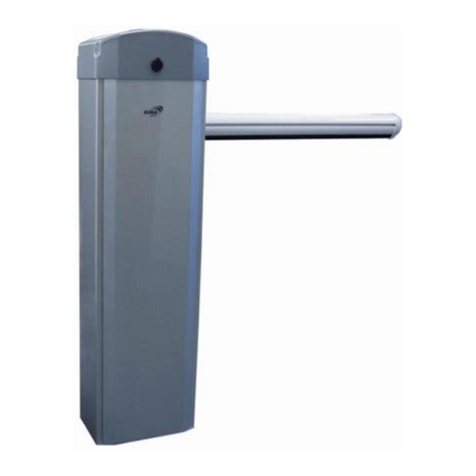
PPA JETFLEX User manual

¡ATTENTION!
Do not use this equipment
without rst reading the
User’s Manual.
JETFLEX NON-STOP
AUTOMATIC BARRIER
Technical Manual
P31493 - 08/2022
Rev. 0
All images in this manual are for illustrative purposes only.
Manufactured by: Motoppar Indústria e Comércio de Automatizadores Ltda
Av. Dr. Labieno da Costa Machado, 3526 - Distrito Industrial - Garça - SP - CEP 17406-200 - Brasil
CNPJ: 52.605.821/0001-55
www.ppa.com.br | +55 14 3407 1000

3
INSTALLATION LOCATION
The location where the barrier will be inalled mu be previously analyzed,
including the entire site infraructure, oor conditions, electrical power
supply, passageway width, ceiling height (if any), vehicle ow and the need
to use optional accessories.
Once it is analyzed, the equipment that be ts the needs of the place
should be chosen.
NOTE: Using articulated barriers is usually recommended in places with
low ceilings. In this case, contact the factory to have a barrier with the
proper size for inallation in the specic location supplied.
IMPORTANT
Check if any obacles could interfere with the complete barrier
opening and closing. If so, the equipment inallation will be impaired,
and repairs to the local infraructure will be necessary. Carefully
choose the model according to its technical features and where it will
be inalled. Notice the need for optional accessories. Calculate the
ow of vehicles on site.
NOTE: If the oor does not meet the above specications, a concrete
base plate respecting the cabinet base dimensions mu be provided to
x the cabinet. The concrete base plate should be inalled at a minimum
height of 100 mm from the ground.
Preparing the location:
1. Run a 3/4" conduit pipe through the oor or concrete base plate from
the center of the base to the circuit breaker box inalled from where the
equipment's electrical supply will come.
2. Run the power and pushbutton cables through this pipe to where the
equipment will be operated. Check the table below to choose the cables
according to the NBR 5410 andard.
TABLE OF CONTENTS
Installation location.......................................................................................................................................................................................................3
General features................................................................................................................................................................................................................4
Technical Specifications............................................................................................................................................................................................5
Equipment dimensions..............................................................................................................................................................................................5
Building the base plate to install the cabinet.........................................................................................................................................6
Installing the barrier .....................................................................................................................................................................................................7
Balancing the barrier and checking the belt........................................................................................................................................12
Adjusting the magnet bars..................................................................................................................................................................................13
Operation............................................................................................................................................................................................................................14
TRIFLEX CONNECT AC control board ..................................................................................................................................................14
Encoder system (Digital Reed).........................................................................................................................................................................14

4 5
Motor power supply Cable type and size
110V 1 PP cable - 2 x 2.5 mm
220V 1 PP cable - 2 x 2.5 mm
220V 1 PP three-phase cable - 3 x 2.5 mm
380V 1 PP three-phase cable - 4 x 2.5 mm
NOTE: If accessories are used, provide piping and cables as needed.
Provide a grounding rod that will be xed close to the body of the gate.
GENERAL FEATURES
• Universal cabinet that allows inalling the barrier arm on either side of
the barrier.
• Concealing syem for manual unlocking (up to 4.5m).
• Electronic control unit with frequency inverter.
• Mechanical op with height adjument.
• Syem activation through a gearmotor, pulleys, and belts.
• Galvanized eel cabinet with anti-corrosion treatment and electroatic
painting guarantee excellent resiance again the action of time.
• Limit switch syem with encoder.
• Electronic brake.
• Allows inalling several accessories (inductive loop, signal light,
photocell, pushbutton, etc.).
TECHNICAL SPECIFICATIONS
Non-op barrier (linear)
Barrier length Cycles/hour
Opening
time
(adjuable)
Closing
time
(adjuable)
Voltage Gearbox
2.5 to 3m 1200 0.7 second
(minimum) 0.7 second
(minimum) 127 and
220 V
Oil bath
method
Non-op barrier (articulated)
Barrier length Cycles/hour
Opening
time
(adjuable)
Closing
time
(adjuable)
Voltage Gearbox Barrier prole
3m (maximum) 580 0.7 second
(minimum) 0.7 second
(minimum) 127 and
220 V
Oil bath
method Rectangular
60 x 30mm
EQUIPMENT DIMENSIONS
FRONT OF THE BARRIER
INSPECTION DOOR

67
OBS: Measurements in mm. The base plate mu be leveled to allow the
equipment to perform better.
INSTALLING THE BARRIER
1. When xing the barrier, notice that the cabinet inspection door mu
face the side of the road or vehicle passage.
76 mm (3")
BUILDING THE BASE PLATE TO INSTALL THE
CABINET
Build a concrete base so that the highlighted direction (350) faces the curb
(reet, passing vehicles) according to the suggeed dimensions.
Cover
Barrier Base
Articulated barrier prole
(EXTRA) 180 mm
USEFUL LENGTH = BARRIER LENGTH -180 mm
(BARRIER LENGTH + 110 mm)
(Ground clearance)
Barrier xing deduction 283 mm
Useful length = Barrier length -283 mm
Barrier length
¾” CONDUIT PIPE
(MINIMUM) FOR THE
CABLES POSITIONED IN
THE CENTER OF THE BASE
INSPECTION DOOR
VEHICLE PASSAGE
Linear barrier prole
CURB USEFUL HEIGHT
210 (OPENING DEDUCTION)
30 (SAFETY MARGIN)
OPEN BARRIER HEIGHT
DISTANCE FROM BARRIER BASE TO COVER
GROUND CLEARANCE AT BARRIER BASE
(FIXING – DEDUCT FROM THE BARRIER LENGTH 280 mm)

8 9
2. Position / align the cabinet on the base and mark the holes so that the
front of the gate (inspection door side) faces the curb (reet, passage
of vehicles).
3. Remove the cabinet from the base and drill holes in the previously
marked locations.
OBS: Make 04 holes with a Ø10mm drill and at lea 80-mm deep.
4. Insert the anchor bolts in the holes of the base, as shown below.
OBS: The anchor bolts mu not be inserted thoroughly. They mu be
approximately 15 mm above the base.
5. Position the cabinet over the base, and t the cabinet holes into the
anchor bolts
6. Recheck the cabinet alignment. If necessary, move it circularly as desired.

10 11
7. Insert the washers and nuts to x the cabinet.
8. Insert the barrier/arm into the xing assembly housing, and align the
mounting holes.
9. After positioned, tighten the nut and the screw.
10. Power/energize the barrier according to the purchased product voltage
(127V or 220V).
OBS: Use 2.50mm² wires. Use a dedicated circuit breaker, that is, a circuit
breaker where only the barrier will be connected.
11. Check/set the barrier alignment (opening and closing). Use mechanical
ops for this situation and move them as necessary.
12. The barrier will be in good working conditions when closing when
the barrier/arm follows the requirements shown below in the image.
WASHERS
AND NUTS
OPENING AND CLOSING
ADJUSTMENT STOPS
BARRIER / ARM
ASSEMBLED BARRIER
/ LANCE
TIGHTENING NUT
AND SCREW
SCREW
MOUNTING
HOLES
NUT

12 13
13. The barrier will be in good working order when opening when the
barrier/arm follows the requirements shown below in the image.
OBS: It is not necessary to rebalance the barrier, as it leaves the factory
balanced. However, if necessary, follow the guidelines below.
BALANCING THE BARRIER AND CHECKING
THE BELT
1. Remove the gearmotor from the cabinet, leave the belt free, and
check if the barrier remains at approximately 45°. Otherwise, adju it
through the spring screw by loosening or tightening it until nding
the ideal adjument.
2. Once adjued, replace the gearmotor and the belt, and check if the
belt is well tensioned and ready for operation. With your thumb,
apply even pressure on the belt. If it does not bend, it is because it is
well-tensioned. If the belt is loose, adju it through the belt tensioner
screws, using a wrench according to the respective nut.
ADJUSTING THE MAGNET BAR
After the barrier is balanced correctly and adjued in the opening and
closing “mechanical ops”, check if the magnet bars need adjuing.
1. Keep the barrier in the open position (90°).
2. Adju the magnet bar so the la magnet is in front of the Sensor Hall
(Encoder), and tighten the xing screws.
OBS: Follow the same procedure with the barrier in the closing position
(0°).
The barrier is ready to work. Turn on the circuit breaker, press the “+”
button on the electronic board, and the barrier will move.
BELT
Magnet bar
Hall sensor
BELT
TENSIONERS
SPRING SCREW

14
OBS: On the r activation, the barrier will move slowly in the opening
and closing directions as it reads the path. Soon after the reading, the
operation is normalized and will art operating at the factory default
speed. For more accurate adjuments, refer to the electronic board
options.
OPERATION
The barrier is operated by a micro-controlled control board, activated via
remote control or any other device that provides a NO (Normally Open)
contact.
TRIFLEX CONENCT AC CONTROL BOARD
The control board operates with a frequency inverter, which drives the
three-phase induction motor from a single-phase AC power supply and a
logic controller to carry out the inverter operations. For more information,
refer to the TRIFLEX CONNECT AC control unit manual.
ENCODER SYSTEM (DIGITAL REED)
An encoder monitors the barrier position. Also called Digital Signal
Angular Positioning Transducer Syem, it is used to precisely control and
monitor the gearmotor movements.
Therefore, there is the possibility of recording certain gate positions in
the memory and enabling the control board to control opening and
closing. This is done by employing sensors that inform the barrier travel
direction and position during operation.
Thus, it is a device responsible for the barrier path's reading, memorization,
and accuracy.
Table of contents
Other PPA Automatic Barrier manuals