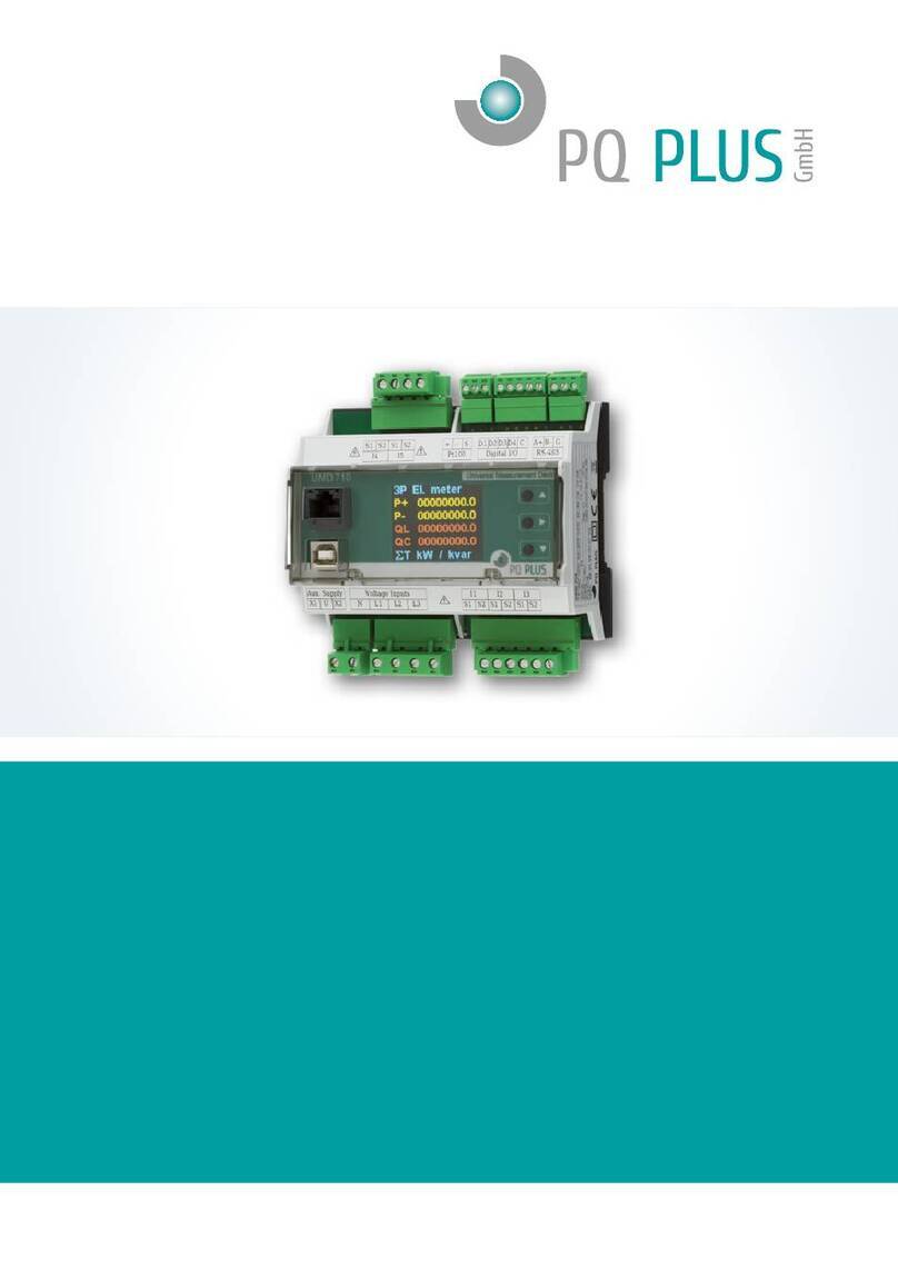
PQ Plus MMU 3 Instruction manual

• •
Quick-Start Anleitung
Quick-Start Manual
MMU 3 / MMI 12
Deutsch / English

PQ Plus – MMU / MMIQuick-Start Anleitung
2
DE
Inhaltsverzeichnis
Installation................................................................................................4
Montage .......................................................................................................4
Spannungsversorgung .................................................................................4
Spannungsmessung ....................................................................................5
Stromwandler anschließen ..........................................................................6
RS485-Schnittstelle .....................................................................................6
Local Bus-Schnittstelle .................................................................................6
Inbetriebnahme...................................................................................... 7
Werksseitige Kommunikationseinstellungen ................................................7
Verbindung mit einem PC herstellen ............................................................7
MMU kongurieren .......................................................................................8
MMI kongurieren ........................................................................................9
Anschluss und Einstellungen kontrollieren ................................................10
Technische Daten................................................................................. 11
Eine ausführliche Anleitung nden Sie auf unserer Homepage unter:
https://www.pq-plus.de/medien-downloads/

PQ Plus – MMU / MMI
3
EN
Quick-Start Anleitung
Table of Contents
Installation...............................................................................................12
Mounting.....................................................................................................12
Voltage supply ............................................................................................12
Voltage measurement.................................................................................13
Connecting a current transformer...............................................................14
RS485 interface..........................................................................................14
Local Bus interface.....................................................................................14
Commissioning...................................................................................... 15
Factory communication settings.................................................................15
Connecting to a PC ....................................................................................15
Conguring the MMU..................................................................................16
Conguring the MMI ...................................................................................17
Checking the connection and settings........................................................18
Technical data....................................................................................... 19
You can nd detailed instructions on our website at:
https://www.pq-plus.de/en/media-downloads/

Quick-Start Anleitung
4
DE
Installation
Montage
Das MMU 3 und das MMI 12 sind für eine Montage auf der DIN-Hutschiene
vorgesehen.
RS-485
A+ B- G Cat5e
Local Bus
L1
L2
L3
Voltage Inputs
N
PWR SYN
XR XT
PWR
X1 X2
RWP NYS
RX TX
CAT III
300 V
89.7
92.8
98.0
53.6
Cat5e
Local Bus
I4 I5 I6
I7 I8 I9
I10 I11 I12
Current Inputs
I1 I2 I3
RX TXPWR SYN
Cat5e
Local Bus
PWR
SN: 123
SYN
RX TX
62.2
11.0
45.0
67.5
89.7
93.4
98.0
53.6
Spannungsversorgung
Das MMU 3 benötigt folgende Spannungsversorgung:
12 … 26 VDC
Die Anschlüsse hierfür benden sich oben links am MMU und sind mit
PWR „X1“ und „X2“ beschriftet. Für die Absicherung der Spannungsversor-
gung wird ein 1 A Leitungsschutzschalter empfohlen.

Quick-Start Anleitung PQ Plus – MMU / MMI
5
DE
Das MMI 12 versorgt sich über den Local Bus (Verbindung mittels
Patch-Kabel). Die Spannung liefert das vorgelagerte MMU oder ein an-
deres Mastergerät mit Local Bus-Anschluss und kann zu weiteren MMI’s
verteilt werden. Die Anschlüsse hierfür benden sich oben rechts und oben
links am MMI und sind mit „Local Bus“ beschriftet.
L1
24V DC
L2
L3
N
RX TXPWR SYN
Cat5e
Local Bus
Cat5e
Local Bus
PWR
SN: 126
SYN
RX TX
I4 I5 I6
I7 I8 I9
I10 I11 I12
Current Inputs
I1 I2 I3
RX TXPWR SYN
Cat5e
Local Bus
Cat5e
Local Bus
PWR
SN: 127
SYN
RX TX
I4 I5 I6
I7 I8 I9
I10 I11 I12
Current Inputs
I1 I2 I3
RS-485
A+ B- G Cat5e
Local Bus
L1
L2
L3
Voltage Inputs
N
PWR SYN
XR XT
PWR
X1 X2
SYNPWR
RX TX
CAT III
300 V
RS485
Spannungsmessung
Das MMU 3 verfügt über 3 Spannungseingänge welche sowohl für eine
direkte als auch für eine Wandlermessung geeignet sind. Die Phasenspan-
nungen werden über die Klemmen L1, L2, L3 und den gemeinsamen Neut-
ralleiteranschluss N gemessen.
Es wird empfohlen, die Spannungspfade mit einem 1 A Leitungsschutz-
schalter abzusichern.

Quick-Start Anleitung
6
DE
Stromwandler anschließen
Die MMI‘s sind nicht für eine direkte Strommessung ausgelegt. Die An-
schlüsse der benötigten Stromwandler benden sich auf der Unterseite des
MMI‘s und sind folgendermaßen beschriftet:
•F1 für das Anschlusskabel der Ströme 1 - 3
•F2 für das Anschlusskabel der Ströme 4 - 6
•F3 für das Anschlusskabel der Ströme 7 - 9
•F4 für das Anschlusskabel der Ströme 10 - 12
Die Stromeingänge der MMI‘s sind für Sekundärsignale von 333 mV
ausgelegt und mit RJ12-Anschlussbuchsen ausgestattet.
Hinweis zum Anschluss der Kabelumbaustromwandler:
•Adernpaare: Phase 1 = Braun; Phase 2 = Schwarz; Phase 3 = Grau
•Anschluss: Ader auf S1 (k): Grau, Grün, Weiß
Ader auf S2 (l): Rosa, Gelb, Braun
RS485-Schnittstelle
Das MMU 3 ist mit einer RS485-Schnittstelle ausgestattet, die über das
Modbus RTU-Protokoll kommuniziert. Die Anschlüsse benden sich oben
am Gerät und sind mit „A+“, „B-“ und „G“ beschriftet.
Local Bus-Schnittstelle
Das MMU 3 ist rechts oben, das MMI 12 rechts und links oben zusätzlich
mit RJ45-Anschlüssen für den Local Bus ausgestattet. Über diese Schnitt-
stelle ndet die interne Kommunikation statt.

Quick-Start Anleitung PQ Plus – MMU / MMI
7
DE
Inbetriebnahme
Werksseitige Kommunikationseinstellungen
Das MMU 3 wird standardmäßig mit der Geräteadresse 1 und einer Baud-
rate von 9600 Baud für die serielle Schnittstelle ausgeliefert.
Die MMI 12 werden über die Software ENVIS.Daq am MMU 3 konguriert
und erhalten Geräteadressen ab 200.
Verbindung mit einem PC herstellen
Um das MMU 3 mit einem PC zu verbinden, können Sie entweder einen
Schnittstellenkonverter (z.B. RS485 auf USB) oder ein Mastergerät als
Gateway verwenden.
Konverter: Für diese Verbindung muss der dazugehörige USB-Treiber des
Schnittstellenkonverters auf dem PC installiert sein.
Gateway: Wenn Sie sich per LAN-Kabel mit einem Mastergerät verbinden
möchten, müssen Sie entweder die IP-Adresse des Gerätes auf Ihr Netz,
oder die IP-Adresse Ihres PC´s anpassen. Alle PQ Plus Universalmessge-
räte mit Ethernetschnittstelle werden mit der IP: 10.0.0.1 ausgeliefert.
•Öffnen Sie die ENVIS.Daq und wählen für den Schnittstellenkonverter den
Punkt „COM“ und für das Mastergerät den Punkt „TCP“. (Für die Verbin-
dung an einem Mastergerät muss in diesem das Gateway aktiviert sein.)

Quick-Start Anleitung
8
DE
•Öffnen Sie das Dropdown-Menü und wählen die COM-Schnittstelle aus
oder tragen die IP-Adresse des Mastergerätes und den dazugehörigen
Port (Standard 4001) in die dafür vorgesehenen Felder ein.
•Mit einem Klick auf „Verbinden“ wird die Verbindung zum Gerät hergestellt.
Hier können Sie alle weiteren Einstellungen des Gerätes vornehmen.
MMU konfigurieren
Nachdem die Verbindung mit dem MMU erfolgreich hergestellt wurde, kann
es über den Button „Konguration“ konguriert werden.
Unter dem Register „Install“ kann die Spannungsmessung konguriert
werden.
Nennspannung, Netzform, Spannungswandler, …

Quick-Start Anleitung PQ Plus – MMU / MMI
9
DE
MMI konfigurieren
Im Reiter „Local Bus“ werden die Module die über die RJ45-Verbindung am
MMU angeschlossen sind konguriert.
1. Erkannte, aber nicht kongurierte Slaves
Hier werden alle (max. 5) MMI‘s angezeigt, welche über den Local Bus
verbunden, aber noch nicht im UMD konguriert sind.
2. MMI zuweisen
D1 – D5 sind die verfügbaren Plätze am Local Bus, die mit MMI’s belegt
werden können. Unter „Parameter“ kann das jeweilige Modul durch Aus-
wahl der Seriennummer hinzugefügt und ein Name vergeben werden.
3. Kongurationsansicht aktualisieren
Nachdem mit dem Button “Senden” die Konguration an das Gerät
übertragen wurde, wird die Kongurationsansicht über den Button
“Empfangen” aktualisiert.
4. Stromeingang wählen
F1 – F4 sind die jeweiligen 3-phasigen Eingänge am MMI.
Unter „Parameter“ können diese aktiviert und konguriert werden.
5. Geräteadresse
Die einzelnen Geräteadressen der MMI Eingänge beginnen
voreingestellt ab 200, somit hat das erste Modul die Adressen
von 200 (F1) – 203 (F4).
Hinweis: Die Aufzeichnung der Local Bus-Daten muss im jeweiligen Mas-
tergerät konguriert werden.

Quick-Start Anleitung
10
DE
Anschluss und Einstellungen kontrollieren
Der Anschluss und die Einstellungen des Messgerätes können nun
über die LiveDaten in der ENVIS.Daq kontrolliert werden.
•Anhand der Stromanzeige kann die Plausibilität überprüft werden. Falls
Sie die Stromstärke nicht kennen, wird empfohlen die Stromstärke mit
einer Stromzange zu vergleichen.
•Bei der Anzeige der einzelnen Wirkleistungen wird Bezug ohne Vorzei-
chen und Lieferung mit negativem Vorzeichen angezeigt. So kann der
richtige Einbau und Anschluss der Stromwandler überprüft werden.
•Über das Zeigerdiagramm kann das Drehfeld und die Zuordnung der
Strom- und Spannungspfade kontrolliert werden. Achten Sie hierbei auf
die Phasenverschiebung von Strom und Spannung.

Quick-Start Anleitung PQ Plus – MMU / MMI
11
DE
Technische Daten
Spannungsversorgung MMU 3: 12 … 26 VDC
MMI 12: über Local Bus
Spannungsmessung 8 … 350 VLN; 14 … 610 VLL
Frequenz 40 … 70 Hz
Abtastrate 6,4 kHz
Leistungsaufnahme 1,5 W / Modul
Umgebungstemperatur TBetrieb -25 ... 60 °C
Schutzart Front / Rückseite IP40 / IP20
EMV Klasse A: Industriebereich nach IEC 61326-1
Überspannungskategorie CAT III / 300 V
Überlast (permanent) U: 1355 VLN | I: 666 mVAC
Überlast (1s) U: 2140 VLN | I: 3,33 VAC
Mechanische Daten
Montage 35 mm DIN Schiene
Maße BxHxT 54 x 94 x 61 mm
Gewicht Ca. 110 g / Modul
Max. Anzahl Abgänge pro MMI 4x 3-phasig / 3x 3-phasig + N / 12x 1-phasig
Max. Anzahl Module MMU 3: 1 / MMI 12: 5
Schnittstellen
RS485 2400 … 921600 Baud
Protokolle Modbus RTU

PQ Plus – MMU / MMIQuick-Start Manual
12
EN
Installation
Mounting
The MMU 3 and the MMI 12 are intended for mounting on the DIN rail.
RS-485
A+ B- G Cat5e
Local Bus
L1
L2
L3
Voltage Inputs
N
PWR SYN
XR XT
PWR
X1 X2
RWP NYS
RX TX
CAT III
300 V
89.7
92.8
98.0
53.6
Cat5e
Local Bus
I4 I5 I6
I7 I8 I9
I10 I11 I12
Current Inputs
I1 I2 I3
RX TXPWR SYN
Cat5e
Local Bus
PWR
SN: 123
SYN
RX TX
62.2
11.0
45.0
67.5
89.7
93.4
98.0
53.6
Voltage supply
The MMU 3 requires the following voltage supply:
12 … 26 VDC
The connections for this are placed at the upper left of the MMU and la-
belled PWR “X1" and “X2". It is recommended to protect the voltage supply
with a 1 A circuit breaker.

PQ Plus – MMU / MMI
13
EN
The MMI 12 uses the Local Bus as supply (connection by patch cable). The
voltage is provided by the upstream MMU or another master device with
Local Bus connection. It can be distributed on to further MMIs. The connec-
tions for this are located at the upper right and left of the MMI and labelled
as "Local Bus".
L1
24V DC
L2
L3
N
RX TXPWR SYN
Cat5e
Local Bus
Cat5e
Local Bus
PWR
SN: 126
SYN
RX TX
I4 I5 I6
I7 I8 I9
I10 I11 I12
Current Inputs
I1 I2 I3
RX TXPWR SYN
Cat5e
Local Bus
Cat5e
Local Bus
PWR
SN: 127
SYN
RX TX
I4 I5 I6
I7 I8 I9
I10 I11 I12
Current Inputs
I1 I2 I3
RS-485
A+ B- G Cat5e
Local Bus
L1
L2
L3
Voltage Inputs
N
PWR SYN
XR XT
PWR
X1 X2
SYNPWR
RX TX
CAT III
300 V
RS485
Voltage measurement
The MMU 3 has 3 voltage inputs that are suitable for both direct and
current transformer measurements. The phase voltages are measured via
terminals L1, L2, L3 and the common neutral conductor connection N.
It is recommended to protect the voltage paths with a 1 A circuit breaker.

PQ Plus – MMU / MMIQuick-Start Manual
14
EN
Connecting a current transformer
The MMIs are not designed for direct current measurement. The connec-
tions of the required current transformers are located on the bottom of the
MMI and labelled as follows:
•F1 for the connection cable of currents 1 - 3
•F2 for the connection cable of currents 4 - 6
•F3 for the connection cable of currents 7 - 9
•F4 for the connection cable of currents 10 - 12
The current inputs of the MMIs are designed for secondary signals of
333 mV and equipped with RJ12 connection sockets.
Notice on connection of the cable conversion current transformers:
•Wire pairs: Phase 1 = brown; phase 2 = black; phase 3 = grey
•Connection: Wire to S1 (k): Grey, green, white
Wire to S2 (l): Pink, yellow, brown
RS485 interface
The MMU 3 is equipped with an RS485 interface that communicates via
the Modbus RTU protocol. The connections are located on the top of the
device and labelled "A+", "B-", and "G".
Local Bus interface
The MMU 3 is additionally equipped with RJ45 connections for the Local
Bus at the upper right, the MMI 12 at the upper right and left. This interface
provides internal communication.

PQ Plus – MMU / MMI
15
EN
Commissioning
Factory communication settings
The MMU 3 is delivered by default with the device address 1 and a baud
rate of 9600 Baud for the serial interface.
The MMI 12 are congured via the ENVIS.Daq software at the MMU 3 and
assigned device addresses starting at 200.
Connecting to a PC
You can either use an interface converter (e.g., RS485 to USB) or a master
device as gateway to connect the MMU 3 to a PC.
Converter: The associated USB driver of the interface converter must be
installed on the PC for this.
Gateway: If you want to connect to a master device by LAN cable, you
need to either adjust your device's IP address to your network or the IP ad-
dress of your PC. All PQ Plus universal measurement devices with Ethernet
interface are delivered with the IP: 10.0.0.1.
•Open the ENVIS.Daq and select the item "COM" for the interface convert-
er and the item "TCP" for the master device. (The gateway must be
enabled at the master device to connect to it.)

PQ Plus – MMU / MMIQuick-Start Manual
16
EN
•Open the drop-down menu and select the COM interface or enter the
IP address of the master device and the associated port (default: 4001)
in the elds provided for this.
•Clicking “Connect” establishes a connection to the device.
You can make all further settings of the device here.
Configuring the MMU
Once the connection to the MMU has been successfully established, it can
be congured with the "Conguration" button.
You can congure the voltage measurement under the tab "Install".
Nominal voltage, network conguration, voltage transformer, …

PQ Plus – MMU / MMI
17
EN
Configuring the MMI
The modules connected to the MMU via the RJ45 connection are cong-
ured in the tab "Local Bus".
1. Detected but not Congured Slaves
All (max. 5) MMIs that are connected via the Local Bus but not yet
congured in the UMD are displayed here.
2. Assigning MMI
D1 – D5 are the available slots on the Local Bus that can be occupied
with MMIs. Under “Parameter”, the respective module can be added by
selecting the serial number and a name can be assigned.
3. Update conguration view
After the conguration has been transmitted to the device via the button
“Send”, the conguration view is updated via the button “Receive”.
4. Selecting current input
F1 – F4 are the respective 3-phase inputs at the MMI.
They can be activated and congured under “Parameter”.
5. Device address
The individual device addresses of the MMI inputs start from 200 by
default. The rst module thus has the addresses
from 200 (F1) – 203 (F4).
Notice: Recording of the Local Bus data must be activated in the respec-
tive master device.

PQ Plus – MMU / MMIQuick-Start Manual
18
EN
Checking the connection and settings
The connection and the settings of the universal measurement device
can now be reviewed via the “Act Data” in the ENVIS.Daq.
•The display of the currents can be used to review plausibility. If you do
not know the current, we recommend comparing the current with a cur-
rent clamp.
•When displaying the individual active powers, consumption is displayed
without a prex and supply with a negative prex. This permits verication
of the correct installation and connection of the current transformers.
•The pointer diagram in the ENVIS.Daq can be used to check the rotating
eld and assignment of the current and voltage paths. Observe the phase
shift of current and voltage for this.

PQ Plus – MMU / MMI
19
EN
Technical data
Voltage supply MMU 3: 12 … 26 VDC
MMI 12: via Local Bus
Voltage measurement 8 … 350 VLN; 14 … 610 VLL
Frequency 40 … 70 Hz
Sampling rate 6.4 kHz
Power consumption 1.5 W / module
Ambient temperature Toperation -25 ... 60 °C
Protection type front / rear IP40 / IP20
EMC Class A: Industrial area according to
IEC 61326-1
Overvoltage category CAT III / 300 V
Overload (permanent) U: 1355 VLN | I: 666 mVAC
Overload (1s) U: 2140 VLN | I: 3.33 VAC
Mechanical data
Mounting 35 mm DIN rail
Dimensions WxHxD 54 x 94 x 61 mm
Weight Approx. 110 g / module
Max. number of outputs per MMI 4x 3-phase / 3x 3-phase + N / 12x 1-phase
Max. number of modules MMU 3: 1 / MMI 12: 5
Interfaces
RS485 2400 … 921600 baud
Protocols Modbus RTU

PQ Plus GmbH
Hagenauer Straße 6
D-91094 Langensendelbach
Tel. / Phone: (+49) 9133-60640-0
Fax: (+49) 9133-60640-100
Email: [email protected]
Internet: http://www.pq-plus.de
Geschäftsführer / Managing director:
Daniel Fierus-Beyer
Umsatzsteuer Identikationsnummer / VAT ID:
DE 301 767 284
Weitere Informationen und den aktuellen Katalog nden Sie bei
uns im Internet.
For further information and the current catalogue, see our website.
https://www.pq-plus.de
Stand / As of: 2023.07
Technische Änderungen vorbehalten.
Technical changes reserved.
This manual suits for next models
1
Table of contents
Languages:
Other PQ Plus Measuring Instrument manuals
PQ Plus
PQ Plus UMD 807 E User manual

PQ Plus
PQ Plus MMD 98 Instruction manual

PQ Plus
PQ Plus UMD 703 Instruction manual

PQ Plus
PQ Plus UMD 710A Instruction manual

PQ Plus
PQ Plus UMD 97 Instruction manual
PQ Plus
PQ Plus UMD 705 Instruction manual

PQ Plus
PQ Plus UMD 701 User manual

PQ Plus
PQ Plus UMD 707 Instruction manual
PQ Plus
PQ Plus UMD 705 User manual

PQ Plus
PQ Plus CMD 68-54 Instruction manual