EG&G SOLOIST-U0300 Service manual

SOL
OISTTM
Alpha
Spectrometer
Operating
and
Servíce
Manual
p
lele
Printed
in
U.S.A.
EG&G
ORTEC
Part
No.
740180
4111
0693
Manual
Revision
A

SOLOIST,
ULTRA-AS,
ULTRA, ALPHAMAT,
and
Ruggedized are
trademarks
of
EG&G
ORTEC.
®Microdot
is
a
registered
trademark
of
Malco/Microdot.
®Swagelok
is
a
registered
trademark
of
Crawford
Company.

III
CONTENTS
WARRANTY.
v
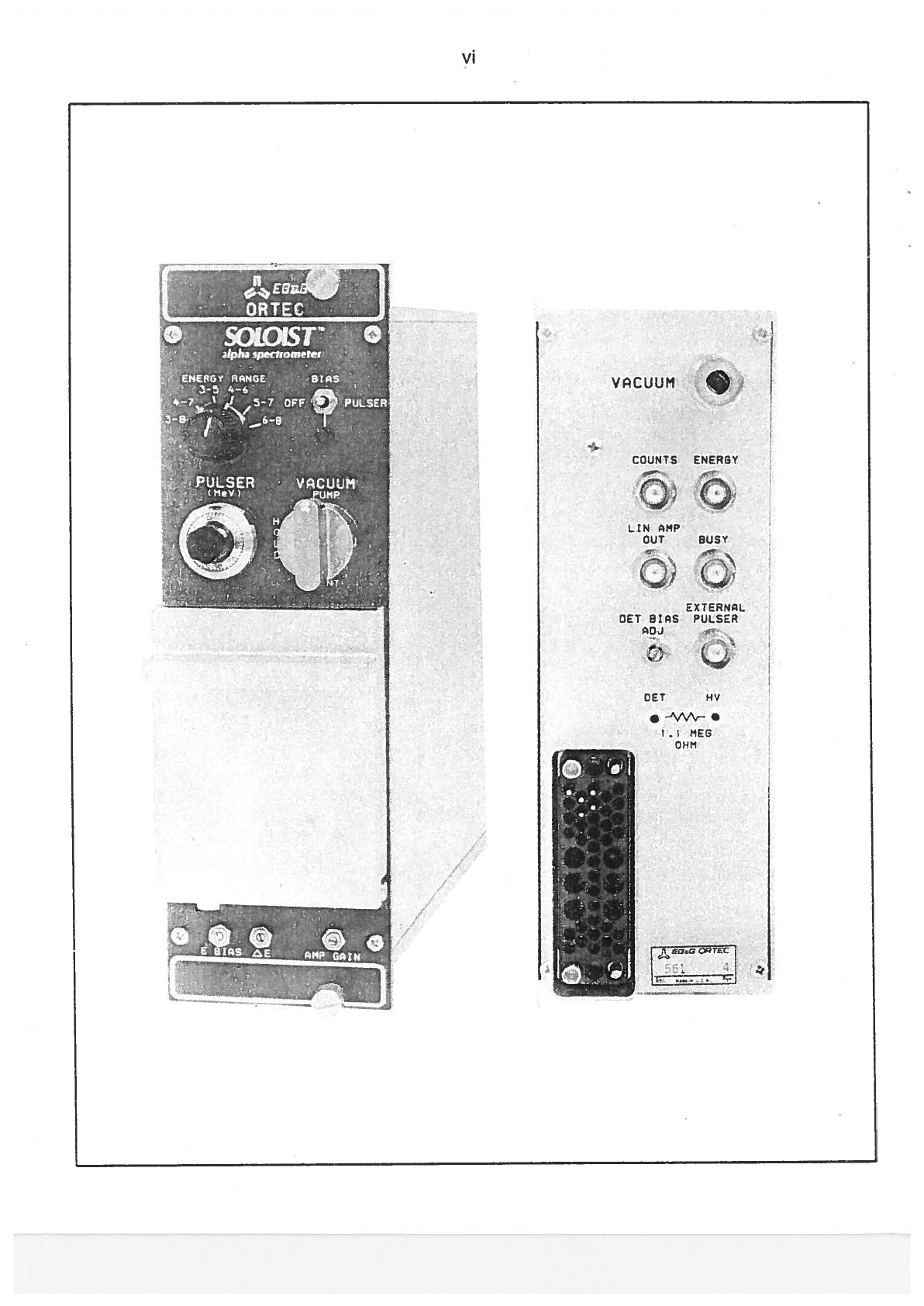
PHOTOGRAPH
vi
1.
DESCRIP1YON
1
2,
SPECIFICATIONS
2.1. PERFORMANCE
2.2.
VACUUM
CHAMBER
2.3.
CONTROLS
2.4.
INPUTS
2.5. OUTPUTS
2.6.
ELECTRICAL
AND
MECHANICAL
2.7.
ACCESSORIES
3
3
3
3
4
4
4
4
6
6
7
7
8
8
8
4.
OPERATION
4.1.
OPERATING
PUMP/HOLDNENT
VALVE
4.2.
SAMPLE
INSER1iON
4.3.
RESOLUTION
MEASUREMENI
AND
CALIBRATION
5.
THEORY
OF
OPERATION
5.1.
SOLOIST
ALPHA
SPECTROMETER
.INEAR
AMPLIFIER
SCHEMATIC.
6.
MAINTENANCE
AND
SERVICE
6.1.
DECONTAMINATION
6.2.
SOLOIST
CHAMBER
REMOVAL
AND
REPLACEMENT.
6.3.
TROUBLESHOOTING
GUIDE
PRINTED
WIRING
BOARD
(PWB)
ASSEMBLY
DRAWINGS
729890
-
ALPHA
SPECTROMETER
729940
-
LINEAR
AMPLIFIER
SCHEMATTCS
761250
-
ALPHA
SPECTROMETER
764030
-
LINEAR
AMPLIFIER
Fig.
1.1.
Fig.
3.1.
Fig.
3.2.
Fig.
3.3.
Fig.
4.1.
Fig.
5.1.
Fig.
6.1.
1
6
7
8
9
11
14
3.
INSTALLATION
3.1.
DETECTOR
SETUP
3.2.
CONNECTION
TO
POWER
3.3.
VACUUM
CONNECTION
3.4.
SIGNAL
CONNECTIONS
3.5.
ENERGY OUTPUT
FULL-SCALE
ADJUSTMENT
(Other than
10
V).
3.6.
LINEAR
AMP
OUTPUT
FULL-SCALE
ADJUSTMENT
(Otherthan
70V).
11
12
13
13
13
15
LIST
OF FIGURES
A
Simplified Block
Diagram
of
the
SOLOIST
Electronics
Position
of
Polarity
Switches
for
Bias
and
Amplifier
Suggested
Vacuum
Connections
for
the
SOLOIST
Spectrometer.
SignaI
Connections
PUMP/HOLDNENT
Valve
Detailed
Block
Diagram
of
the
SOLOIST
Alpha
Spectrometer
Vacuum
Chamber
and
Coaxial
Cable
Connection

iv
1
v
Standard
Warranty
for
EG&G
ORTEC
Instruments
EG&G
ORTEC
warrants
that
the
items
wili
be
delivered
free
trom
defects
in
material
or
workmanship.
EG&G
ORTEC
makes
no
other
warranties,
express
or
impiied,
and
specificaiiy
NO
WARRANTY
OF
MERCHANTABILITY
OR
FITNESS
FOR
A
PARTICULAR
PURPOSE.
EG&G
ORTEC’s
exclusive
iiability
is
limited
to
repairing
ar
replacing at
EG&G
ORTEC’s option,
items
found
by
EG&G
ORTEC
to
be
defective
in
workmanshíp
ar
materiais
within
one year
from
the
date
of
deiivery.
EG&G
ORTEC’s
liability
on
any
claim
of
any
kind,
including
negligence,
Ioss,
ar damages
arising out
of,
connected
with,
ar
from
the
performance ar
breach
thereof,
ar
from
the
manufacture,
saie,
deiivery,
resale,
repair,
or
use
of
any
item
ar
services
covered
by
this
agreement
or
purchase
arder,
shaii
in
no
case
exceed
the
price
aliocabie
ta
the
tem
ar
service
furnished
ar
any part thereof
that
gives
rise
to
the
claim.
in
the
event
EG&G
ORTEC
faiis
to
manufacture
ar
deliver
items cailed
for
in
this
agreement
or
purchase
arder,
EG&G
ORTEC’s
exclusive
liability
and
buyer’s
exclusive remedy
shail
be
release
of
the
buyer
fram
the
obligation
to
pay
the
purchase
price.
in
no
event
shail
EG&G
ORTEC
be
liable for
speciai
ar
consequential
damages.
Quality
Control
Before
being
approved
for
shipment,
each
EG&G
ORTEC
instrument must
pass
a
stringent
set
of
quality
contrai
tests
designed
to
expose
any
flaws
in
materiais
ar
workmanship.
Permanent
records
of
these
tests
are
maintained
for
use
in
warranty
repair
and
as
a
saurce
ot
statisticai
information
for
design
impravements.
Repair
Service
if
it
becomes necessary
to
return this
instrument
for
repair,
it
is
essential
that
Customer
Services
be
cantacted
in
advance
of
its
return
so
that
a
Return Authorization
Number can
be
assigned
ta
the
unit.
Also,
EG&G
ORTEC
must be
informed,
either
in
writing,
by
teiephone
[(615)
482-4411],
by
telex
(6843140)
ar
by
facsimiie
transmissian
[(615)
483-0396],
af
the
nature
af
the
fauit
aí
the
instrument
being
returned
and
af
the
model,
serial,
and
revisian
(“Rev’
on
rear
panei)
numbers.
Failure
to
do
so
may
cause
unnecessary
deiays
in
getting
the
unit
repaired.
lhe
EG&G
ORTEC
standard
procedure
requires
that
instrurnents returned
for
repair
pass
the
sarne
quaiity
contrai
tests
that
are
used
for
new
praductian instruments.
instruments
that
are
returned
should
be
packed
sa
that
they
wiii
withstand
nor
mal
transit
handiing and
must
be
shipped
PREPAID
via
Air
Parcei
Post
ar
Uníted
Parcei
Service
to
the
nearest
EG&G
ORTEC
repair
center. The
address
iabei
and the
package
shauid
inciude
the
Return
Authorization
Number
assigned.
instruments
being
returned
that
are
damaged
in
transit
due
to
nade
quate
packing
wiii
be
repaired
at
the
sender’s
expense,
and
it
wiii
be the
sender’s
responsibiiity
to
make
ciaim
with
the
shipper. instrurnents
not
in
warranty
wiii
be
repaired at the
standard
charge
unless
they
have
been
grassiy
misused
ar
mishandied,
in
which
case
the
user
will
be
notified
prior
ta the
repair
being
done.
A
quatation
wiii
be
sent
with
the
notitication.
Damage
in
Transit
Shipments shauid
be
examined
immediately upon
receipt
for
evidence
af
externai
ar
canceaied
dam
age.
lhe
carrier
making
deiivery
shouid
be
natitied
immediateiy aí
any
such
damage, since
the
carrier
is
normaiiy
liable
for
damage
in
shipment.
Packing
materiais,
waybiiis,
and
ather
such
documentation
shauid
be
preserved
in
arder
to
estabiish
claims.
After
such
notificatian
to
the
carrier,
please
notify
EG&G
ORTEC
aí
the
circumstances
SO
that
assistance
can
be provided
in
making
damage
claims
and
in
praviding
repiacement
equipment,
if
necessary.
yi
CQUNTS
ENERGV
LIN
AMP
OUT
BUSY
EXTENc
DET
8S
PULSER
OET
NU
•
-•\M—
ME
OHM
VACUUM

1
EG&G
ORTEC
SOLOISTTM
Alpha
Spectrometer
1.
DESCRIPTION
The
SOLOIST
is
an
integrated
spectrometer
for
measuring
low-activity
sampies
that
decay
by
alpha
particle
emission.
lt
incorporates
ali
the
necessary
functions
within
a
NIM-standard
doublewidth
module.
The
module
includes
vacuum
chamber, detector,
bias
supply
for
the
detector,
complete
amplifying
chain
(preamplifier,
amplifier,
and
biased
amplifier),
and
calibration
pulser.
The
SOLOISI
offers
three
flexible
methods
for
recording
the
alpha
emission
activity.
lhe
simplest
is
to
record
the
gross
counting
rate
above
the
2.5-MeV
threshold
using
an
external
counter
and
timer.
lo
achieve
much
lower
detection
Iimits,
the
linear
amplifi
er
output
can
be
fed
to
a
multichannel
puise-height
analyzer
(MCA)
for
quantitative
analysis
of
specific
isotope
peaks
in
the
0-
to
10-MeV
energy
spectrum.
lhe
biased
amplifier
output
of
the
SOLOIST
offers
selection
ot
a
restricted
energy range
(containing
only
the
peaks
of
interest)
for
analysis
on
the
MCA.
lhis
feature
allows a
larger
number
of
aipha
spectrome
ters
to
be
multiplexed
into
the
limited
memory
size
of
asingle
MCA.
A
front-panel
switch
provides
6
seiec
table energy
ranges
at the
biased
amplitier
output
(3
to
8
MeV,
4
to
7
MeV,
3
to
5MeV,
4
to
6
MeV,
5
to
7
MeV,
and
6
to
8
MeV).
Three
front-panei
adjust
ments
permit
precise
calibration
on
any
selected
energy range.
machined
to
dose
tolerances,
before
being
nickel
plated
to
ensure
easy
decontamination.
In
the
event
of
severe
contamination,
the
chamber
may
be
easily
isolated
from
vacuum,
and
then
removed
trom
the
module.
A
compressed,
high-performance
O-ring,
retained
in
a
dove-taiied
groove
in
the
face
of
the
chamber,
provides
an ultra-reliable
vacuum
seal
for
the
chamber
door. Nickel-plated
brass
sample
trays
slide
into
the
chamber
to
provide
an
adjustable
and
precisety
reproducible
sample-to-detector
spacing.
lrays
are
available
to
handle
sample
sizes
from
13 mm
(0.5
ín.)
to
51
mm
(2
in.), with
sample-to
detector
spacing
seiectable
from
1
to
41
mm
in
incre
ments
of
4mm.
lhe
front-panei
PUMP/HOLDNENI
vaive
makes
it
easy
to
insert,
count,
and remove
sam
pies
without
disturbing
the
vacuum
on
other
SOLOIST
chambers
attached
to
the
sarne
vacuum
pump.
A
standard
SwageIok
fitting
on
the
tear
panei
simplifies
connection
ot
the
valve
and
chamber
to
an
externa!
vacuum
pump.
An
optional pump
station
(Modei
576N676A-PPS)
is
available
for
this
function,
and the
Model 576-VM
Vacuum
Manifold
can
be
added
to
connect
up
to
four
SOLOISI
modules
to
the
sarne
vacuum
pump.
lhe
SOLOIST
is
available
with
an
ULIRA-ASTM
Series
detector
instalied.
lhese
ion-implanted
silicon
detectors
from
EG&G
ORTEC
are
specialiy
designed
The
SQLOIST
includes
a
robust,
Iow-background,
sample chamber.
lhe
chamber
is
cast
in
brass,
then
SwageIok
is
a
registered
trademark
of
Crawford
Company.
Busy
LINEAR
AMPLIFIER
OUTPUT
ENERGY
OUTPUT
COUNTS
QUTPUT
Fig. 1.1.
A
SimpHf
leU
Block Diagram
of
the
SOLOIST
Electronics.
2
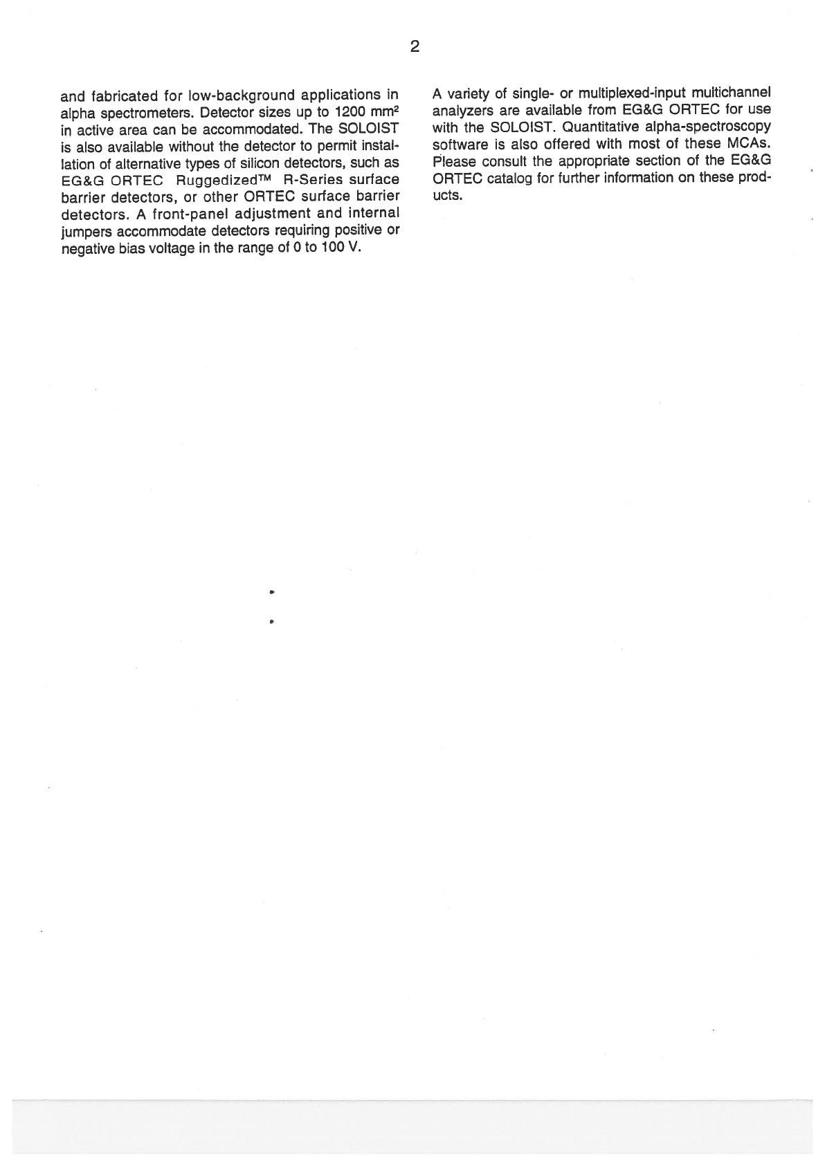
and
fabricated
for
Iow-background
applications
in
alpha
spectrometers.
Detector
sizes
up
to
1200
mm2
in
active
area
can
be
accommodated
The
SOLOIST
is
also
available
without
the
detector
to
permit
instal
lation
of
alternative
types
of
silicon
detectors,
such
as
EG&G
ORTEC
RuggedizedTM
R-Series
surface
barrier
detectors,
or
other
ORTEC
surface
barrier
detectors.
A
front-panel
adjustment
and internal
jumpers
accommodate
detectors
requiring
positive or
negative
bias voltage
in
the
range
of
O
to
100
V.
A
variety
of
single-
or
multiplexed-input multichannel
analyzers
are
available
from
EG&G
ORTEC
for
use
with
the
SOLOIST.
Quantitative
alpha-spectroscopy
software
is
also
offered
with
most
of
these
MCAs,
Please
consult
the
appropriate section
of
the
EG&G
ORTEC
catalog
for
further
information
on
these
prod
ucts.
e
3
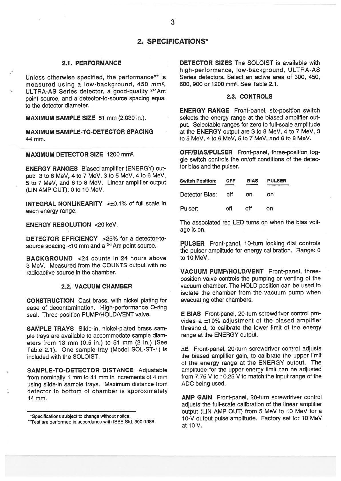
2.
SPECIFICATIONS*
2i.
PERFORMANCE
Unless
otherwise
specified, the
performance**
measured
using
a
low-background,
450
mm2,
ULTRA-AS
Series
detector,
a
good-quaiity
241Arn
point
source,
and
a
detector-to-source
spacing
equal
to
the
detector
diameter.
MAXIMUM
SAMPLE
SIZE
51
mm
(2.030
in.).
MAXIMUM
SAMPLE-TO-DETECTOR
SPACNG
44
mm.
MAXIMUM
DETECTOR
S1ZE
1200
mm2.
ENERGY
RANGES
Biased
amplifier
(ENERGY)
out
put:
3to8MeV,4to7MeV,3to5MeV,4to6MeV,
5
to
7
MeV,
and
6
to
8
MeV.
Linear
amplifier
output
(LIN
ÁMP
OUT):
O
to
10
MeV.
INTEGRAL
NONLINEARITY
<±0.1%
of
fuil
scale
in
each
energy
range.
ENERGY
RESOLUTION
<20
keV.
DETECTOR EFFICIENCY
>25%
for
a
detector-to
source
spacing
<10
mm
and
a
241Am
point
source.
BACKGROUND
<24
counts
in
24
hours
above
3MeV.
Measured
from
the
COUNTS
output
with
no
radioactive
source
in
the
chamber.
2.2.
VACUUM
CHAMBER
CONSTRUCTION
Cast
brass,
with
nickei
plating
for
ease
aí
decontamination.
High-performance
O-ring
seal.
Three-position
PUMP!HOLDNENT valve.
SAMPLE
TRAYS
Slide-in,
nickel-piated
brass
sam
pie
trays
are
available
to
accommodate
sample
diam
eters
from
13
mm
(0.5
in.)
to
51
mm
(2
in.)
(See
Table
2.1).
One sample
tray
(Model
SOL-ST-1)
is
included
with
the
SOLOIST.
SAMPLE-TO-DETECTOR
DISTANCE
Adjustabte
from
nominaIiy
1
mm to
41
mm
in
increments
aí
4
mm
using
slide-in
sample
trays.
Maximum
distance
trom
detector
to
bottom
aí
chamber
is
approximately
44
mm.
*SpecÍfications
subject
to
change
without
notice.
**Test
are
pertormed
in
accordance
with
IEEE
Std.
300-1988.
DETECTOR
SIZES
lhe
SOLOIST
is
available
with
high-performance,
low-background,
ULTRA-AS
Series
detectors. Select
an active
area
of
300,
450,
600,
900
ar
1200
mm2.
See
Table
2.1.
23.
CONTROLS
ENERGY
RANGE
Front-panel,
six-position
switch
selects
the
energy range
at
the
biased
amplifier
out
put.
Selectabie ranges
for
zero
to
fulI-scale
amplitude
at
the
ENERGY
output
are
3
to
8
MeV,
4
to
7
MeV,
3
to
5
MeV,
4
to
6
MeV,
5
to
7
MeV,
and
6
to
8
MeV.
OFF/BIAS/PULSER
Front-panel,
three-position
tog
gte
switch
controls
the
on/off
conditions
aí
the
detec
tor
bias
and
the
pulser.
Switch
Position:
Detector
Bias:
off
Pulser:
BIAS
PULSER
on
on
0ff
off
on
lhe
associated
teU
LED
turns
on
when
the
bias
volt-
age
is
on.
PULSER
Front-panel,
10-turn
locking
dial
controis
the
pulser
amplitude
for
enetgy
calibration.
Range:
O
to
10 MeV.
VACUUM
PUMP/HOLDNENT
Front-panel,
three
position
valve
controis
the
pumping
ar venting
aí
the
vacuum
chamber.
The
HOLD
position
can
be
used
to
isolate
the
chamber
from
the
vacuum
pump
when
evacuating
other
chambers.
E
ElAS
Front-panel,
20-turn
screwdriver
control
pra-
vides
a
±10%
adjustment
of
the
biased
amplifier
threshofd,
to
calibrate the
Iower
lirnit
of
the energy
range
at
the
ENERGY
output.
tE
Front-panel,
20-turn
screwdriver
contrai
adjusts
the
biased
amplifier gain,
to
calibrate
the
upper
limit
of
the
energy
range
at
the
ENERGY
output.
lhe
amplitude
for
the
upper
energy
limit
can
be
adjusted
from
7.75
V
to
10.25
V
to
match
the
nput
range
aí
the
ADC
being
used.
AMP
GAIN
Front-panel,
20-turn
screwdriver
contrai
adjusts
the
fuIi-scale
calibration
of
the
linear
amplifier
output
(LIN
AMP
OUT)
from
5
MeV
to
10 MeV
for
a
1O-V
output
pulse
amplitude.
Factorv
set
for 10
MeV
at
10V.
4
DETECTOR
POLARITY
JUMPERS
(+1—)
Five
print
ed
circuit
board
jumpers
select
the
polarity
ot
the
amplifier
gain
and
the
detector
bias voltage
to
match
the
polarity
of
voltage
required
by
the
detector.
Normally
shipped
in
the
“+“
position
for
ULTRA-AS
Series
detectors.
DET
BIAS
AD]
Rear-panel,
one-turn screwdriver
control
permits
adjustment
of
the
detector
bias
to
the
value
specified
for
the
installed
detector.
Variable
from
O
to
100
V.
Bias
polarity
is
set
to
match the
detector
via
the
Detector
Polarity
Jumpers.
2.4.
INPUTS
VACUUM
Rear-panei vacuum
connector
(Swagelok
connector
for
0,25-in.
CD
tubing)
for
connecting
the
vacuum
chamber
in
the
module
to
a
vacuum
pump.
EXTERNAL
PULSER
Rear-panel
BNC
connector
accepts
external pulser
signals.
lnput
impedance
is
100
Q,
dc-coupled.
lnput
pulse
polarity
must
be
oppo
site
that
of
the
detector
bias
polarity.
2.5. OUTPUTS
COUNTS
Rear-panel
BNC
connector
provides
a
NIM-standard positive
logic
pulse
for
any
detected
particle
having
an
energy
greater
than
2.5
MeV.
Used
for
gross
alpha
counting,
or
routing
in
a
multi
channel
analyzer.
Pulse
width
is
3.5
is.
Output
impedance
is
50
í2,
dc-coupled.
ENERGY
Rear-panel
BNC
connectot
provides the
linear
output
signal
from
the
biased
amplifier
for
con
nection
to
an
ADC
or
multichannel
anaiyzer.
Output
amplitude
range
is
factory
set
for
O
to
÷10
V,
which
corresponds
to
the
energy
ranges
selected
by
the
front-panel
ENERGY
RANGE
switch.
See
E
BIAS
and
zE
controls
for
output
range
adjustment
and
cali
bration.
Output
impedance
is
100
2,
dc-coupled.
LIN
AMP OUT
Rear-panel
BNC
connector
delivers
the
línear
amplifier
output sígnal
for
connection
to
an
ADC
or
multichannel
analyzer.
Factory
adjusted
for
O
to
10
MeV,
corresponding
to
a
0-
to
÷10-V
output
pulse
amplitude.
See
AMP
GAIN
control
for
calibra
tion
adjustment.
Output
pulse
has
a
unipolar,
semi
Gaussian
pulse
shape
with
a
1-lis
shaping
time
con
stant.
Output
impedance
is
100
2,
dc-coupled.
BUSY
Rear-panei
BNC
connector
produces
a
NIM
standard
positive
logic
pulse
whenever
the
module
is
busy
processing
a
pulse. Can
be
supplied
to
an
ADC
or
multichannei
analyzer
to
assist
in
dead-time
corrections
when
dead-time
losses
are
significant.
Output
impedance
is
10
f2,
dc-coupled.
DET/1.1
MEG
OHMJHV
Rear-panel
test
jacks
permit
monitoring
the
voltage
of
the
detector
bias
supply,
and
the
detector
load
current,
The bias
supply
voltage
is
read
at
the
HV
test
jack.
lhe
voltage
measured
between
the
two
test
jacks
permits calculation
of
the
detector
load
current
flowing
through
the
1.1-Mí2
resistor.
2.6.
ELECTRICAL
AND
MECHANICAL
POWER REQUIRED
lhe
SOLOIST
derives
its
power
from
a
NIM-standard
bin/power
supply,
such
as
the
EG&G
ORTEC
Model
4001A/4002A,
or
4001A/4002D.
lhe
power
required
is
+24
V
at
120
mA,
+12V
at 90
mA, —12V
at
45
mA,
and
—24V
at
75
mA.
WEIGHT
Net
2.4
kg
(5.2
lb).
Shipping
3.3
kg
(7.3
lb).
DIMENSIONS
NIM-standard, double-width module
6.90
x
22.13
cm
(2.70
x
8.714
in.)
front
panei
per
DOEIER-0457T.
2.7.
ACCESSORIES
SPARE
CHAMBER
GASKETS
Replacei’hent
O
rings
for
the
vacuum
chamber
door
are
available
in
quantities
ot
10
in
apackage.
See
Table
2.1.
SAMPLE
TRAYS
A
variety
of
slide-in
sample
trays
are
available
to
hold
different
sample
sizes.
See
Table
2.1.
One
SOL-ST-1
sample
tray
is
included
with
the
SOLOIST.
VACUUM
MANIFOLD
lhe
EG&G
ORTEC
Model
576-VM
Vacuum
Manifold
and
Control
is
recom
mended
for
connecting
a
common
vacuum
source
to
four
SOLOIST
modules.
Ask
for
the
576-VM
data
sheet.
PORTABLE
PUMP
STATION
lhe
EG&G
ORTEC
Model
576N676A-PPS
Portable
Pump Station
is
rec
ommended
for
evacuating
the
sample
chamber
in
the
SOLOIST.
The
pump station
is
available
in
both
115-
V
ac
and
230-V
ac
versions,
and
can
be
combined
with
the
Modei
576-VM
Vacuum
Manifold
to
serve
multiple
SOLOIST
modules. The
standard
pump
sta
tion
is
supplied
with
1
m
(40
in.)
of
1-in.
lD
vacuum
hose
for
connection
to
the
576-VM,
and
0.9
m
(36
in.)
of
1/4-in.
CD
vacuum
hose
for
coupling
the
larger

hose
to
the
SOLOIST.
If
different Iengths
are
required,
contact the
factory
for
a
special
order.
See
the
PPS
Portable
Purnp
Station
data
sheet
for
further
description.
MULTICHANNEL
ANALYZERS
WITH
SOFTWARE
The
ENERGY
output
of
the
SOLOIST
is
intended
for
use
with
a
rnultichannel
pulse-height analyzer.
Consult
the
EG&G
ORTEC
catalog
for
the
appropri
ate
single-
or multiplexed-input
rnultichannel
anaiyzer,
and
alpha-spectroscopy
software.
5
REPLACEMENT
DETECTORS
Detectors that
have
been severely contaminated
or
otherwise
damaged
beyond
use
can
be
replaced
by
ordering
a
new
detec
tor
of
the
sarne
size
from
the
ULTRA-AS
Series
of
detectors
Iisted
in
the
EG&G
ORTEC
catalog.
Be
sure
to
specify
the
ULTRA-AS
detector
with
a
B
Mount.
Model
Number
Table
2.1. SOLOIST
Configurations
and
Accessories.
Description
SOLOIST
SOLO1ST-U0300
SOLOIST-U0450
SOLOIST-U0600
5OLO1ST-U0900
SOLOIST-U1
200
Alpha
Spectrometer
without
detector
Alpha
Spectrometer
with
300
mm2,
ULTRA-AS
detector
instated
Alpha
Spectrometer
with
450
mm2,
uLTRA-As
detector
installed
Alpha
Spectrometer
with
600
mm2,
ULTRA-AS
detector
instated
Alpha
Spectrometer
with
900
mm2,
ULTRA-AS
detector
installed
Alpha
Spectrometer
with
1200
mm2,
ULTRA-AS
detector
installed
Accessories
Sample
Tray
for
3/4-in.
(1
9-mm)
and
1in.
(25-mm)
diameter
sampies.
fOne
SOL-ST-1
included
with
each
SOLOIST).
Sampie
Tray
for
1/2-in.
(13-mm)
and
7/8-in.
f22-mm)
diameter
samples
Sampie
Tray
for
1
.25-in.
f32-mm)
and
1
.5-in.
(38-mm)
diameter
samples
Sample
Tray
for
1
.75-in.
(44-mm)
and
2-in.
(51
-mm)
diameter
sampies
Set
of
Sampie
Trays:
One
each
of
ali
four
sizes
(1/2
in.
through
2
in.)
SOL-CG
Spare
gaskets
(O-rings)
for
the
vacuum
chamber
door
(package
ot
10)
576N676A-PPS-1
15
576N676A-PPS-230
576-VM
1
15-V
Portable
Pump
Station
for
the
SOLOIST.
Also
compatible
with
the
576-VM
Vacuum
Manifold.
230-V
Portable
Pump
Station
for
the
SOLOIST.
Also
compatíble
with
the
576-VM
Vacuum
Manitoid.
Vacuum
Manitotd
and
Controi
50L-sT-1
SOL-ST-2
SOL-ST-3
SOL-ST-4
SOL-ST-K
*For
R-Senes detectors
contact
the
factory.

6
3.
INSTALLATION
This
section
describes
the
steps
that
must
be
taken
to
set
up
a
standard
SOLOIST
system.
lhe
necessary
steps
include
detector
setup
and
instaliation,
vacuum
connection,
and output
voltage
adjustment.
3.1.
DETECTOR
SETUP
POLARITY
SWITCH
SETflNGS
Positive
bias
volt-
age
is
required
for
silicon
dioxide-passivated,
ion
impianted
detectors
(such
as
EG&G
ORTEC
ULTRA
AS
Series
detectors)
and
surface
barrier
detectors
(such
as
EG&G
ORTEC
A
Series).
if
the
detectors
were
instaiied
at the
factory,
the
switches
are
aiready
properly
set.
lf
no
detectors
were
installed,
then
the
unit
was shipped
with
positive
bias.
There
are
two
siide
switches
that
must be
changed
when
an
EG&G
ORTEC
Ruggedized
detector,
which
requires nega-
tive
poiarity,
is
used.’
Fíve
piug-in
jumpers
on
the
printed
wiring
board
(PWB)
must
be
set
to
the
correct
polarity
for
the
type
of
detector
in
use.
These
jumpers
are
accessibie
when
the
right
side panei
is
removed
from
the
instru
ment
chassis. These
five
jumpers
are
used
to
seiect
either
positive
or
negative
detector
voitage
polarity
and
the
corresponding correct
ampiifier poiarity.
Positive
bias
is
required
for
EG&G
ORTEC ULTRA
AS
Series,
siiicon
dioxide-passívated,
ion-impianted
detectors.
These
tive
internal
jumpers need
to
be
changed
oniy
when
an
ULTRA-AS or
A-Series
detec
tor
is
repiaced
with
a
Ruggedized
detector,
or
vice
versa.
POLARITY
SELECTION
When
polarity
needs
to
be
changed:
1.
Remove
the
SOLO1ST
Aipha
Spectrometer
module
from
the
bin/power
supply.
2.
Remove
the
side
panei
trom
the
right
side
ot
the
module
(as
viewed
trom
the
front
panei).
3.
Note
the
locations
of
ali
tive
jumpers
on
the
compo
nent
side
of
the
SQLOIST Aipha
Spectrometer
PWB
(Fig.
3.1).
lhe
“+“
and
“—“
orientation
for
each
of
the
jumpers
is
etched
on
the
PWB.
4.
Place
ali
tive
ot
these
jumpers
at
“—“
for
a
Ruggedized
detector,
or
at
“+“
for
aconventionai
sur
Channel
A
Printed
Circuit
ai.to
Detector
Fig.
3.1.
Position
of
Polarity
Switches
for
Bias
and
Amplifier.
face
barrier
detector
or
EG&G
ORTEC
ULTRA-AS
Series,
siiicon
dioxide-passivated,
ion-impianted
detector.
BIAS
VOLTAGE
SETTINGS
lhe
bias voitage
for
each
detector
can
be
adjusted
from
O
to 100
V
using
the
screwdriver
tear-panei DEI
BIAS
ADJ
poten
tiometer.
lhe
unit
is
normaiiy
shipped
with
the
bias
suppiy
set
to
÷50
V.
lhe
vaiue
of
the bias voitage
and
detector
ieakage
current can
be
measured
on
the
reat-panei
test
jacks.
Measure
the
bias
voitage
at
the
“HV”
test
jack,
and
the
detector
leakage curtent
between the
“DET”and
“HV”
test
jacks.
lhe
input
impedance
ot
the
voitmeter must be
10
M2
for
this
measurement.
INSTALLING
THE
DETECTOR
The
ULIRA-AS
Series
detectors
normaliy
used
in
the
SOLOIST
have
a
thin
(500
A)
contact,
ion-impianted
into
the
siiicon
surface.
lhe
contact
is
thus
more
rugged than
that
tormed
by
an
evaporated
goid iayer.
if
the
siiicon
sur
face
is
scratched,
however,
the
detector
wiii
be
dam
aged.
Reasonabie
precautions
shouid,
therefore,
be
taken
when
handling
these
detectors.
1Which
detectors
do
have?
Ali
EG&G
ORTEC
charged-partície
detectors
are
shipped
in
a
piastic
container,
accompanied
by
a
QC
sheet.
Both
bear
the
model
number.
The
first
letter gives
the
mount
type
(always
B
tear
Microdot®,
for
SOLOIST).
The
second
ietter
is
the
detector
type:
R
=
Ruggedized
(negative
bias),
U
=
ULTRA
fpositive
bias),
A
A
Series
(positive
bias).
Edge
Connector
ORTEC
908-2
Five
Jumpers
Preamp
Shield
7
lf
other
types
of
detectors
are
used,
read the
detec
tor’s
instruction
sheet
before
installing
and
using
the
detector.
Then:
1.
Turn
the
detector
ElAS
off
for
the
chamber
into
which
the
detector
is
being installed.
2.
Use
clean
plastic
gioves
and make sure
the
white
protective
cap
for
the
detector
is
ti
piace.
Carefully
align
the
center
pin
in
the
top
of
the
chamber
with
the
center
socket
in
the
detector
connector.
(Any
mis
alignment
couid
bend
and
damage
the
center
pín.)
Screw
the
detector
into
the
connector
at
the
top
of
the
chamber
by
rotating
the
detector
(threads
are
right
handed).
lf
initial
resistance
is
feit,
stop
and
check
for
center
pin
misalignment.
Otherwise,
continue
turnng
the
detector
until
the
5/16-in.
hex-nut
on
the
detector
presses
against
the
top
ot
the
chamber.
On
new
chambers,
use
ot
a
5/16-in.
ignition
wrench
may
be
required
for
the
last
turn.
3.
Remove
the
plastic
cover,
being
careful
not to
touch
the
detector
face
and
thereby
contaminate
it.
3.2.
CONNECTION
TO
POWER
lhe
SOLOIST
Alpha
Spectrometer
is
designed
for
operation
in
a
N1M-standard
bin/power
suppiy
such
as
the
EG&G
ORTEC
Modei
4007/4002
Series.
lhe
power
supply
furnishes operating
power
requrements
at
±12
V
and
±24
V.
These
NIM
bins
have
test
jacks
on
the power
suppiy
control
panei
to
monitor
the
dc
voltage
levei.
Check
that
the proper
voftage
is
avali
abie
at
these
test
jacks
after
ali
modules
have
been
installed
in
the
bin.
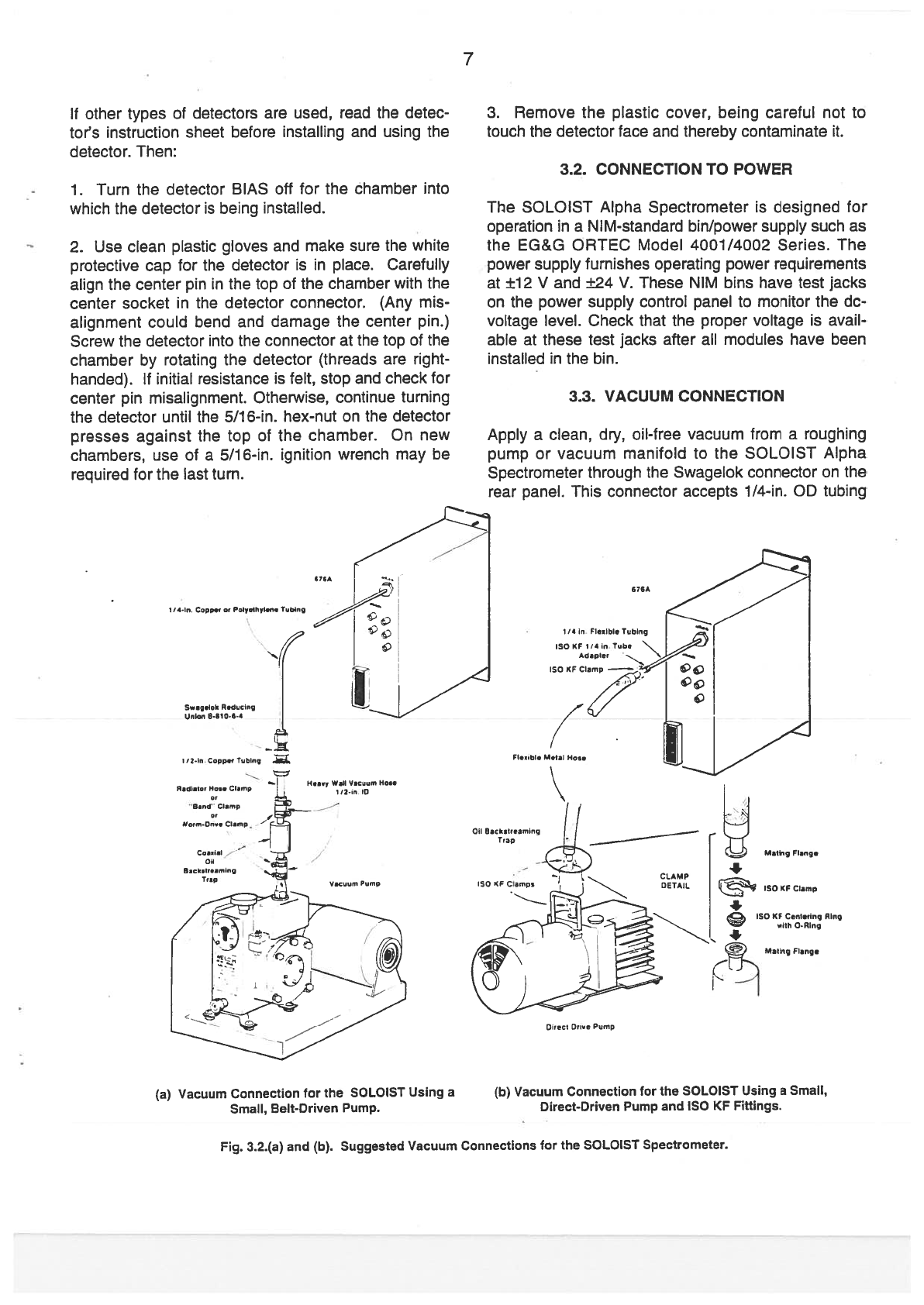
3.3.
VACUUM
CONNECTON
Apply
a
clean,
dry,
oil-free
vacuum
from
a
roughing
pump
or
vacuum
manifold
to
the
SOLOIST
Alpha
Spectrometer
through
the
Swageiok
connector
on
the
rear
panei.
This
connector
accepts
1/4-in. CD
tubing
fb)
Vacuum
Connection
for
the
SOLOIST
Using
a
SmaII,
Direct-Driven
Pump
and
ISO KF
Fittings.
676A
II4.n.
Copp.
o,
PoIyrhy.n.
Toblng
Swg.kR.dflg
SiBA
/2.io
Copper
T.bing
Rodiolo,
50••
CIdn,p
‘Bdnd
C.,,,p
1/4
o
FIebIe
Tbnq
ISO
SF114,,
Tob
Addpte,
-
ISO
SF
CIan,p
4
Hn.y
W.H
VICIam
Halo
l/2.,n.
lO
FIeable
U,,Il
HO,,,
011
SacI
r.amng
Trap
CCAUP
DErAS.
Mali,,5
Flange
Aing
(a)
vacuum
Connection
for
the
SOLOIST
Using
a
SmaII,
Bet-Driven
Pump.
01,001
Drive
Pump
Fig.
3.2.(a)
and
(b).
Suggested
Vacuum
Connections
for
the
SOLOIST
Spectrometer.
8
and
is
accessible
when the
module
has
been
instailed
in
the
NIM
bin
[(Fig.
3.2
(a)
and
(b)J.
For
a
single
SOLOIST Alpha
Spectrometer, the
pump
should
have
a
displacement
of
about
2
CFM
(57
liter/min).
if
sev
eral SOLOIST
Alpha
Spectrometer
modules
are
con
nected
togethet
via
a
manifold,
the
pump
should
have
a
displacement
of
about
4
CFM
(113
liter/min).
For
larger
systems
(more
than
four
modules),
a
pump
with
a
displacement
of
6.7
CFM
(190
titers/min)
should
be
used.
An
operating
pressure
of
<50
millitorr
should be
adequate
for
most
applications.
Set
the
front-panel
PUMP/HOLD/VENT
contrai
at
VENT
to
isolate the
vacuum
source
from
the
chamber
and
to
vent
the chamber
to
atmospheric
pressure.
With
the
chamber
door
closed,
the
contrai
can
be
set
at
PUMP
to
connect
the
chamber
to
the
vacuum
source.
Do
not
set
the
control
at
PUMP
unless
the
door
is
closed,
ar
the
vacuum
source
will
be
connect
ed
directiy
to
atmospheric
pressure
through
the
open
chamber.
The
control
can
be
placed
in
the
HOLD
position
to
solate
the
chamber
from
the
manifoid
without
venting
the sample.
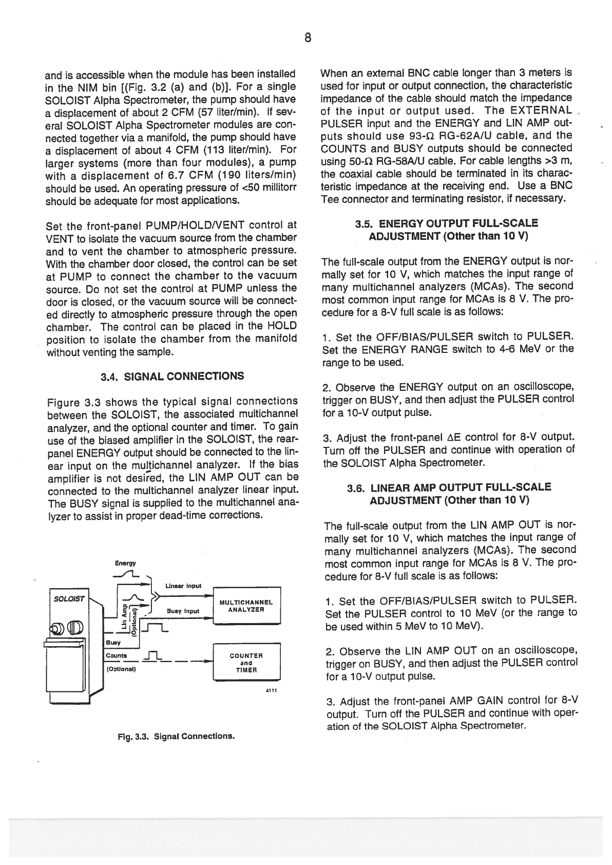
3.4.
SIGNAL
CONNECTIONS
Figure 3.3
shows
the
typical
signal
connections
between
the
SOLOIST,
the
associated
multichannel
analyzer, and
the
optional
counter
and
timer.
lo
gain
use
of
the
biased
amplifler
in
the
SOLOIST,
the
rear
panei
ENERGY
output should
be
connected
to
the
lin
ear
input
on
the
multichannet
anaiyzer.
lf
the bias
amplitier
is
not
desired, the
LIN
AMP
OUT
can
be
connected
to
the
muitichannel
anaiyzer
linear
input.
The
BUSY
signai
is
supplied
to
the
multichannel
ana
Iyzer
to
assist
in
proper
dead-time
corrections.
When
an
external
BNC
cable
longer
than
3
meters
is
used
for input
or
output
connection,
the characteristic
impedance
of
the
cable
shouid
match
the
impedance
of
the
input
or
output
used.
The
EXTERNAL
PULSER
input
and
the
ENERGY
and
LIN
AMP
out
puts should
use
93-2
RG-62A/U
cable,
and
the
COUNTS
and
BUSY
outputs
should
be
connected
using
50-i2
RG-58NU cabie.
For
cabie
lengths
>3
m,
the
coaxial
cable
should
be
terminated
in
its
charac
teristic
impedance
at
the
receiving
end,
Use
a
BNC
Tee
connector
and
terminating
resistor,
if
necessary.
3.5.
ENERGY
OUTPUT FULL-SCALE
ADJUSTMENT
fOther
than
10
V)
The
full-scale
output
from
the
ENERGY
output
is
nor
mally
set
for
10
V,
which
matches
the
input
range
ot
many
multichannel
analyzers
(MCAs).
The
second
most
common
input
range
for MCAs
is
8
V.
lhe
pro
cedure
for
a
8-V
fuli
scale
is
as
foliows:
1.
Set
the
OFF/BIAS/PULSER
switch
to
PULSER.
Set
the
ENERGY
RANGE
switch
to
4-6
MeV
or
the
range
to
be
used.
2.
Observe
the
ENERGY
output
on
an
oscilioscope,
trigger
on
BUSY,
and then
adjust the
PULSER
contrai
for
a
10-V
output pulse.
3.
Adjust
the
front-panel
E
control
for
8-V
output.
Turn
off
the
PULSER
and continue
with
operation
ot
the
SOLOIST Alpha
Spectrometer.
3.6.
LINEAR
AMP
OUTPUT
FULL-SCALE
ADJUSTMENT
(Other
than
10
V)
lhe
full-scale
output
from
the
LIN
AMP
OUT
is
nor
mally
set
for 10
V,
which
matches
the
input
range
of
many
multichannel
anaiyzers
(MCAs).
The
second
most
common
input
range
for
MCAs
is
8
V.
The
pra
cedure
for
8-V
fuil
scale
is
as
foliows:
1.
Set
the
OFF/B1AS/PULSER
switch
to
PULSER.
Set
the
PULSER
contrai
to
10
MeV
for
the
range
to
be
used
within
5
MeV
to
10
MeV).
2.
Observe
the
LIN
AMP
OUT
on
an
oscilioscope,
trigger
on BUSY,
and
then
adjust the
PULSER contrai
for
a
10-V
output
pulse.
3.
Adjust
the
front-panei
AMP
GAIN
contrai
for
8-V
output.
Turn
off
the
PULSER
and continue
with
oper
ation
ot
the
SOLO
IST
Alpha
Spectrometer.
Energy
-1
(Optional)
TER
4111
Fig.
3.3.
Signal
Connections.
9
4.
OPERATION
The
nformation
in
Section
3
includes
ali
of
the
prelim
inary
selections
that
are
to
be
made
for
the
SOLO
IST
Alpha
Spectrometer.
Operation,
then,
consists
of
inserting
a
sample
that
is
to
be
exarnined
into
the
chamber
and
proceeding
with
data
accumulation.
Basic
control
settings
that
should
be
used
before
ínserting
a
sampie
and
between
operating
cycles
are:
OFF/BIAS/PULSER
VACUUM
Control
ENERGY
RANGE
PULSER
Dial
DET
BIAS
ADJ
Then
use
the
following
steps:
1.
Piace the
standard
sampie
in
the chamber.
2.
Evacuate
the
chamber.
lf
this
module
has
a
com
mon
vacuurn
with
other
SOLOIST Alpha
Spec
trometers,
put
the
other modules
on
HOLD
while
this
module
is
pumped
down.
3.
Turn
on
the
BIAS,
and
count
the
standard.
4.
Perform
the energy
and
efficiency
calibration.
5.
Repeat
steps
1-3
with
a
prepared
sample.
Note:.
for
quantitatively
meaningful
results,
the
sample
must
be
placed
at
the
sarne
distance
from
the
detector
as
the
calibration
standard.
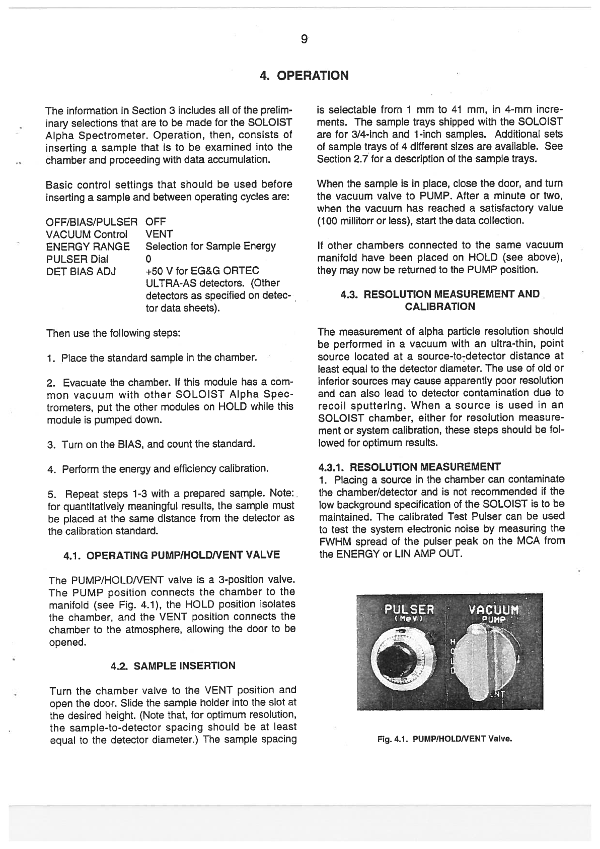
4.1.
OPERATING
PUMP/HOLDNENT
VALVE
lhe
PUMP!HOLDNENI
vaive
is
a
3-position vaive.
The
PUMP
position
connects
the
chamber
to
the
manifold
(see
Fig.
4.1),
the
HOLD
position
isolates
the chamber,
and
the
VENT
position
connects
the
chamber
to
the
atmosphere,
allowing
the
door
to
be
opened.
4.2.
SAMPLE
INSERTION
Turn
the
chamber
valve
to
the
VENT
position
and
open
the
door.
Silde
the
sample
holder
into
the
slot at
the
desired
height.
(Note
that,
for
optimum
resolution,
the
sample-to-detector
spacing
should
be
at
least
equal
to
the
detector
diameter.)
The
sarnple
spacing
is
selectable
from
1
mm
to
41
mm,
in
4-mm
incre
ments.
lhe
sample
trays
shipped
with
the
SOLOIST
are
for
3/4-inch
and
1-inch
sampies.
Additional
sets
of
sample
trays
of
4
different
sizes
are
available.
See
Section
2.7
for
a
description
of
the
sample
trays.
When
the
sample
is
in
place,
dose
the
door,
and
turn
the
vacuum
valve
to
PUMP.
After
a
minute
or
two,
when
the
vacuum
has
reached
asatisfactory
value
(100
millitorr
or
less), start
the
data
coliection.
lf
other
chambers
connected
to
the
sarne
vacuum
manifold
have
been
placed
on
HOLD
(see
above),
they may
now
be
returned
to
the
PUMP position.
4.3.
RESOLUTION MEASUREMENT
AND
CAUBRATION
lhe
measurement
of
alpha
particle
resolution
should
be
performed
in
a
vacuurn
with
an
ultra-thin,
point
sou
rce
located
at
a
sou
rce-to-detector distance
at
least equal
to
the
detector
diameter.
The
use
of
old
or
inferior
sources
may
cause
apparently
poor
resolution
and
can
also
Iead to
detector
contarnination
due
to
recoil
sputtering.
When
a
source
is
used
in
an
SOLOISI
charnber, either
for
resolution
measure
ment or
systern
calibration,
these
steps
should be
foi
lowed
for
optimum
resuits.
4.3.7.
RESOLUTION MEASUREMENT
1.
Piacing
a
source
in
the
chamber
can
contaminate
the
chamber/detector
and
is
not
recommended
if
the
low
background
specification
of
the
SOLOIST
is
to
be
maintained.
lhe
caiibrated
Test
Pulser
can
be
used
to
test
the
system
electronic
noise
by
rneasuring the
FWHM
spread
of
the
pulser
peak
on
the
MCA
from
the
ENERGY or
LIN
AMP
OUT.
0FF
VENT
Selection
for
Sample
Energy
o
+50
V
for
EG&G
ORTEC
ULTRA-AS
detectors.
fOther
detectors
as
specified
on
detec
tor
data
sheets).
Fig.
4.1.
PUMP/HOLDNENT
Valve.
lo
2.
Evacuate
the
chamber.
3.
Turn
the
BIAS
on.
Wait
for 2
minutes.
4.
Accumulate
a
peak
containing
at
least
1
OOO
counts
in
the
peak
channel.
5.
Determination
of
the
resolution
requires
the
meas
urement
of
the
fuU-width
at
1/2
maximum
(FWHM)
of
the
peak.
Note:
lf
the
source
is
to
be
used,
place
the
source
on
a
sample
tray
and
insert
tinto
the
SOLQIST
cham
ber. Placing
the source
as
far
as
possible
from
the
detector
helps reduce
any
solid-angle-related
and/or
count-rate
problems.
4.3.2.
CALIBRATION
System
calibration
is
essentially
composed
of
two
parts:
1.
Counting
a
known
standard
containing
two
alpha
emitters,
and
using
the
known
energies
to
determine
the
energy
calibration.
For
low-background
applica
tions
the
calibrated
Test
Pulser
can
be
used
to
place
a
peak
near each
end
of
the
selected
Energy
Range
then:
E=A+B*Chn
where
A
is
the
energy
of
the
lowest
channel
in
the
system
in
MeV
and
6
is
the
gain
in
MeV/channel.
E
is
the
energy
of
channel
Chn. This
process
is
carried
out
easily
via
the
MCA
Emulation
software
(see
rele
vant
manual).
For
use
with
other
MCA
systems
see
the pertinent manual.
2.
Performing
an
efficiency
calibration.
The
efficiency
calibration
is
a
determination
ot
the
ratio
between the
number
ot
alpha
particles
of
a
particular
nuclide
and
enetgy
emiffed
by
the
source,
and
the
number
actual
ly
recorded
from
that
source
in
the
corresponding
spectral
peak.
Efficiency
calibration
may
be determined
manuafly,
or
may
be
determined
as
a
part
of
a
quantitative
analy
sis
package
such
as
EG&G
ORTEC’s
ALPHAMArM.
Unlike
gamma-ray detectors, the
efficiency
of
a
solid
state
alpha
detector
is
constant
over
the
energy range
of
interest
to
alpha
spectroscopists.

11
5.
THEORY
OF
OPERATION
The
complete
schematics
for
the
SOLOIST
Alpha
Spectrometer
[Part
No.
761250
(Alpha
Spectrometer)
and 764030
(Linear
Amplifier)]
are
included
at
the
back
of
this
manual.
Figure
5.1 is
a
block
diagram
of
the
electronics.
The
detector
voltage
(OFF/BIAS/PULSER)
switch
on
the
front
panei
turns
power
on
and
off
for
the
variable
100-V
power
suppiy.
The
power
is
on
in
both
the
BIAS
and
PULSER
positions.
The
poiarity
is
set
by
jumper
Ji,
which
is
actuaily
three
separate
jumpers
(see
schematics).
The
indica
ted
poiarity
is
positive,
which
is
appropriate
when
an
EG&G
ORTEC
ULIRA-AS
or
standard detector
is
used.
When
the
detector
voltage
is
positive,
its
out
put
pulses
are
negative.
When
they
pass
through
the
inverting
preamplifier
they
are
positive,
and
this
is
the
polarity
that
is
then
selected
by
the
pair
of
jumpers
J3,
on
the
PWB.
if
a
Ruggedized
surface
barrier
detector
is
used,
ali
five
of
ttese
jumpers
must
be
changed
to
“—“
because
the
Ruggedized
detector
operates
on
a
negative
voltage and
generates
positive output
pulses,
which
are
then
inverted
and
are
negative
pulses
at
the
J3
location
in
the
circuit.
The
100-V
power
supply output
on
the
PWB
can
be
tested
for
both
poiarity
and
amplitude
at
test
point
TP1,
which
is
identif
leU
on
the
PWB.
The
variable
O
to
100
V
bias voltage
can
be
measured
at
the
rear-panel
test
jack
labeled
HV.
The
detector leakage
current
can
be
calculated
from
the
voltage
across
the
1.1-Me
resistor,
between rear-panel
test jacks
DET
and
HV.
A
10-M2
impedance
meter
should be
used.
The
out
put
ot
the
BIAS
supply
is
applied
through
a
high
impedance
(totaling
23
M2)
to
the
dc
connection
between
the
detector
and
the
preamplif
ler.
lhe
output
from
the
charge
sensitive
preamplif
ler
can
be
checked
at
TP2.
lhe
nominal
conversion
gain
is
45
mV/MeV,
lhe
preamplitier
gain
from
the
EXTER
NAL
PULSER
input
is
nominally
“—1”
at
lP2.
lhe
front-panel
PULSER
switch
(OFF/BIAS/PULSER)
turns
power
on
and
off
for
the
test
pulser.
lhe
test
pulser
can
be
set
using
the
10-turn,
front-panel
poten
DETECTOR
VOLTAQE
Fig.
5.1.
Detailed
Block
Dagram
of
the
SOLOIST
Alpha
Spectrometer.
12
tiometer
to
furnish
the
equivaient pulse
amplitude
for
0
to
10
MeV
at
the
input
to
the
preamplifier.
A
screw
driver
calibration
is
included
on
the
PWB
for
factory
adjustment
of
the
test
pulser
circuit
and
should
not
be
changed
by
the
customer.
When
the
front-panel
tog
gle
switch
is
set
at
BIAS,
the
test
pulser
is
turned
off
and
does
not
appear
in
the
output
spectrum.
Pulses
from
the
detector and/or
the
test
pulser are
inverted
by
the
preamplifier
and
are
furnished
as
the
input
to
the
amplifier
that inciudes
the
first
integration
and
differentiation
shaping
circuits.
The
amplifier
can
be
calibrated
by
a
factory-adjusted
trim
potentiometer
on
the
PWB,
The
output
is
a
shaped
negative
pulse
that
can
be
observed
at
test
point
1P3.
The
pulse
at
lP3
is
furnished
into
a
fixed-level
dis
criminator
U3
and
through
a
diode
dc-restorer
and
integration
network.
lf
the amplitude
represents
—2.5-MeV
or
more,
the
discriminator
fites
and
gener
ates
a
positive-shaped
pulse that
is
used
to
enable
the
stretcher.
This
pulse
is
also
provided
as
the
COUNTS
output
signal.
lhe
pulse
from
the
second
integration
shaping
circuit
is
futnished
to
the
stretch
er.
lf
the
stretcher
is
enabled,
the
peak
amplitude
is
stretched
to
improve
the
measurement
accuracy
of
the
MCA,
which
uses
the
ENERGY
output
for
meas
urement.
lt
the
sttetcher
is
not
enabled
(because
the
pulse
represents
<2.5
MeV),
the
output
is
passed
to
the
biased
amplifier without
being
stretched.
lhe
out
put
of
the
sttetcher
is
a
negative
pulse
and
can be
monitoted
at
test
point
lP4
on
the
PWB.
lhe
biased
amplifier
accepts
the
stretcher
output
and
the
bias
levei
selected
by
the front-panel
ENERGY
RANGE
switch
(low
end
of
range). The bias
levei,
or
lower
levei,
accepted
into
the
biased
amplifier
can
be
set
at
3,
4,
5,
or
6
MeV by
the
ENERGY
RANGE
switch
and
can
be
adjusted
by
±10%
by
the
ftont
panei
screwdtiver
control,
E
BIAS.
lhe
function
of
the
biased
amplifier
is
to
subtract
the
bias
levei
from
the
input
pulse amplitude
and
to
amplify
the
excess
amplitude
by
a
factor
of
10
on
the
3-5,
4-6,
5-7,
and
6-8
MeV
ranges,
a
factor
of
6.7
on
the
4-7
MeV
range,
or
a
factor
of
4
on
the
3-8
MeV
range.
lhe
out
put
of
the
biased
amplif
ler
is
a
positive
pulse
with
an
amplitude
in
the
range
of
O
to
10
V
that
is
proportionai
to
the
amount
by
which
the
detected
input
energy
exceeds
the
selected
bias
levei,
lhe
full-scale
output
of
10
V
can
be
adjusted
down
to
7.75
V
using
the
front-panei
screwdriver
control,
E.
51.
SOLOIST
ALPHA
SPECTROMETER
LINEAR
AMPUFIER
SCHEMATIC
lhe
pulse
at
lP3
is
also furnished
to
a
positive gain
of 10
ampiifier
with
a
diode-iimited,
continuous
dc
restoration
ioop
(see
Linear
Amplifier
schematic).
lhe
second
integration
for
the
tear-panei
LIN
AMP
QUI
is
implemented
in
the
amplifier
input
network.
lhe
LIN
AMP
OUI
is
a
positive 1-.ts
shaped
pulse.
The
output
amplitude
is
adjustabie
ovet
a5-MeV
to
10-MeV
range
by
the
front-panel
screwdriver
controi,
AMP
GAIN.
lhe
output
is
factory
set
to
10
MeV
at
10V.
The
BUSY
output
pulse
is
generated
by
a
discrimina
tor
that
provides
a
+5
V
levei
whenever
the
LIN
AMP
QUI
exceeds
the
discriminator’s
70-mV
reference
voitage.

13
6.
MAINTENANCE
AND
SERVICE
6.1.
DECONTAMINATION
The
normal
background
count
above
3
MeV
for
each
channel
in
the
SOLOIST
should
be <24
counts
per
day
for
the
300- and
450-mm2
ULTRA-AS
Series
detectors.
lf
an
increase
of
background
is
noted,
this
may
be
caused
by
contamination
of
the
chamber
and/or
the
detector
by
residual
deposits
of
alpha-emit
ting
materiais.
Decontamination
of
the
chamber
and
of
the
detector
fif
ULTRATM
or
Ruggedized)
is
indicat
ed.
Non-Ruggedized
surface
barrier
detectors
cannot
be
subjected
to
cleaning
procedures;
con
sult
the
instruction
manual for
the
detector
to
determine
any
measures
that
may
be
helpfuL
6.1.7.
CHAMBER
DECONTAMINATION
Use the
following
steps
to
decontaminate
a
SQLOIST
chamber.
1.
Ensure that
the
power
and
BIAS
switches
are
turned
off.
Remove the detector
from
the
chamber
by
rotating
t
counterciockwise
(right-hand
threads).
lhe
protective
covet
supplied
with
the
detector
should
be
in
place
prior
to
its
removal
to
prevent
damage
to
the
detector.
Plastic
gioves
shouid
be
used
to
prevent
contamination
of
the
hands
or
chamber.
2.
Pour
the cleaning
agent
into a
clean
beaker.
Methanoi,
or
water
with
a
methanol
rinse,
can
be
used
as
the
cleaning
agent.
3.
Moisten
a
cotton
swab
or
a
coffon-covered
stick
with
the cleaning
agent
and
gently
wipe
the
internal
surfaces
of
the
chamber
to
remove any
contamina
tion.
Avoid
contaminatíng vacuum
or
vacuum
gauge
ports.
Plug
hoies
if
necessary.
4.
When
contamination
from
the
surface
is
visible
on
the
cotton
swab,
discard
and
use
a
clean
one
in
order
to avoid
returning
the contaminant
to
other
areas
ot
the
chamber.
5.
When
the
chamber
is
clean,
blow
dry
with
clean
nitrogen
gas.
6.1.2.
ULTRA-AS
DETECTOR
DECONTAMINATION
The
front
surface
ot
an
ULTRA-AS
detector
can
be
cieaned
with
acotton
swab moistened
with
acetone.
Gently
rub
the
detector
surface
with
the
swab.
Repeat
with
fresh
acetone.
Blow
dry
with
dry
nitrogen
gas.
Before
applying
bias,
leave
the
detector
under
vacuum
for 30
minutes
to
remove
ali
surface
mois
tu
re.
6.7.3.
RUGGEDIZED
DETECTOR
DECONTAMINATION
Use
the
following
steps
to
decontaminate
the
front
(aluminum)
surf
ace
of
a
Ruggedized
detector:
1.
Pour
deionized
water
into
a
clean beaker.
2.
Dip
a
cotton
swab
into
the
water
and
then
carefuliy
blot
on
a
clean
tissue
to
remove
the
excess.
3.
GENTLY
swab the
aluminum
surface
of
the
detec
tor.
DO
NOT
“scrub”
the
detector.
Gently
wiping
the
detector’s
aluminum
surface
with
the damp
swab
a
few
tirnes
shouid
pick
up
most
of
the
removable
con
tamination.
it
cotton-covered
sticks
are
used,
loosen
the
cotton around
the
stick
and
be
careful
not
to
allow
the
end
of
the
stick
to
contact
the
aluminum
surface.
4.
Clean the
detector
housing
and
the
protectíve
cover
ín
the
sarne
way.
5.
Blow
dry
with
clean
nitrogen
gas.
Do
not
use
a
house
air
supply.
6.2.
SOLOIST
CHAMBER
REMO
VAL
AND
REPLACEMENT
These
instructions apply
to
the
removai
of
a
vacuum
chamber
assembiy
from
the
SOLOIST
for
the
pur
pose
of
cieaning
or
replacing
the
chamber.
6.2.1.
CHAMBER
REMO
VAL
1.
TURN
0FF
lHE
SOLOIST POWER.
2.
Turn
the
VACUUM
Valve
Knob to
VENT
and open
the
chamber
door.
3.
Place
the
white
protective
cap
on
the
detector
and
remove
the
detector.
lhe
detector
front
surface
should
not
be
touched.
4.
Use
a3/32-in.
AlIen
wrench
to
unscrew
the
three
socket
head
cap
screws
holding
the
chamber
in
piace. Remove
the
two
top
screws
first
and the
bot
tom
screw
last.
5.
Puil
the
chamber
out
slightly
(about
one
inch).
Put
the
screws
back
in
the
holes
and
dose
the
chamber
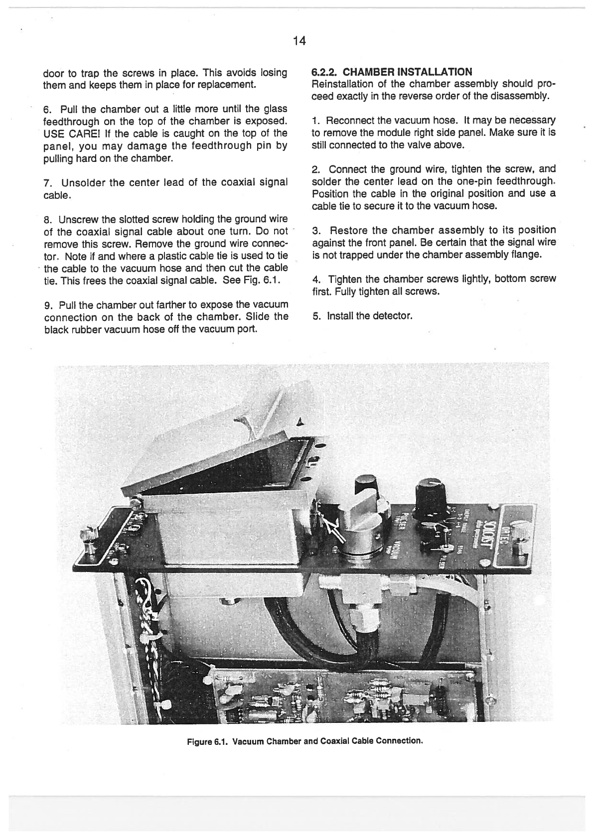
14
door
to
trap
the
screws
in
piace.
This
avoids
tosing
them
and
keeps
them
in
piace
for
replacement.
6.
Puil
the
chamber
out
a
little
more
until
the
glass
feedthrough
on
the
top
of
the
chamber
is
exposed.
USE
CARE!
if
the
cable
is
caught
on
the
top
of
the
panei,
you
may
damage
the
feedthrough
pin
by
puiling
hard
on
the
chamber.
7.
Unsoider
the
center
Iead
of
the
coaxial signal
cabie.
8.
Unscrew
the
slotted
screw
holding
the
ground
wire
of
the
coaxial signai
cable about
one
turn.
Do
not
remove
this
screw. Remove the
ground
wire
connec
tor,
Note
it
and
where
a
piastic
cabie
tie
is
used
to
tie
the
cable
to
the
vacuum
hose
and
then
cut
the
cable
tie.
This
trees
the
coaxial signai
cable.
See
Fig.
6.1.
9.
Puil
the
chamber
out
farther
to
expose
the
vacuum
connection
on
the
back
of
the
chamber.
Slide
the
biack
rubber
vacuum
hose
off
the
vacuum
port.
6.2.2.
CHAMBER
INSTALLATION
Reinstailation
of
the
chamber assembly
should
pro
ceed
exactiy
in
the
reverse
order
ot
the
disassembly.
1.
Reconnect
the
vacuum
hose.
it
may
be
necessary
to
remove
the
module
right
side
panei.
Make
sure
it
is
stiil
connected
to
the
vaive
above.
2.
Connect the
ground
wire,
tighten
the
screw,
and
soider
the
center
iead
on
the
one-pin
feedthrough.
Position
the
cable
in
the
original
position
and
use a
cable
tie
to
secure
it
to
the
vacuum
hose.
3.
Restore
the
chamber
assembly
to
its
position
against
the
front
panei.
Be
certain
that the
signal
wire
is
not
trapped
under
the
chamber
assembly
flange.
4.
Tighten
the
chamber
screws
lightiy,
bottom
screw
first.
Fuliy
tighten
ali
screws.
5.
instali
the
detector.
Figure
6.1.
Vacuum
Chamber
and
Coaxial
Cable
Connectíon.
This manual suits for next models
4
Table of contents
Other EG&G Measuring Instrument manuals


Popular Measuring Instrument manuals by other brands

Wise
Wise F850 Installation & operation manual

Milwaukee
Milwaukee MI455 instruction manual

Kingspan
Kingspan Watchman Radar installation instructions

Audio Precision
Audio Precision B Series Installation Instructions and Specifications

janitza
janitza UMG 503 operating instructions

MRC
MRC INE-PHSJ-5 instruction manual


CARLO GAVAZZI
CARLO GAVAZZI EM24 IS-R2-O2 Series user manual

Magneti Marelli
Magneti Marelli 007950006900 owner's manual

sauermann
sauermann DP500 Installation and operating instructions

Campbell
Campbell 05103 instruction manual

Hugo Müller
Hugo Müller GS 42.0x pro manual

Vigor Equipment
Vigor Equipment V 2795 operating instructions