PR electronics 2223 User manual

Programmable displays with a wide se-
lection of inputs and outputs for display of temperature,
volume and weight, etc. Feature linearisation, scaling,
and difference measurement functions for programming
via PReset software.
Interfaces for analogue and digital
signals as well as HART®signals between sensors / I/P
converters / frequency signals and control systems in Ex
zone 0, 1 & 2 and for some modules in zone 20, 21 & 22.
Galvanic isolators for analogue and digital
signals as well as HART®signals. A wide product range
with both loop-powered and universal isolators featuring
linearisation, inversion, and scaling of output signals.
PC or front programmable modules with
universal options for input, output and supply. This range
offers a number of advanced features such as process
calibration, linearisation and auto-diagnosis.
A wide selection of transmitters for DIN
form B mounting and DIN rail modules with analogue
and digital bus communication ranging from application-
specific to universal transmitters.
Displays
Temperature
Isolation
Ex interfaces
Universal
DK
UK
FR
DE
Side 1
Page 13
Page 25
Seite 37
SIGNALS THE BEST
2223
Dual Switchmode
Power Supply
No. 2223V101-IN (0845)
From ser. no. 970296001

DOBBELT SWITCHMODE
SPÆNDINGSFORSYNING
Type 2223
INDHOLDSFORTEGNELSE
Advarsler . . . . . . . . . . . . . . . . . . . . . . . . . . . . . . . . . . . . . . 2
Sikkerhedsregler . . . . . . . . . . . . . . . . . . . . . . . . . . . . . . . . 3
Overensstemmelseserklæring. . . . . . . . . . . . . . . . . . . . . . 5
Adskillelse af SYSTEM 2200. . . . . . . . . . . . . . . . . . . . . . . 6
Anvendelse . . . . . . . . . . . . . . . . . . . . . . . . . . . . . . . . . . . . 7
Teknisk karakteristik . . . . . . . . . . . . . . . . . . . . . . . . . . . . . 7
Montering . . . . . . . . . . . . . . . . . . . . . . . . . . . . . . . . . . . . . 7
Indgang . . . . . . . . . . . . . . . . . . . . . . . . . . . . . . . . . . . . . . . 7
Udgang . . . . . . . . . . . . . . . . . . . . . . . . . . . . . . . . . . . . . . . 8
Elektriske specifikationer. . . . . . . . . . . . . . . . . . . . . . . . . . 8
Bestillingsskema . . . . . . . . . . . . . . . . . . . . . . . . . . . . . . . . 10
Blokdiagram . . . . . . . . . . . . . . . . . . . . . . . . . . . . . . . . . . . 10
Forbindelsesdiagram. . . . . . . . . . . . . . . . . . . . . . . . . . . . . 11
1

SIKKERHEDSREGLER
DEFINITIONER:
Farlige spændinger er defineret som områderne: 75...1500 Volt DC og
50...1000 Volt AC.
Teknikere er kvalificerede personer, som er uddannet eller oplært til at kunne
udføre installation, betjening eller evt. fejlfinding både teknisk og sikkerheds-
mæssigt forsvarligt.
Operatører er personer, som under normal drift med produktet skal indstille og
betjene produktets trykknapper eller potentiometre, og som er gjort bekendt
med indholdet af denne manual.
MODTAGELSE OG UDPAKNING:
Udpak modulet uden at beskadige dette, og sørg for, at manualen altid følger
modulet og er tilgængelig. Indpakningen bør følge modulet, indtil dette er mon-
teret på blivende plads.
Kontrollér ved modtagelsen, at modultypen svarer til den bestilte.
MILJØFORHOLD:
Undgå direkte sollys, kraftigt støv eller varme, mekaniske rystelser og stød, og
udsæt ikke modulet for regn eller kraftig fugt. Om nødvendigt skal opvarmning,
udover de opgivne grænser for omgivelsestemperatur, forhindres ved hjælp af
ventilation.
Alle moduler hører til Installationskategori II, Forureningsgrad 1 og Isolations-
klasse II.
INSTALLATION:
Modulet må kun tilsluttes af teknikere, som er bekendte med de tekniske
udtryk, advarsler og instruktioner i manualen, og som vil følge disse.
Hvis der er tvivl om modulets rette håndtering, skal der rettes henvendelse til
den lokale forhandler eller alternativt direkte til:
PR electronics A/S, Lerbakken 10, DK-8410 Rønde tlf: +45 86 37 26 77.
Installation og tilslutning af modulet skal følge landets gældende regler for
installation af elektrisk materiel bl. a. med hensyn til ledningstværsnit, for-sikring
og placering.
Beskrivelse af indgang / udgang og forsyningsforbindelser findes på blokdia-
grammet og sideskiltet.
32
GENERELT
FARLIG
SPÆNDING
INSTAL-
LATION
ADVARSEL
Dette modul er beregnet for tilslutning til livsfarlige elektriske
spændinger. Hvis denne advarsel ignoreres, kan det føre til
alvorlig legemsbeskadigelse eller mekanisk ødelæggelse.
For at undgå faren for elektriske stød og brand skal manualens
sikkerhedsregler overholdes, og vejledningerne skal følges.
De elektriske specifikationer må ikke overskrides, og modulet
må kun benyttes som beskrevet i det følgende.
Manualen skal studeres omhyggeligt, før modulet tages i brug.
Kun kvalificeret personale (teknikere) må installere dette modul.
Hvis modulet ikke benyttes som beskrevet i denne manual, så
forringes modulets beskyttelsesforanstaltninger.
ADVARSEL
For at overholde sikkerhedsafstande må moduler med to ind-
byggede relæer ikke tilsluttes både farlig og ikke-farlig spæn-
ding på samme moduls relækontakter.
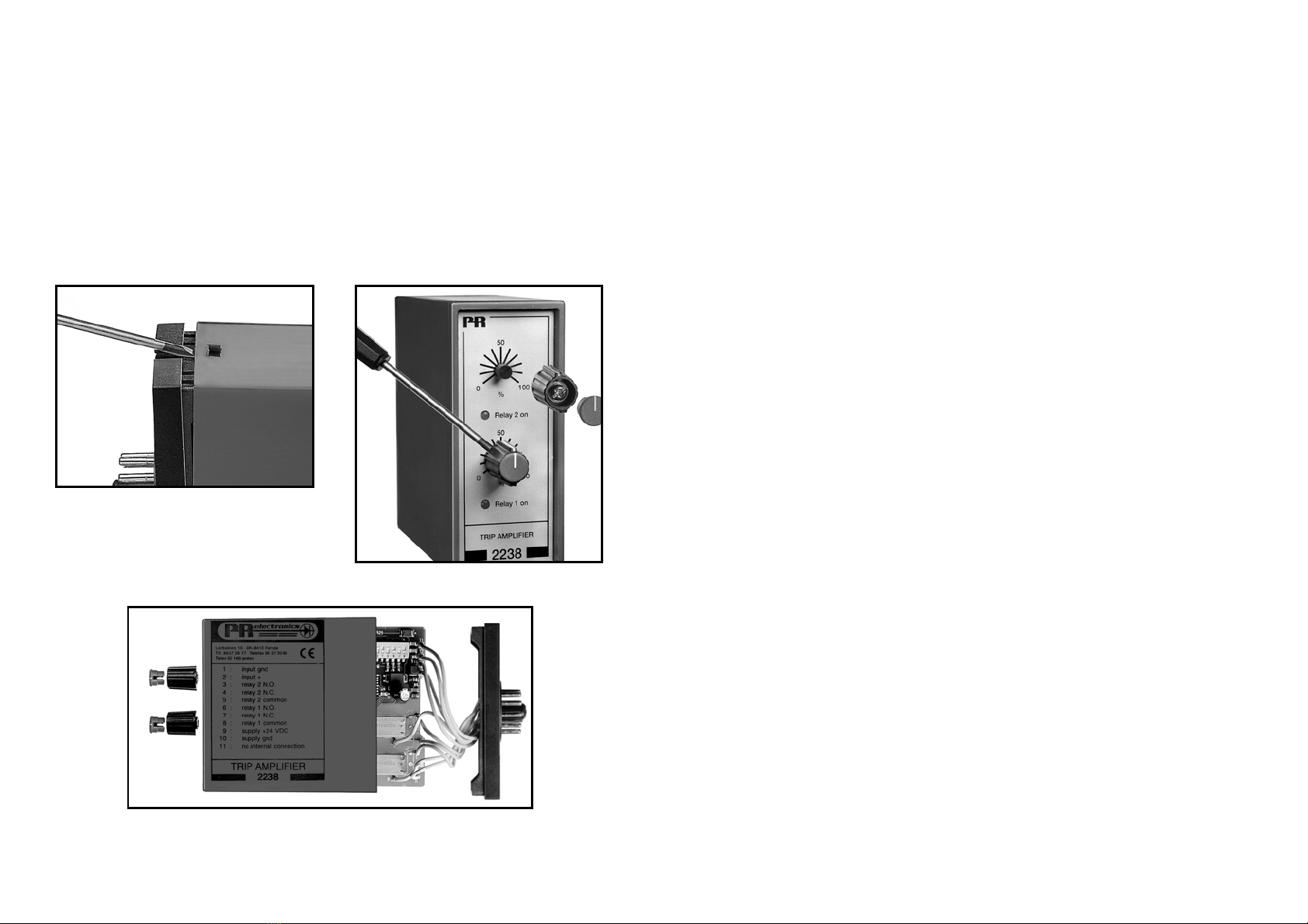
SYSTEM 2200 monteres i sokkel type S3B Releco (bestillings-
nummer 7023).
Trekant med udråbstegn: Advarsel / krav. Hændelser der kan
føre til livstruende situationer.
CE-mærket er det synlige tegn på modulets overensstemmelse
med direktivernes krav.
Dobbelt isolation er symbolet for, at modulet overholder ekstra
krav til isolation.
SIGNATURFORKLARING:
ADVARSEL
Der må ikke tilsluttes farlig spænding til modulet, før dette er
fastmonteret, og følgende operationer på modulet bør kun udfø-
res i spændingsløs tilstand og under ESD-sikre forhold:
Adskillelse af modulet for indstilling af omskiftere og jumpere.
Installation, ledningsmontage og -demontage.
Fejlfinding på modulet.
Reparation af modulet og udskiftning af sikringer må kun
foretages af PR electronics A/S.

OVERENSSTEMMELSESERKLÆRING
Som producent erklærer
PR electronics A/S
Lerbakken 10
DK-8410 Rønde
hermed at følgende produkt:
Type: 2223
Navn: Dobbelt switchmode spændingsforsyning
er i overensstemmelse med følgende direktiver og standarder:
EMC-direktivet 2004/108/EF og senere tilføjelser
EN 61326-1
For specifikation af det acceptable EMC-niveau henvises til modulets elektriske
specifikationer.
Lavspændingsdirektivet 2006/95/EF og senere tilføjelser
EN 61010-1
CE-mærket for overensstemmelse med lavspændingsdirektivet blev tilføjet i
året: 1997
Rønde, 3. november 2008 Peter Rasmussen
Producentens underskrift
5
For moduler, som er permanent tilsluttet farlig spænding gælder:
For-sikringens maksimale størrelse er 10 A og skal sammen med en afbry-
der placeres let tilgængelig og tæt ved modulet. Afbryderen skal mærkes
således, at der ikke er tvivl om, at den afbryder spændingen til modulet.
KALIBRERING OG JUSTERING:
Under kalibrering og justering skal måling og tilslutning af eksterne spændinger
udføres i henhold til denne manual, og teknikeren skal benytte sikkerhedsmæs-
sigt korrekte værktøjer og instrumenter.
BETJENING UNDER NORMAL DRIFT:
Operatører må kun indstille eller betjene modulerne, når disse er fast installeret
på forsvarlig måde i tavler el. lignende, så betjeningen ikke medfører fare for liv
eller materiel. Dvs., at der ikke er berøringsfare, og at modulet er placeret, så
det er let at betjene.
RENGØRING:
Modulet må, i spændingsløs tilstand, rengøres med en klud let fugtet med
destilleret vand.
ANSVAR:
I det omfang, instruktionerne i denne manual ikke nøje er overholdt, vil kunden
ikke kunne rette noget krav, som ellers måtte eksistere i henhold til den indgå-
ede salgsaftale, mod PR electronics A/S.
4

DOBBELT SWITCHMODE
SPÆNDINGSFORSYNING 2223
• Forsyningsspænding: 24 / 115 / 230 VAC
• Isolation 3,75 kVAC
• 2 justerbare udgange 5...24 VDC
• Udgang: ±5...24 VDC, 10...48 VDC
• Kortslutningssikret
• Termisk beskyttet mod overbelastning
ANVENDELSE:
Forsyning af mindre målesystemer, som kræver 2 stabiliserede spændinger.
Det kan være en kombination af positive og negative spændinger eller 2 adskilte
forsyninger efter behov.
TEKNISK KARAKTERISTIK:
2223 er baseret på switchmode teknologi for at opnå justerbar udgang med
minimum effekttab. Isolationtestspænding mellem indgang og udgange er 3,75
kVAC. Enheden er således velegnet i PELV/SELV strømkredse.
Den dobbelt-isolerede sikkerhedstransformator indeholder en bimetalsikring,
som udkobler indgangskredsløbet, hvis den interne temperatur overstiger 100°C.
Sikringen genindkobler automatisk.
MONTERING:
2223 benytter en standard 11-polet sokkel og kan monteres i alle stillinger.
For optimal afkøling af modulet anbefales det at montere enheden i lodret stilling
og at holde en afstand på mindst 10 mm til nabomoduler.
INDGANG:
Standard forsyningsspænding i henhold til specifikationerne. Galvanisk isolation
sikres af den dobbelt-isolerede sikkerhedstransformator.
76
ADSKILLELSE AF SYSTEM 2200
Modulets bagplade frigøres fra huset ved hjælp af en skruetrækker, som vist på
billede 1.
Inden printet kan udtages, kan det ved moduler med knapper være nødvendigt
at fjerne disse, se billede 2.
Derefter kan bagpladen udtrækkes sammen med printet, men vær opmærksom
på printets placering i huset, da det er muligt at isætte dette i flere positioner.
Træk ikke unødigt i ledningerne, men tag fat i printet, se billede 3.
Nu kan switche og jumpere ændres.
Det er vigtigt, at ingen ledninger kommer i klemme, når bagplade og huset
samles.
Billede 1: Adskillelse af bagplade og hus.
Billede 2: Afmontering af knapper.
Billede 3: Udtagelse af print for dipning og flytning af jumpere.

Belastningseffekt, (10%-max. belast.) ....... < 1,5% / A
Strømbegrænsning (kortslutning)............... Typ. 100 mA
Udgangsripple............................................ < 20 mVRMS
GOST R godkendelse:
VNIIM.......................................................... Se hjemmeside
Overholdte myndighedskrav: Standard:
EMC 2004/108/EF...................................... EN 61326-1
LVD 2006/95/EF ......................................... EN 61010-1
PELV/SELV.................................................. IEC 364-4-41 og EN 60742
9
UDGANG:
Udgangene er justerbare fra 2 potentiometre i fronten i området 5...24 VDC.
To grønne lysdioder, Power on 1 og Power on 2, indikerer aktive udgange.
Kortslutningssikringen begrænser strømmen på hver udgang.
De to forsyninger er galvanisk adskilte med testspænding på 500 VAC og kan
serieforbindes eller benyttes som 2 uafhængige forsyninger med eller uden fælles
gnd. Ved at seriekoble de to udgange opnås 10...48 VDC eller ±5...24 VDC.
De to udganges samlede effekt må ikke overskride 7,5 W.
ELEKTRISKE SPECIFIKATIONER:
Specifikationsområde:
-20°C til +60°C
Fælles specifikationer:
Egetforbrug max ........................................ 4 W
Isolation, test / drift .................................... 3,75 kVAC / 250 VAC
Isolation, udgang 1 / 2, test / drift ............. 500 VAC / 50 VAC (75 VDC)
Transformator ............................................. EN 60742
Temperaturkoefficient................................. 0,05%/°C
Virkning af forsyningsspændings-
ændring (±10%) ......................................... < ±30 mV
Transientstabilitet (10%-max. belast.)........ < 250 mV
EMC-immunitetspåvirkning........................ < ± 0,5%
Relativ luftfugtighed ................................... < 95% RH (ikke kond.)
Mål (HxBxD) ............................................... 80,5 x 35,5 x 84,5 mm
Kapslingsklasse.......................................... IP30
Vægt........................................................... 400 g
Indgang:
Forsyningsspænding.................................. 21,6...26,4 VAC
103,5...126,5 VAC
207...253 VAC
Frekvens..................................................... 50...60 Hz
Udgang:
Udgangsspænding..................................... 4,75...25,2 VDC
Udgangseffekt, total................................... Max. 7,5 W
Udgangsstrøm, pr. kanal............................ 0,5 A / 5 VDC (2,5 W)
0,37 A / 12 VDC (4,5 W)
0,30 A / 15 VDC (4,5 W)
0,18 A / 24 VDC (4,3 W)
8

11
FORBINDELSESDIAGRAM:
99
99
88
88
10 10
10 10
11 11
11 11
+ 5...24 VDC + 10...48 VDC
(- 10...48 VDC)
Serieforbindelse
+/- forsyning
Serieforbindelse
+ el. (-) 10 … 48 VDC
2 forskel. pos. forsyninger
med fælles ground
2 forskel. neg. forsyninger
med fælles ground
+ 5...24 VDC
- 5...24 VDC
- 5...24 VDC
+ 5...24 VDC
- 5...24 VDC
GND
GND
(GND)
GND
GND
GND
GND
10
BESTILLINGSSKEMA:
BLOKDIAGRAM:
Type Version
2223 115 VAC : A
230 VAC : B
24 VAC : D
Udgang 1
Speciel (5...24 VDC) : 0
24 VDC : 1
15 VDC : 2
12 VDC : 3
5 VDC : 4
Udgang 2
Speciel (5...24 VDC) : 0
24 VDC : 1
15 VDC : 2
12 VDC : 3
5 VDC : 4

DUAL SWITCHMODE POWER SUPPLY
Type 2223
CONTENTS
Warnings . . . . . . . . . . . . . . . . . . . . . . . . . . . . . . . . . . . . . . 14
Safety instructions. . . . . . . . . . . . . . . . . . . . . . . . . . . . . . . 16
Declaration of Conformity . . . . . . . . . . . . . . . . . . . . . . . . . 18
How to dismantle SYSTEM 2200 . . . . . . . . . . . . . . . . . . . 19
Applications. . . . . . . . . . . . . . . . . . . . . . . . . . . . . . . . . . . . 20
Technical characteristics . . . . . . . . . . . . . . . . . . . . . . . . . . 20
Mounting . . . . . . . . . . . . . . . . . . . . . . . . . . . . . . . . . . . . . . 20
Input . . . . . . . . . . . . . . . . . . . . . . . . . . . . . . . . . . . . . . . . . 20
Output . . . . . . . . . . . . . . . . . . . . . . . . . . . . . . . . . . . . . . . . 21
Electrical specifications. . . . . . . . . . . . . . . . . . . . . . . . . . . 21
Order . . . . . . . . . . . . . . . . . . . . . . . . . . . . . . . . . . . . . . . . . 23
Block diagram . . . . . . . . . . . . . . . . . . . . . . . . . . . . . . . . . . 23
Connection diagram . . . . . . . . . . . . . . . . . . . . . . . . . . . . . 24
1312

SYMBOL IDENTIFICATION
Triangle with an exclamation mark: Warning / demand.
Potentially lethal situations.
The CE mark proves the compliance of the module with the
requirements of the directives.
The double insulation symbol shows that the module is
protected by double or reinforced insulation.
1514
GENERAL
HAZARD-
OUS
VOLTAGE
INSTAL-
LATION
WARNING!
This module is designed for connection to hazardous electric
voltages. Ignoring this warning can result in severe personal
injury or mechanical damage.
To avoid the risk of electric shock and fire, the safety instructions
of this manual must be observed and the guidelines followed.
The electrical specifications must not be exceeded, and the
module must only be applied as described in the following.
Prior to the commissioning of the module, this manual must be
examined carefully.
Only qualified personnel (technicians) should install this module.
If the equipment is used in a manner not specified by the
manufacturer, the protection provided by the equipment may be
impaired.
WARNING!
Until the module is fixed, do not connect hazardous voltages to
the module. The following operations should only be carried out
on a disconnected module and under ESD safe conditions:
Dismantlement of the module for setting of DIP-switches
and jumpers.
General mounting, connection and disconnection of wires
Troubleshooting the module.
Repair of the module and replacement of circuit breakers
must be done by PR electronics A/S only.
WARNING!
To keep the safety distances, modules with two built-in relays
must not be connected to both hazardous and non-hazardous
voltages on the same module’s relay contacts.
SYSTEM 2200 must be mounted in socket type S3B Releco
(order no 7023).

The following apply to fixed hazardous voltages-connected modules:
The max. size of the protective fuse is 10 A and, together with a power
switch, it should be easily accessible and close to the module. The
power switch should be marked with a label telling it will switch off the
voltage to the module.
CALIBRATION AND ADJUSTMENT:
During calibration and adjustment, the measuring and connection of external
voltages must be carried out according to the specifications of this manual.
The technician must use tools and instruments that are safe to use.
NORMAL OPERATION:
Operators are only allowed to adjust and operate modules that are safely fixed
in panels, etc., thus avoiding the danger of personal injury and damage. This
means there is no electrical shock hazard, and the module is easily accessible.
CLEANING:
When disconnected, the module may be cleaned with a cloth moistened with
distilled water.
LIABILITY:
To the extent the instructions in this manual are not strictly observed, the
customer cannot advance a demand against PR electronics A/S that would
otherwise exist according to the concluded sales agreement.
17
SAFETY INSTRUCTIONS
DEFINITIONS:
Hazardous voltages have been defined as the ranges: 75 to 1500 Volt DC, and
50 to 1000 Volt AC.
Technicians are qualified persons educated or trained to mount, operate, and
also troubleshoot technically correct and in accordance with safety regulations.
Operators, being familiar with the contents of this manual, adjust and operate
the knobs or potentiometers during normal operation.
RECEIPT AND UNPACKING:
Unpack the module without damaging it and make sure that the manual always
follows the module and is always available. The packing should always follow
the module until this has been permanently mounted.
Check at the receipt of the module whether the type corresponds to the one
ordered.
ENVIRONMENT:
Avoid direct sunlight, dust, high temperatures, mechanical vibrations and shock,
as well as rain and heavy moisture. If necessary, heating in excess of the stated
limits for ambient temperatures should be avoided by way of ventilation.
All modules fall under Installation Category II, Pollution Degree 1, and Insulation
Class II.
MOUNTING:
Only technicians who are familiar with the technical terms, warnings, and
instructions in the manual and who are able to follow these should connect the
module.
Should there be any doubt as to the correct handling of the module,
please contact your local distributor or, alternatively, PR electronics A/S,
Lerbakken 10, DK-8410 Rønde, Denmark, tel: +45 86 37 26 77.
Mounting and connection of the module should comply with national legislation
for mounting of electric materials, i.a. wire cross section, protective fuse, and
location. Descriptions of Input / Output and supply connections are shown in
the block diagram and side label.
16

HOW TO DISMANTLE SYSTEM 2200
The back panel of the module is detached from the housing by way of a screw-
driver as shown in picture 1.
On a module with knobs, these may have to be removed before the PCB can
be taken out as shown in picture 2.
After this, the back panel can be pulled out together with the PCB, but please
notice the position of the PCB as there is a number of different positions in the
house. Do not pull the wires unnecessarily, instead pull the PCB, see picture 3.
Switches and jumpers can now be moved.
When assembling the back plate and housing, please make sure no wires are
stuck.
19
Picture 1: Dismantlement of back plate
and housing.
Picture 2: Removal of knobs.
Picture 3: Removal of PCBs for adjustment of DIP-switches
and replacement of jumpers.
DECLARATION OF CONFORMITY
As manufacturer
PR electronics A/S
Lerbakken 10
DK-8410 Rønde
hereby declares that the following product:
Type: 2223
Name: Dual switchmode power supply
is in conformity with the following directives and standards:
The EMC directive 2004/108/EC and later amendments
EN 61326-1
For specification of the acceptable EMC performance level, refer to the
electrical specifications for the module.
The Low Voltage directive 2006/95/EC and later amendments
EN 61010-1
The CE mark for compliance with the Low Voltage directive was affixed in the
year: 1997
Rønde, 3 November 2008 Peter Rasmussen
Manufacturer’s signature
18

OUTPUT:
The outputs are adjustable by 2 front potentiometers in the ranges 5...24 VDC.
Two green LEDs, Power on 1 and Power on 2, indicate active outputs.
The short circuit protection limits the current on each output. The two supplies
are galvanically separated with 500 VAC test voltage and can be connected in
series or used as two independent supplies with or without common gnd.
By connecting the two outputs in series, 10...48 VDC or ±5...24 VDC are
achieved. The total output power must not exceed 7.5 W.
ELECTRICAL SPECIFICATIONS:
Specifications range:
-20°C to +60°C
Common specifications:
Internal consumption max ......................... 4 W
Isolation, test / operation ........................... 3.75 kVAC / 250 VAC
Isolation, output 1 / 2, test / operation ...... 500 VAC / 50 VAC (75 VDC)
Transformer ................................................ EN 60742
Temperature coefficient.............................. 0.05%/°C
Effect of supply voltage
change (±10%)........................................... < ±30 mV
Transient stability (10%-max. load)............ < 250 mV
EMC immunity influence ............................ < ±0.5%
Relative air humidity................................... < 95% RH (non-cond.)
Dimensions (HxWxD).................................. 80.5 x 35.5 x 84.5 mm
Protection degree....................................... IP30
Weight ........................................................ 400 g
Input:
Supply voltage ........................................... 21.6...26.4 VAC
103.5...126.5 VAC
207...253 VAC
Frequency................................................... 50...60 Hz
21
DUAL SWITCHMODE POWER SUPPLY 2223
• 24 / 115 / 230 VAC supply voltage
• 3.75 kVAC isolation
• 2 adjustable 5...24 VDC outputs
• Output: ±5...24 VDC, 10...48 VDC
• Short circuit protection
• Thermal protection against overload
APPLICATIONS:
Supply for small measuring systems that demand 2 stabilised voltages.
Either as a combination of positive and negative voltages, or as 2 separate
supplies as required.
TECHNICAL CHARACTERISTICS:
To achieve an adjustable output with minimum power loss, the 2223 is based on
switchmode technology. The isolation test voltage between input and outputs
being 3.75 kVAC, the unit is suitable in PELV/SELV circuits. The double-isolated
safety transformer has a bimetal fuse that disconnects the input circuit if the
internal temperature exceeds 100°C. The fuse resets automatically.
MOUNTING:
The 2223 is for standard 11-pole socket mounting in all positions. To achieve
maximum cooling of the module, mounting in a vertical position at a distance of
minimum 10 mm between neighbouring units is recommended.
INPUT:
Standard supply voltage according to the specifications. The built-in double-
isolated safety transformer ensures galvanic isolation.
20

23
ORDER:
BLOCK DIAGRAM:
Type Version
2223 115 VAC : A
230 VAC : B
24 VAC : D
Output 1
Special (5...24 VDC) : 0
24 VDC : 1
15 VDC : 2
12 VDC : 3
5 VDC : 4
Output 2
Special (5...24 VDC) : 0
24 VDC : 1
15 VDC : 2
12 VDC : 3
5 VDC : 4
Output:
Output voltage............................................ 4.75...25.2 VDC
Output power, total .................................... Max. 7.5 W
Output current, per channel....................... 0.5 A / 5 VDC (2.5 W)
0.37 A / 12 VDC (4.5 W)
0.30 A / 15 VDC (4.5 W)
0.18 A / 24 VDC (4.3 W)
Load effect, (10%-max. load) .................... < 1.5% / A
Current limit (short circuit).......................... Typ. 100 mA
Output ripple .............................................. < 20 mVRMS
GOST R approval:
VNIIM.......................................................... See homepage
Observed authority requirements: Standard:
EMC 2004/108/EC ..................................... EN 61326-1
LVD 2006/95/EC......................................... EN 61010-1
PELV/SELV.................................................. IEC 364-4-41 and EN 60742
22

ALIMENTATION DOUBLE A DECOUPAGE
Type 2223
SOMMAIRE
Avertissements . . . . . . . . . . . . . . . . . . . . . . . . . . . . . . . . . 26
Consignes de sécurité. . . . . . . . . . . . . . . . . . . . . . . . . . . . 28
Déclaration de conformité. . . . . . . . . . . . . . . . . . . . . . . . . 30
Démontage du SYSTEME 2200 . . . . . . . . . . . . . . . . . . . . 31
Applications. . . . . . . . . . . . . . . . . . . . . . . . . . . . . . . . . . . . 32
Caractéristiques techniques . . . . . . . . . . . . . . . . . . . . . . . 32
Montage . . . . . . . . . . . . . . . . . . . . . . . . . . . . . . . . . . . . . . 32
Entrée . . . . . . . . . . . . . . . . . . . . . . . . . . . . . . . . . . . . . . . . 32
Sortie . . . . . . . . . . . . . . . . . . . . . . . . . . . . . . . . . . . . . . . . . 32
Spécifications électriques . . . . . . . . . . . . . . . . . . . . . . . . . 33
Référence de commande . . . . . . . . . . . . . . . . . . . . . . . . . 35
Schéma de principe . . . . . . . . . . . . . . . . . . . . . . . . . . . . . 35
Schéma des raccordements . . . . . . . . . . . . . . . . . . . . . . . 36
2524
CONNECTION DIAGRAM:
99
99
88
88
10 10
10 10
11 11
11 11
+ 5...24 VDC + 10…48 VDC
(- 10...48 VDC)
Serial connection
+/- supply
Serial connection
+ or (-) 10 … 48VDC
2 different pos. supplies
with common ground
2 different neg. supplies
with common ground
+ 5...24 VDC
- 5...24 VDC
- 5…24 VDC
+ 5...24 VDC
- 5...24 VDC
GND
GND
(GND)
GND
GND
GND
GND

SIGNIFICATION DES SYMBOLES
Triangle avec point d’exclamation: Attention ! Si vous ne
respectez pas les instructions, la situation pourrait être fatale.
Le signe CE indique que le module est conforme aux exigences
des directives.
Ce symbole indique que le module est protégé par une isolation
double ou renforcée.
2726
INFORMA-
TIONS
GENERALES
TENSION
DANGE-
REUSE
INSTAL-
LATION
AVERTISSEMENT!
Tant que le module n’est pas fixé, ne le mettez par sous
tensions dangereuses.
Les opérations suivantes doivent être effectuées avec le module
débranché et dans un environnement exempt de décharges
électrostatiques (ESD) : démontage du module pour régler
les commutateurs DIP et les cavaliers, montage général,
raccordement et débranchement de fils et recherche de pannes
sur le module.
Seule PR electronics SARL est autorisée à réparer le module
et à remplacer les disjoncteurs.
AVERTISSEMENT !
Afin de conserver les distances de sécurité, les modules à
deux relais intégrés ne doivent pas être mis sous tensions
dangereuses et non dangereuses sur les mêmes contacts du
relais du module.
Il convient de monter l’appareil SYSTEM 2200 sur un support
du type S3B Releco (numéro de référence 7023).
AVERTISSEMENT!
Ce module est conçu pour supporter une connexion à des
tensions électriques dangereuses. Si vous ne tenez pas
compte de cet avertissement, cela peut causer des dommages
corporels ou des dégâts mécaniques.
Pour éviter les risques d’électrocution et d’incendie, conformez-
vous aux consignes de sécurité et suivez les instructions
mentionnées dans ce guide. Vous devez vous limiter aux
spécifications indiquées et respecter les instructions d’utilisation
de ce module, telles qu’elles sont décrites dans ce guide.
Il est nécessaire de lire ce guide attentivement avant de mettre
ce module en marche. L’installation de ce module est réservée
à un personnel qualifié (techniciens). Si la méthode d’utilisation
de l’équipement diffère de celle décrite par le fabricant, la
protection assurée par l’équipement risque d’être altérée.

Le montage et le raccordement du module doivent être conformes à la
législation nationale en vigueur pour le montage de matériaux électriques, par
exemple, diamètres des fils, fusibles de protection et implantation des modules.
Les connexions des alimentations et des entrées / sorties sont décrites dans le
schéma de principe et sur l’étiquette de la face latérale du module.
Les instructions suivantes s’appliquent aux modules fixes connectés en
tensions dangereuses :
Le fusible de protection doit être de 10 A au maximum. Ce dernier,
ainsi que l’interrupteur général, doivent être facilement accessibles et
à proximité du module. Il est recommandé de placer sur l’interupteur
général une étiquette indiquant que ce dernier mettra le module hors
tension.
ETALONNAGE ET REGLAGE
Lors des opérations d’étalonnage et de réglage, il convient d’effectuer
les mesures et les connexions des tensions externes en respectant les
spécifications mentionnées dans ce guide.
Les techniciens doivent utiliser des outils et des instruments pouvant être
manipulés en toute sécurité.
MANIPULATIONS ORDINAIRES
Les opérateurs sont uniquement autorisés à régler et faire fonctionner des
modules qui sont solidement fixés sur des platines des tableaux, ect., afin
d’écarter les risques de dommages corporels. Autrement dit, il ne doit exister
aucun danger d’électrocution et le module doit être facilement accessible.
MAINTENANCE ET ENTRETIEN
Une fois le module hors tension, prenez un chiffon humecté d’eau distillée pour
le nettoyer.
LIMITATION DE RESPONSABILITE
Dans la mesure où les instructions de ce guide ne sont pas strictement
respectées par le client, ce dernier n’est pas en droit de faire une réclamation
auprès de PR electronics SARL, même si cette dernière figure dans l’accord de
vente conclu.
29
CONSIGNES DE SECURITE
DEFINITIONS
Les gammes de tensions dangereuses sont les suivantes : de 75 à 1500 Vcc
et de 50 à 1000 Vca. Les techniciens sont des personnes qualifiées qui sont
capables de monter et de faire fonctionner un appareil, et d’y rechercher les
pannes, tout en respectant les règles de sécurité. Les opérateurs, connaissant
le contenu de ce guide, règlent et actionnent les boutons ou les potentiomètres
au cours des manipulations ordinaires.
RECEPTION ET DEBALLAGE
Déballez le module sans l’endommager. Le guide doit toujours être disponible
et se trouver à proximité du module. De même, il est recommandé de conserver
l’emballage du module tant que ce dernier n’est pas définitivement monté. A
la réception du module, vérifiez que le type de module reçu correspond à celui
que vous avez commandé.
ENVIRONNEMENT
N’exposez pas votre module aux rayons directs du soleil et choisissez un
endroit à humidité modérée et à l’abri de la poussière, des températures élevées,
des chocs et des vibrations mécaniques et de la pluie. Le cas échéant, des
systèmes de ventilation permettent d’éviter qu’une pièce soit chauffée au-delà
des limites prescrites pour les températures ambiantes.
Tous les modules appartiennent à la catégorie d’installation Il, au degré de
pollution 1 et à la classe d’isolation Il.
MONTAGE
Il est conseillé de réserver le raccordement du module aux techniciens qui
connaissent les termes techniques, les avertissements et les instructions de ce
guide et qui sont capables d’appliquer ces dernières.
Si vous avez un doute quelconque quant à la manipulation du module, veuillez
contacter votre distributeur local. Vous pouvez également vous adresser à PR
electronics SARL, Zac du Chêne, Activillage, 4, allée des Sorbiers, F-69673
Bron Cedex (tél. : (0) 472 140 607) ou à PR electronics A/S, Lerbakken 10, DK-
8410 Rønde, Danemark (tél. : +45 86 37 26 77).
28

DEMONTAGE DU SYSTEME 2200
A l’aide d’un tournevis, dégagez la face arrière du module du boîtier (voir figure
1). Sur un module équipé de boutons, il faut retirer ces derniers pour pouvoir
extraire la carte à circuits imprimés (voir figure 2).
Vous pouvez maintenant extraire la face arrière du module ainsi que la carte
à circuits imprimés. Veuillez repérer la position de cette carte car il existe de
nombreuses positions possibles dans le boîtier. Lorsque vous extrayez la carte
à circuits imprimés, tirez sur celle-ci et évitez de tirer sur les fils (voir figure 3).
Vous pouvez maintenant déplacer les commutateurs et les cavaliers. Lorsque
vous assemblez la face arrière du module et le boîtier, veuillez vérifier que les
fils ne sont pas coincés.
31
Figure 1: Séparation de la face arrière
et du boîtier.
Figure 2: Retrait des boutons.
Figure 3: Extraction de la carte à circuits imprimès pour le
réglage des commutateurs et le remplacement des cavaliers.
DECLARATION DE CONFORMITE
En tant que fabricant
PR electronics A/S
Lerbakken 10
DK-8410 Rønde
déclare que le produit suivant :
Type : 2223
Nom : Alimentation double à découpage
correspond aux directives et normes suivantes :
La directive CEM (EMC) 2004/108/CE et les modifications subséquentes
EN 61326-1
Pour une spécification du niveau de rendement acceptable CEM (EMC)
renvoyer aux spécifications électriques du module.
La directive basse tension 2006/95/CE et les modifications subséquentes
EN 61010-1
La marque CE pour conformité avec la directive basse tension a été apposée
en 1997
Rønde, le 3 novembre 2008 Peter Rasmussen
Signature du fabricant
30

Les 2 alimentations sont isolées galvaniquement avec une tension de 500
Vca et peuvent être connectées en série ou utilisées comme 2 alimentations
indépendantes, avec ou sans terre commune.
En connectant les sorties en série, on obtient soit 10...48 Vcc, soit ±5...±24 Vcc.
La puissance totale des 2 sorties ne doit pas dépasser 7,5 W.
SPECIFICATIONS ELECTRIQUES:
Plage des spécifications:
-20°C à +60°C
Spécifications communes:
Consommation interne max....................... 4 W
Tension d’isolation, test / opération........... 3,75 kVca / 250 Vca
Tension d’isolation, sortie 1 / 2,
test / opération........................................... 500 Vca / 50 Vca (75 Vcc)
Transformateur ........................................... EN 60742
Coefficient de température ........................ 0,05%/°C
Effet d’une variation de la tension
d’alimentation (±10%) ................................ < ±30 mV
Stabilité en régime transitoire
(10% à charge max.) .................................. < 250 mV
CEM (EMC): Effet de l’immunité ............... < ±0,5%
Humidité relative ........................................ < 95%HR (sans cond.)
Dimensions (HxLxP) ................................... 80,5 x 35,5 x 84,5 mm
Degreé de protection ................................. IP30
Poids .......................................................... 400 g
Entrée:
Tension d’alimentation ............................... 21,6...26,4 Vca
103,5...126,5 Vca
207...253 Vca
Fréquence d’alimentation........................... 50...60 Hz
33
ALIMENTATION DOUBLE
A DECOUPAGE 2223
• 2 sorties réglables: de ±5...±24 Vcc, 10...48 Vcc
• Alimentation: 24 / 115 / 230 Vca
• Puissance: max. 7,5 W
• Isolation: 3,75 kVca
• Protection contre les courts-circuits
• Protection thermique contre les surcharges
APPLICATIONS :
Alimentation pour des systèmes de mesure qui demandent 2 tensions stabilisées,
ou une alimentation bipolaire.
CARACTERISTIQUES TECHNIQUES :
Le fonctionnement de l’alimentation est basé sur la technologie du découpage
assurant un rendement optimal. L’entrée et les deux sorties sont isolées
galvaniquement entre elles. Ainsi, le 2223 est apte aux circuits PELV/SELV.
Le transformateur de sécurité à double isolation dispose d’un fusible thermique
qui protège le circuit d’entrée lorsque la température interne dépasse 100°C.
Le fusible se reconnecte automatiquement au-dessous de 100°C.
MONTAGE :
Pour faciliter au mieux le refroidissement par convection naturelle, la
position verticale et un espace de 10 mm entre les modules avoisinants sont
recommandés.
ENTREE :
Alimentations standards 24, 115 ou 230 Vca à spécifier à la commande.
SORTIE :
Les 2 sorties sont réglables à l’aide de 2 potentiomètres en face avant dans la
gamme de 5...24 Vcc. 2 LED vertes (‘Power on 1’ et ‘Power on 2’) indiquent que
les sorties sont actives. Une protection contre les courts-circuits limite le courant
sur chaque sortie à 600 mA.
32

35
REFERENCE DE COMMANDE:
SCHEMA DE PRINCIPE:
Type Version
2223 115 Vca : A
230 Vca : B
24 Vca : D
Sortie 1
Spéciale (5...24 Vcc): 0
24 Vcc : 1
15 Vcc : 2
12 Vcc : 3
5 Vcc : 4
Sortie 2
Spéciale (5...24 Vcc) : 0
24 Vcc : 1
15 Vcc : 2
12 Vcc : 3
5 Vcc : 4
Sortie:
Sortie tension ............................................. 4,75...25,2 Vcc
Puissance de sortie, totale......................... Max. 7,5 W
Puissance de sortie, par voie..................... 0,5 A / 5 Vcc (2,5 W)
0,37 A / 12 Vcc (4,5 W)
0,30 A / 15 Vcc (4,5 W)
0,18 A / 24 Vcc (4,3 W)
Effet de charge (10% à charge max.) ........ < 1,5% / A
Limite de courant (court-circuit)................. Typ. 100 mA
Taux d’ondulation....................................... < 20 mVRMS
Approbation GOST R :
VNIIM.......................................................... Voir site internet
Agréments et homologations: Standard:
EMC 2004/108/CE ..................................... EN 61326-1
DBT 2006/95/CE ........................................ EN 61010-1
PELV/SELV.................................................. IEC 364-4-41 et EN 60742
34

DOPPELTE SCHALTMODUS-
SPANNUNGSVERSORGUNG
TYP 2223
INHALTSVERZEICHNIS
Warnung . . . . . . . . . . . . . . . . . . . . . . . . . . . . . . . . . . . . . . 38
Sicherheitsregeln. . . . . . . . . . . . . . . . . . . . . . . . . . . . . . . . 40
Konformitätserklärung. . . . . . . . . . . . . . . . . . . . . . . . . . . . 42
Zerlegung des SYSTEMs 2200 . . . . . . . . . . . . . . . . . . . . . 43
Anwendung . . . . . . . . . . . . . . . . . . . . . . . . . . . . . . . . . . . . 44
Technische Merkmale . . . . . . . . . . . . . . . . . . . . . . . . . . . . 44
Einbau . . . . . . . . . . . . . . . . . . . . . . . . . . . . . . . . . . . . . . . . 44
Eingang . . . . . . . . . . . . . . . . . . . . . . . . . . . . . . . . . . . . . . . 44
Ausgang . . . . . . . . . . . . . . . . . . . . . . . . . . . . . . . . . . . . . . 45
Elektrische Daten . . . . . . . . . . . . . . . . . . . . . . . . . . . . . . . 45
Bestellangaben . . . . . . . . . . . . . . . . . . . . . . . . . . . . . . . . . 47
Blockdiagramm . . . . . . . . . . . . . . . . . . . . . . . . . . . . . . . . . 47
Schaltplan . . . . . . . . . . . . . . . . . . . . . . . . . . . . . . . . . . . . . 48
3736
SCHEMA DES RACCORDEMENTS:
99
99
88
88
10 10
10 10
11 11
11 11
+ 5...24 Vcc + 10...48 Vcc
(- 10...48 Vcc)
Connexion en série
2 alim. bipolaires
Connexion en série
Alim. -10...-48 Vcc ou
+10...48 Vcc
2 alim. positives
avec terres communes
2 alim. négatives
avec terres communes
+ 5...24 Vcc
- 5...24 Vcc
- 5...24 Vcc
+ 5...24 Vcc
- 5...24 Vcc
GND
GND
(GND)
GND
GND
GND
GND
Other manuals for 2223
1
Table of contents
Languages:
Other PR electronics Power Supply manuals

PR electronics
PR electronics 5420B User manual

PR electronics
PR electronics 5420B User manual

PR electronics
PR electronics 2223 User manual

PR electronics
PR electronics 9420 User manual

PR electronics
PR electronics 2222 User manual

PR electronics
PR electronics 5420B User manual

PR electronics
PR electronics 2220 User manual

PR electronics
PR electronics 2222 User manual

PR electronics
PR electronics 2222 User manual

PR electronics
PR electronics 2220 User manual