PR electronics 5420B User manual

Programmable displays with a wide se-
lection of inputs and outputs for display of temperature,
volume and weight, etc. Feature linearisation, scaling,
and difference measurement functions for programming
via PReset software.
Interfaces for analogue and digital
signals as well as HART® signals between sensors / I/P
converters / frequency signals and control systems in Ex
zone 0, 1 & 2 and for some modules in zone 20, 21 & 22.
Galvanic isolators for analogue and digital
signals as well as HART® signals. A wide product range
with both loop-powered and universal isolators featuring
linearisation, inversion, and scaling of output signals.
PC or front programmable modules with
universal options for input, output and supply. This range
offers a number of advanced features such as process
calibration, linearisation and auto-diagnosis.
A wide selection of transmitters for DIN
form B mounting and DIN rail modules with analogue
and digital bus communication ranging from application-
specific to universal transmitters.
Displays
Temperature
Isolation
Ex interfaces
Universal
DK
UK
FR
DE
Side 1
Page 13
Page 25
Seite 37
SIGNALS THE BEST
5420B
Ex Power Supply
No. 5420BV102-IN (1007)
From ser. no. 030145001
MTS
Messtechnik
Schaffhausen GmbH
CH
-
8260 Stein am Rhein
Telefon +41 52
-
6725000
Messen Prüfen Automatisieren www.mts.ch

1
Ex SPÆNDINGSFORSYNING
PRepower 5420B
Indholdsfortegnelse
Advarsler ............................................................................ 2
Sikkerhedsregler ................................................................. 3
EF-overensstemmelserklæring ........................................... 5
Adskillelse af SYSTEM 5000 .............................................. 6
Anvendelse ......................................................................... 7
Teknisk karakteristik ........................................................... 7
Montage / installation ......................................................... 7
Applikationer ...................................................................... 8
Bestillingsskema ................................................................. 9
Elektriske specifikationer.................................................... 9
Tilslutninger ........................................................................ 11
Blokdiagram ....................................................................... 12
23
Signaturforklaring:
Trekant med udråbstegn: Advarsel / krav. Hændelser der kan føre til
livstruende situationer.
CE-mærket er det synlige tegn på modulets overensstemmelse med EU
direktivernes krav.
Dobbelt isolation er symbolet for, at modulet overholder ekstra krav til
isolation.
Ex - Modulet er godkendt efter ATEX direktivet til brug i forbindelse med
installationer i eksplosionsfarlige områder.
SIKKERHEDSREGLER
DEFINITIONER:
Farlige spændinger er defineret som områderne: 75...1500 Volt DC og
50...1000 Volt AC.
Teknikere er kvalificerede personer, som er uddannet eller oplært til at kunne
udføre installation, betjening eller evt. fejlfinding både teknisk og sikkerheds-
mæssigt forsvarligt.
Operatører er personer, som under normal drift med produktet, skal indstille
og betjene produktets trykknapper eller potentiometre, og som er gjort bekendt
med indholdet af denne manual.
MODTAGELSE OG UDPAKNING:
Udpak modulet uden at beskadige dette, og sørg for, at manualen altid følger
modulet og er tilgængelig. Indpakningen bør følge modulet, indtil dette er mon-
teret på blivende plads.
Kontrollér ved modtagelsen, at modultypen svarer til den bestilte.
MILJØFORHOLD:
Undgå direkte sollys, kraftigt støv eller varme, mekaniske rystelser og stød, og
udsæt ikke modulet for regn eller kraftig fugt. Om nødvendigt skal opvarmning,
udover de opgivne grænser for omgivelsestemperatur, forhindres ved hjælp af
ventilation.
Alle moduler hører til Installationskategori II, Forureningsgrad 1 og Isolations-
klasse II.
ADVARSEL
Dette modul er beregnet for tilslutning til livsfarlige elektriske
spændinger. Hvis denne advarsel ignoreres, kan det føre til
alvorlig legemsbeskadigelse eller mekanisk ødelæggelse.
For at undgå faren for elektriske stød og brand, skal manualens
sikkerhedsregler overholdes, og vejledningerne skal følges.
Specifikationerne må ikke overskrides, og modulet må kun
benyttes som beskrevet i det følgende.
Manualen skal studeres omhyggeligt, før modulet tages i brug.
Kun kvalificeret personale (teknikere) må installere dette modul.
Hvis modulet ikke benyttes som beskrevet i denne manual, så
forringes modulets beskyttelsesforanstaltninger.
ADVARSEL
Der må ikke tilsluttes farlig spænding til modulet, før dette er
fastmonteret og følgende operationer bør kun udføres på modu-
let i spændingsløs tilstand og under ESD-sikre forhold:
Adskillelse af modulet for indstilling af omskiftere og jumpere.
Installation, ledningsmontage og -demontage.
Fejlfinding på modulet.
Reparation af modulet og udskiftning af sikringer må kun
foretages af PR electronics A/S.
ADVARSEL
SYSTEM 5000 skal monteres på DIN skinne efter DIN 46277.
Kommunikationsstikket i SYSTEM 5000 har forbindelse til ind-
gangsklemmer, hvor der kan forekomme farlige spændinger, og
det må kun tilsluttes programmeringsenheden Loop Link via det
medfølgende kabel.
GENERELT
INSTAL-
LATION
FARLIG
SPÆNDING

45
EF-OVERENSSTEMMELSESERKLÆRING
Som producent erklærer
PR electronics A/S
Lerbakken 10
DK-8410 Rønde
hermed at følgende produkt:
Type: 5420B
Navn: Ex Spændingsforsyning
er i overensstemmelse med følgende direktiver og standarder:
EMC-direktivet 2004/108/EF og senere tilføjelser
EN 61326-1
For specifikation af det acceptable EMC-niveau henvises til modulets
elektriske specifikationer.
Lavspændingsdirektivet 2006/95/EF og senere tilføjelser
EN 61010-1
ATEX-direktivet 94/9/EF og senere tilføjelser
EN 50014, EN 50020 og EN 50281-1-1
ATEX-certifikat: DEMKO 99ATEX126256
Bemyndiget organ:
UL International Demko A/S
Lyskær 8
P.O. Box 514
2730 Herlev
Danmark
Rønde, 17. februar 2010 Kim Rasmussen
Producentens underskrift
INSTALLATION:
Modulet må kun tilsluttes af teknikere, som er bekendte med de tekniske
udtryk, advarsler og instruktioner i manualen, og som vil følge disse.
Hvis der er tvivl om modulets rette håndtering, skal der rettes henvendelse til
den lokale forhandler eller alternativt direkte til:
PR electronics A/S, Lerbakken 10,
8410 Rønde, Danmark tlf: +45 86 37 26 77.
Installation og tilslutning af modulet skal følge landets gældende regler for
installation af elektrisk materiel bl.a. med hensyn til ledningstværsnit, for-sikring
og placering.
Beskrivelse af indgang/udgang og forsyningsforbindelser findes på blokdia-
grammet og sideskiltet.
For moduler, som er permanent tilsluttet farlig spænding gælder:
For-sikringens maximale størrelse er 10 A og skal sammen med en
afbryder placeres let tilgængelig og tæt ved modulet. Afbryderen skal
mærkes således, at der ikke er tvivl om, at den afbryder spændingen
til modulet.
Produktionsår fremgår af de to første cifre i serienummeret.
KALIBRERING OG JUSTERING:
Under kalibrering og justering skal måling og tilslutning af eksterne spændinger
udføres i henhold til denne manual, og teknikeren skal benytte sikkerhedsmæs-
sigt korrekte værktøjer og instrumenter.
BETJENING UNDER NORMAL DRIFT:
Operatører må kun indstille eller betjene modulerne, når disse er fast installeret
på forsvarlig måde i tavler el. lignende, så betjeningen ikke medfører fare for liv
eller materiel. Dvs., at der ikke er berøringsfare, og at modulet er placeret, så
det er let at betjene.
RENGØRING:
Modulet må, i spændingsløs tilstand, rengøres med en klud let fugtet med
destilleret vand.
ANSVAR:
I det omfang, instruktionerne i denne manual ikke er nøje overholdt, vil kunden
ikke kunne rette noget krav, som ellers måtte eksistere i henhold til den indgå-
ede salgsaftale, mod PR electronics A/S.
67
Ex SPÆNDINGSFORSYNING
PRepower 5420B
• 2-kanaler
• 5-port 3,75 kVAC galvanisk isolation
• Udgangsspænding > 18 V til Ex-område
• Detektering af aktiv strømsløjfe
• Universel forsyning med AC eller DC
Anvendelse:
• Spændingsforsyning med sikkerhedsbarriere til forsyning af udstyr placeret i
eksplosionsfarligt område.
• Spændingsforsyning med failsafe detektering af aktiv strømsløjfe fra 2-tråd-
stransmittere placeret i eksplosionsfarligt område.
Teknisk karakteristik:
• PR5420B har relæ med skiftekontakter til rådighed på den sikre side. Når
loopstrømmen er indenfor den fastsatte grænse, er relæet trukket.
• Forsyning og udgange er indbyrdes galvanisk adskilte og ikke stelbundne.
Montage / installation:
• Monteres på DIN-skinne, vertikalt eller horisontalt. Der kan installeres 84
kanaler pr. meter.
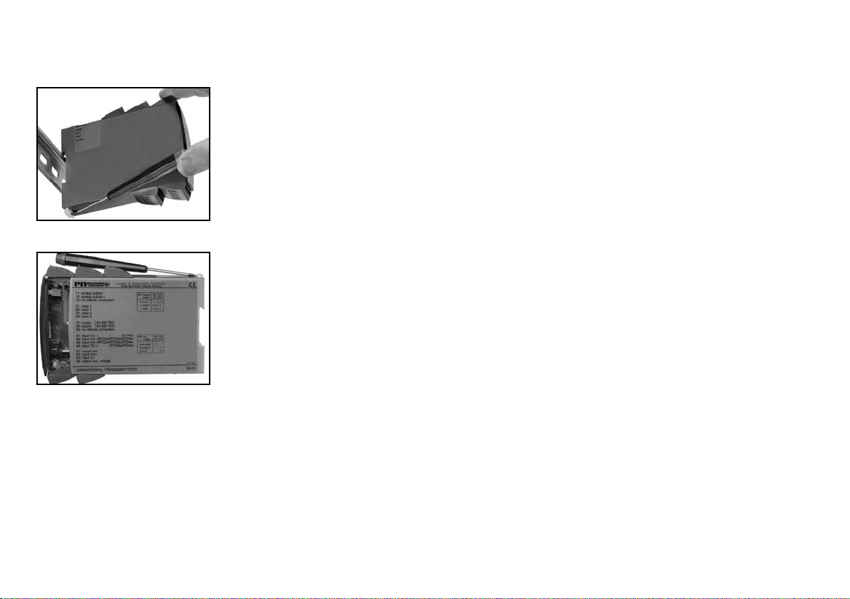
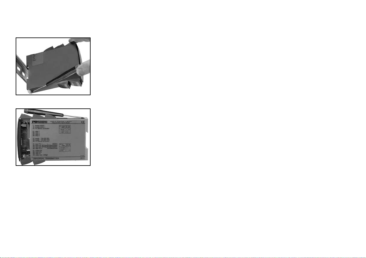
ADSKILLELSE AF SYSTEM 5000
Husk først at demontere tilslutningsklemmerne med farlig spænding.
Billede 1:
Modulet frigøres fra DIN-skinnen ved
at løfte i den nederste lås.
Billede 2:
Printet udtages ved at løfte i den
øverste lås og samtidig trække ud i
frontpladen.
Nu kan switche og jumpere ændres.
89
Elektriske specifikationer:
Specifikationsområde:
-20°C til +60°C
Fælles specifikationer:
Sikring ......................................................... 400 mA T / 250 VAC
Isolationsspænding, test/drift ...................... 3,75 kVAC / 250 VAC
Kalibreringstemperatur ................................ 20...28°C
Ledningskvadrat (max.) ............................... 1 x 2,5 mm2 flerkoret ledning
Klemskruetilspændingsmoment .................. 0,5 Nm
Relativ luftfugtighed .................................... < 95% RH (ikke kond.)
Mål (HxBxD) ................................................ 109 x 23,5 x 130 mm
DIN-skinne type ........................................... DIN 46277
Kapslingsklasse ........................................... IP20
Vægt ............................................................ 215 g
5420B Dobbelt : 2
Type Kanal
Bestillingsskema: 5420B
EMC-Immunitetspåvirkning ................................. < ±0,5%
Udvidet EMC-immunitet:
NAMUR NE 21, A kriterium, gniststøj ................. < ±1%
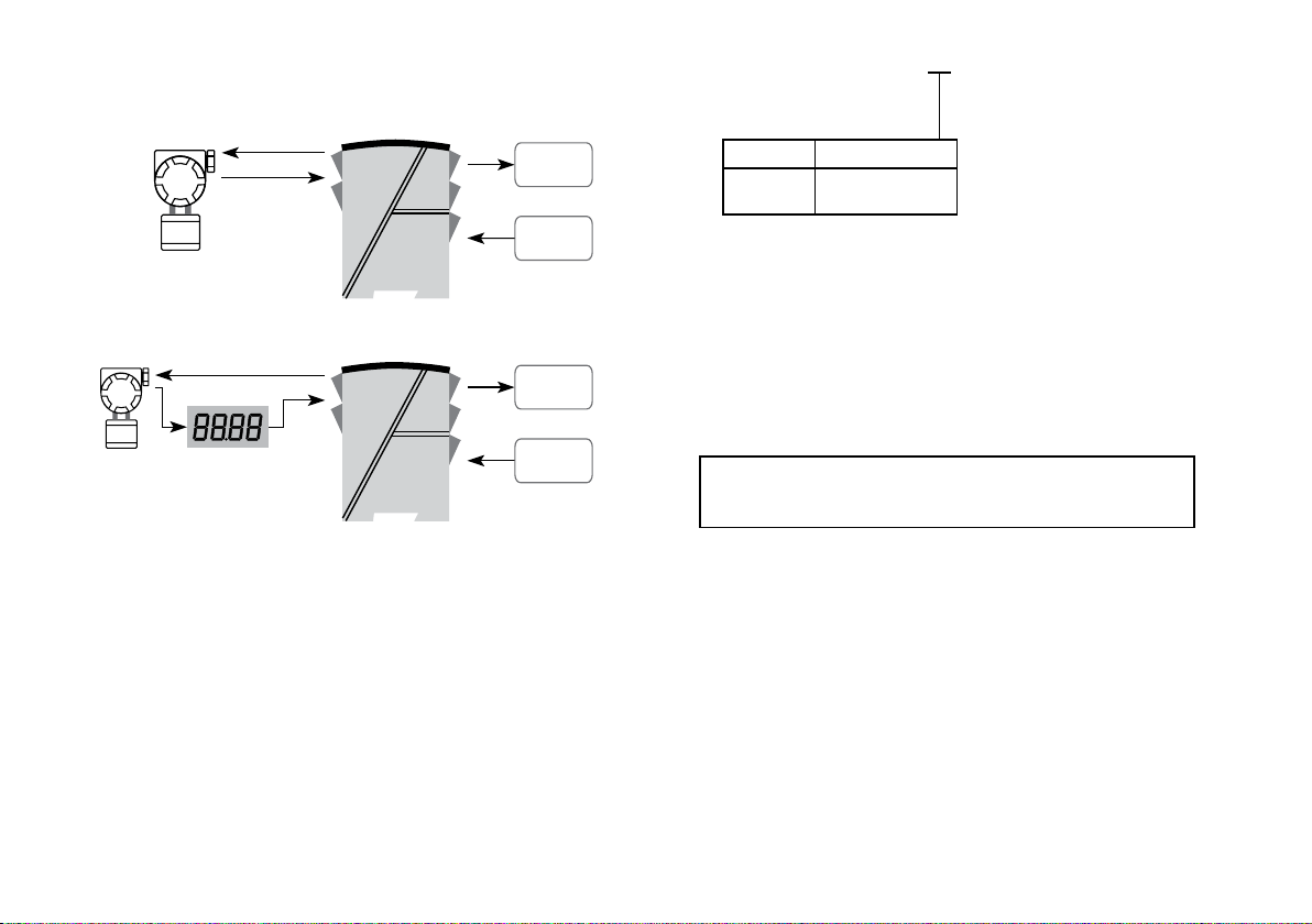
2-Trådstransmitter
2-Trådstransmitter
Loop
alarm
Loop
alarm
Forsy-
ning
Forsy-
ning
10 11
Indgang:
Forsyningsspænding universel .................... 21,6...253 VAC
50...60 Hz
19,2...300 VDC
Egetforbrug ................................................ ≤ 2 W (2 kanaler)
Max. forbrug ................................................ ≤ 4 W (2 kanaler)
Udgange:
Udgangsspænding ...................................... > 18 VDC ved 20 mA
Udgangsstrøm, pr. kanal (Max.) .................. 28 mA
Relæudgange:
Trukket indenfor grænse ............................. > 3,8...< 20,5 mA
V-max .......................................................... 250 VRMS
I-max ........................................................... 2 ARMS
Max. AC effekt ........................................... 100 VA
Max. belastning ved 24 VDC ...................... 1 A
EEx- / I.S.-godkendelse:
DEMKO 99ATEX126256 .............................. II (1) GD
[EEx ia] IIC
Anvendes for zone ...................................... 0, 1, 2, 20, 21 eller 22
Ex- / I.S.-data:
Um ............................................................... : 250 V
Uo ................................................................ : 28 VDC
Io. ................................................................. : 93 mADC
Po ................................................................ : 0,65 W
Lo ................................................................. : 3 mH
Co ................................................................ : 0,08 µF
GOST R godkendelse:
VNIIM & VNIIFTRI, Cert. no. ........................ Se www.prelectronics.dk
Overholdte myndighedskrav: Standard:
EMC 2004/108/EF ....................................... EN 61326-1
LVD 2006/95/EF .......................................... EN 61010-1
PELV/SELV ................................................... IEC 364-4-41 og EN 60742
ATEX 94/9/EF .............................................. EN 50014, EN 50020 og
EN 50281-1-1

12 13
Ex POWER SUPPLY
PRepower 5420B
Table of contents
Warnings ............................................................................ 14
Safety instructions .............................................................. 15
EC Declaration of Conformity ............................................ 17
How to demount SYSTEM 5000 ........................................ 18
Application ......................................................................... 19
Technical characteristics .................................................... 19
Mounting / installation ........................................................ 19
Applications ........................................................................ 20
Order .................................................................................. 21
Electrical specifications ...................................................... 21
Connections ....................................................................... 23
Block diagram .................................................................... 24

14 15
SYMBOL IDENTIFICATION
Triangle with an exclamation mark: Warning/demand. Potentially lethal
situations.
The CE mark proves the compliance of the module with the essential
requirements of the directives.
The double insulation symbol shows that the module is protected by
double or reinforced insulation.
Ex modules have been approved acc. to the ATEX directive for use in
connection with installations in explosive areas.
SAFETY INSTRUCTIONS
DEFINITIONS:
Hazardous voltages have been defined as the ranges: 75 to 1500 Volt DC, and
50 to 1000 Volt AC.
Technicians are qualified persons educated or trained to mount, operate, and
also trouble-shoot technically correct and in accordance with safety regulations.
Operators, being familiar with the contents of this manual, adjust and operate
the knobs or potentiometers during normal operation.
RECEIPT AND UNPACKING:
Unpack the module without damaging it and make sure that the manual always
follows the module and is always available. The packing should always follow
the module until this has been permanently mounted.
Check at the receipt of the module whether the type corresponds to the one
ordered.
ENVIRONMENT:
Avoid direct sun light, dust, high temperatures, mechanical vibrations and
shock, and rain and heavy moisture. If necessary, heating in excess of the
stated limits for ambient temperatures should be avoided by way of ventilation.
All modules fall under Installation Category II, Pollution Degree 1, and Insulation
Class II.
WARNING!
This module is designed for connection to hazardous electric
voltages.
Ignoring this warning can result in severe personal injury or
mechanical damage.
To avoid the risk of electric shock and fire, the safety instructions
of this manual must be observed and the guidelines followed.
The specifications must not be exceeded, and the module must
only be applied as described in the following.
Prior to the commissioning of the module, this manual must be
examined carefully.
Only qualified personnel (technicians) should install this module.
If the equipment is used in a manner not specified by the
manufacturer, the protection provided by the equipment may be
impaired.
WARNING!
Until the module is fixed, do not connect hazardous voltages to
the module.
The following operations should only be carried out on a
disconnected module and under ESD-safe conditions:
Dismantlement of the module for setting of DIP-switches
and jumpers.
General mounting, wire connection and disconnection.
Troubleshooting the module.
Repair of the module and replacement of circuit breakers
must be done by PR electronics A/S only.
WARNING!
SYSTEM 5000 must be mounted on DIN rail according to DIN
46277.
The communication connector of SYSTEM 5000 is connected
to the input terminals on which dangerous voltages can occur,
and it must only be connected to the programming unit Loop
Link by way of the enclosed cable.
HAZARD-
OUS
VOLTAGE
INSTAL-
LATION
GENERAL

16 17
EC DECLARATION OF CONFORMITY
As manufacturer
PR electronics A/S
Lerbakken 10
DK-8410 Rønde
hereby declares that the following product:
Type: 5420B
Name: Ex power supply
is in conformity with the following directives and standards:
The EMC Directive 2004/108/EC and later amendments
EN 61326-1
For specification of the acceptable EMC performance level, refer to the
electrical specifications for the module.
The Low Voltage Directive 2006/95/EC and later amendments
EN 61010-1
The ATEX Directive 94/9/EC and later amendments
EN 50014, EN 50020 and EN 50281-1-1
ATEX certificate: DEMKO 99ATEX126256
Notified body:
UL International Demko A/S
Lyskaer 8
P.O. Box 514
2730 Herlev
Denmark
Rønde, 17 February 2010 Kim Rasmussen
Manufacturer’s signature
MOUNTING:
Only technicians, who are familiar with the technical terms, warnings, and
instructions in the manual and who are able to follow these, should connect the
module. Should there be any doubt as to the correct handling of the module,
please contact your local distributor or, alternatively,
PR electronics A/S, Lerbakken 10, DK-8410 Rønde, Denmark,
tel: +45 86 37 26 77.
Mounting and connection of the module should comply with national legislation
for mounting of electric materials, i.e. wire cross section, protective fuse, and
location. Descriptions of input/output and supply connections are shown in the
block diagram and side label.
The following apply to fixed hazardous voltages-connected modules:
The max. size of the protective fuse is 10 A and, together with a power
switch, it should be easily accessible and close to the module. The
power switch should be marked with a label telling it will switch off the
voltage to the module.
Production year can be taken from the first 2 digits of the serial number.
CALIBRATION AND ADJUSTMENT:
During calibration and adjustment, the measuring and connection of external
voltages must be carried out according to the specifications of this manual. The
technician must use tools and instruments that are safe to use.
NORMAL OPERATION:
Operators are only allowed to adjust and operate modules that are safely fixed
in panels, etc., thus avoiding the danger of personal injury and damage. This
means there is no electrical shock hazard, and the module is easily accessible.
CLEANING:
When disconnected, the module may be cleaned with a cloth moistened with
distilled water.
LIABILITY:
To the extent the instructions in this manual are not strictly observed, the
custom er cannot advance a demand against PR electronics A/S that would
otherwise exist according to the concluded sales agreement.
18 19
Ex POWER SUPPLY
PRepower 5420B
• 2 channels
• 5-port 3.75 kVAC galvanic isolation
• Output voltage > 18 V to Ex area
• Active current loop detection
• Universal supply by AC or DC
Application:
• Voltage supply with safety barrier for the supply of equipment mounted in
hazardous area.
• Voltage supply with failsafe detection of active current loop from 2-wire
transmitters mounted in hazardous area.
Technical characteristics:
• PR5420B has a relay with change-over contacts available in the safe area.
When the loop current is within the defined limit, the relay is ON.
• Supply and outputs are floating and galvanically separated.
Mounting / installation:
• Mounted vertically or horizontally on a DIN-rail. Up to 84 channels per metre
can be mounted.
HOW TO DEMOUNT SYSTEM 5000
First, remember to demount the connectors with hazardous voltages.
Picture 1:
By lifting the bottom lock, the module
is detached from the DIN rail.
Picture 2:
Then, by lifting the upper lock and
pulling the front plate simultaneously
the PCB is removed.
Switches and jumpers can now be
adjusted.

20 21
Electrical specifications:
Specification range:
-20°C to +60°C
Common specifications:
Fuse ............................................................. 400 mA SB / 250 VAC
Isolation voltage, test/operation .................. 3.75 kVAC / 250 VAC
Calibration temperature............................... 20...28°C
Max. wire size .............................................. 1 x 2.5 mm2 stranded wire
Screw terminal torsion ................................ 0.5 Nm
Relative humidity ......................................... < 95% RH (non-cond.)
Dimensions (HxWxD) ................................... 109 x 23.5 x 130 mm
DIN-rail type ................................................ DIN 46277
Protection degree ........................................ IP20
Weight ......................................................... 215 g
Order : 5420B
5420B Double : 2
Type Channel
EMC - immunity influence ................................... < ±0.5%
Extended EMC immunity:
NAMUR NE 21, A criterion, burst ....................... < ±1%
2-wire transmitter
2-wire transmitter
Loop
alarm
Loop
alarm
Supply
Supply

22 23
31 32 33
53
51 52
23
21 22
11 12 13
43
41 42
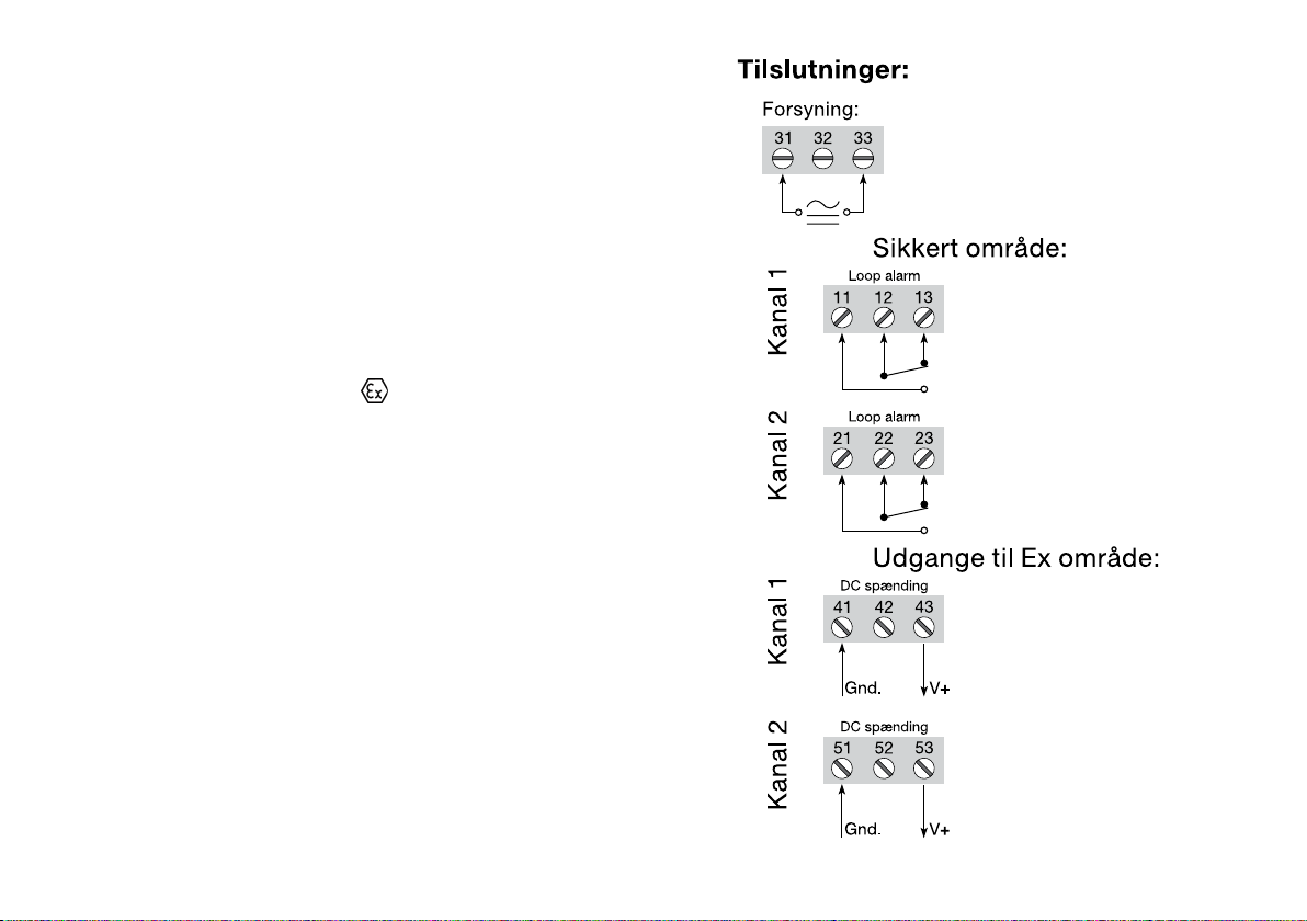
Connections:
Supply:
Channel 1Channel 2 Channel 2 Channel 1
Outputs for Ex area:
Safe area:
DC voltage
DC voltage
Loop alarm
Loop alarm
V+
Gnd.
V+
Gnd.
Input:
Supply voltage universal ............................. 21.6...253 VAC
50...60 Hz
19.2...300 VDC
Internal consumption .................................. ≤ 2 W (2 channels)
Max. consumption....................................... ≤ 4 W (2 channels)
Outputs:
Output voltage ............................................. > 18 VDC at 20 mA
Output current per channel (max.) .............. 28 mA
Relay outputs:
ON within limit ............................................. > 3.8...< 20.5 mA
Vmax ........................................................... 250 VRMS
Imax ............................................................. 2 ARMS
Max. AC output .......................................... 100 VA
Max. load at 24 VDC ................................... 1 A
EEx / I.S. approval:
DEMKO 99ATEX126256 .............................. II (1) GD
[EEx ia] IIC
Applicable for zone ..................................... 0, 1, 2, 20, 21 or 22
Ex / I.S. data:
Um ............................................................... : 250 V
Uo ................................................................ : 28 VDC
Io. ................................................................. : 93 mADC
Po ................................................................ : 0.65 W
Lo ................................................................. : 3 mH
Co ................................................................ : 0.08 µF
GOST R approval:
VNIIM & VNIIFTRI, Cert. no. ........................ See www.prelectronics.com
Observed authority requirements: Standard:
EMC 2004/108/EC ...................................... EN 61326-1
LVD 2006/95/EC .......................................... EN 61010-1
PELV/SELV ................................................... IEC 364-4-41 and EN 60742
ATEX 94/9/EC .............................................. EN 50014, EN 50020 and
EN 50281-1-1

24 25
ALIMENTATION Ex
PRepower 5420B
SOMMAIRE
Avertissements ................................................................... 26
Consignes de sécurité ....................................................... 27
Déclaration de conformité CE ............................................ 29
Démontage du SYSTEME 5000 ......................................... 30
Applications ........................................................................ 31
Caractéristiques techniques............................................... 32
Montage / installation ......................................................... 32
Applications ........................................................................ 32
Référence ........................................................................... 33
Spécifications électriques .................................................. 33
Connexions ........................................................................ 35
Schéma de principe ........................................................... 36
26 27
SIGNIFICATION DES SYMBOLES
Triangle avec point d’exclamation : Attention! Si vous ne
respectez pas les instructions, la situation pourrait être fatale.
Le signe CE indique que le module est conforme aux exigences des
directives.
Ce symbole indique que le module est protégé par une isolation double
ou renforcée.
L’utilisation des modules de type Ex avec des installations situées dans
des zones à risques d’explosions à été autorisée suivant la Directive ATEX.
CONSIGNES DE SECURITE
DEFINITIONS
Les gammes de tensions dangereuses sont les suivantes : de 75 à 1500 Vcc
et de 50 à 1000 Vca. Les techniciens sont des person nes qualifiées qui sont
capables de monter et de faire fonc tionner un appareil, et d’y rechercher les
pannes, tout en respectant les règles de sécurité. Les opérateurs, connaissant
le contenu de ce guide, règlent et actionnent les boutons ou les potentiomètres
au cours des manipulations ordinaires.
RECEPTION ET DEBALLAGE
Déballez le module sans l’endommager. Le guide doit toujours être disponible
et se trouver à proximité du module. De même, il est recommandé de conserver
l’emballage du module tant que ce dernier n’est pas définitivement monté. A
la réception du module, vérifiez que le type de module reçu correspond à celui
que vous avez commandé.
ENVIRONNEMENT
N’exposez pas votre module aux rayons directs du soleil et choisissez un
endroit à humidité modérée et à l’abri de la poussière, des températures
élevées, des chocs et des vibrations mécaniques et de la pluie. Le cas échéant,
des systèmes de ventilation permettent d’éviter qu’une pièce soit chauffée au-
delà des limites prescrites pour les températures ambiantes.
Tous les modules appartiennent à la catégorie d’installation Il, au degré de
pollution I et à la classe d’isolation Il.
MONTAGE
Il est conseillé de réserver le reccordement du module aux techniciens qui
connaissent les termes techniques, les avertis sements et les instructions de ce
guide et qui sont capables d’appliquer ces dernières.
AVERTISSEMENT !
Ce module est conçu pour supporter une connexion à des
tensions électriques dangereuses. Si vous ne tenez pas
compte de cet avertissement, cela peut causer des dommages
corporels ou des dégâts mécaniques.
Pour éviter les risques d’électrocution et d’incendie, conformez-
vous aux consignes de sécurité et suivez les instructions
mentionnées dans ce guide. Vous devez vous limiter aux
spécifications indiquées et respecter les instruc tions d’utilisation
de ce module, telles qu’elles sont décrites dans ce guide.
Il est nécessaire de lire ce guide attentivement avant de mettre
ce module en marche. L’installation de ce module est réservée
à un personnel qualifié (techniciens). Si la méthode d’utilisation
de l’équipement diffère de celle décrite par le fabricant, la
protection assurée par l’équipe ment risque d’être altérée.
AVERTISSEMENT !
Tant que le module n’est pas fixé, ne le mettez par sous tensions
dangereuses. Les opérations suivantes doivent être effectuées
avec le module débranché et dans un environnement exempt
de décharges électrostatiques (ESD) : démontage du module
pour régler les commutateurs DIP et les cavaliers, montage
général, raccordement et débranchement de fils et recherche
de pannes sur le module.
Seule PR electronics SARL est autorisée à réparer le module
et à remplacer les fusibles.
AVERTISSEMENT !
Il convient de monter l’appareil SYSTEM 5000 sur un rail DIN
en se conformant à la norme DIN 46277. Le connecteur de
communication du SYSTEM 5000 est relié aux borniers d’entrée
sur lesquelles peuvent se produire des tensions dangereuses.
Ce connecteur doit uniquement être raccordé à l’appareil de
programmation Loop Link au moyen du câble blindé.
TENSION
DANGE-
REUSE
INSTAL-
LATION
INFORMA-
TIONS
GENERALES

28 29
DECLARATION DE CONFORMITE CE
En tant que fabricant
PR electronics A/S
Lerbakken 10
DK-8410 Rønde
déclare que le produit suivant :
Type : 5420B
Nom : Alimentation Ex
correspond aux directives et normes suivantes :
La directive CEM (EMC) 2004/108/CE et les modifications subséquentes
EN 61 326-1
Pour une spécification du niveau de rendement acceptable CEM (EMC)
se référer aux spécifications électriques du module.
La directive basse tension 2006/95/CE et les modifications subséquentes
EN 61010-1
La directive ATEX 94/9/CE et les modifications subséquentes
EN 50014, EN 50020 et EN 50281-1-1
Certificat ATEX : Demko 99ATEX126256
Organisme notifié :
UL International Demko A/S
Lyskaer 8
P.O. Box 514
2730 Herlev
Danemark
Rønde, le 17 féverier 2010 Kim Rasmussen
Signature du fabricant
Si vous avez un doute quelconque quant à la manipulation du module, veuillez
contacter votre distributeur local. Vous pouvez également vous adresser à PR
electronics SARL, Zac du Chêne, Activillage, 4, allée des Sorbiers, F-69673
Bron Cedex (tél. : (0) 472 140 607) ou à PR electronics A/S, Lerbakken 10, DK-
8410 Rønde, Danemark (tél. : +45 86 37 26 77).
Le montage et le reccordement du module doivent être conformes à la
législation nationale en vigueur pour le montage de matéri aux électriques, par
exemple, diamètres des fils, fusibles de protection et implantation des modules.
Les connexions des alimentations et des entrées / sorties sont décrites dans le
schéma de principe de la fiche technique et sur l’étiquette de la face latérale du
module.
Les instructions suivantes s’appliquent aux modules fixes connectés en
tensions dangereu ses :
Le fusible de protection doit être de 10 A au maximum. Ce dernier,
ainsi que l’interrupteur général, doivent être facilement accessibles et
à proximité du module. Il est recommandé de placer sur l’interupteur
général une étiquette indiquant que ce dernier mettra le module hors
tension.
L’année de production ressort des deux premiers chiffres du numéro de série.
ETALONNAGE ET REGLAGE
Lors des opérations d’étalonnage et de réglage, il convient d’effectuer
les mesures et les connexions des tensions externes en respectant les
spécifications mentionnées dans ce guide.
Les techniciens doivent utiliser des outils et des instruments pouvant être
manipulés en toute sécurité.
MANIPULATIONS ORDINAIRES
Les opérateurs sont uniquement autorisés à régler et faire fonctionner des
modules qui sont solidement fixés sur des platines des tableaux, ect., afin
d’écarter les risques de dommages corporels. Autrement dit, il ne doit exister
aucun danger d’électrocution et le module doit être facilement accessible.
MAINTENANCE ET ENTRETIEN
Une fois le module hors tension, prenez un chiffon imbibé d’eau distillée pour
le nettoyer.
LIMITATION DE RESPONSABILITE
Dans la mesure où les instructions de ce guide ne sont pas strictement
respectées par le client, ce dernier n’est pas en droit de faire une réclamation
auprès de PR electronics SARL, même si cette dernière figure dans l’accord de
vente conclu.

30 31
ALIMENTATION Ex
PRepower 5420B
• Deux voies
• Isolation galvanique 5-port de 3,75 kVca
• Alimentation Ex > 18 V
• Surveillance de la boucle Ex
• Alimentation multi-tension ca ou cc
Applications :
• Alimentation de tension avec la barrière SI pour l’alimentation des modules
situés en zone dangereuse.
• Alimentation Ex avec surveillance de la boucle de courant.
Caractéristiques techniques :
• Le PR5420B dispose d’un relais par voie en zone non dangereuse. Les relais
s’ouvrent quand le courant de la boucle SI correspondante est en dehors des
limites prédéfinies.
• Alimentation et sorties sont flottantes et isolées galvaniquement.
Montage / installation :
• Pour montage vertical ou horizontal sur rail-DIN. 84 voies par mètre peuvent
être montées.
DEMONTAGE DU SYSTEME 5000
Tout d’abord, n’oubliez pas de démonter les connecteurs où règnent des
tensions dangereuses.
Figure 1 :
Débloquez le verrou inférieur pour
dégager le module du rail DIN.
Figure 2 :
Puis, débloquez le verrou supérieur
tout en extrayant la plaque avant :
la carte à circuits imprimés est alors
dégagée.
Vous pouvez maintenant régler les
commutateurs et les cavaliers.

32 33
Spécifications :
Plage de température :
-20°C til +60°C
Caractéristiques communes :
Fusible ......................................................... 400 mA T / 250 Vca
Tension d’isolation, test/opération .............. 3,75 kVca / 250 Vca
Température d’étalonnage .......................... 20...28°C
Taille max. des fils ....................................... 1 x 2,5 mm2 fil multibrins
Pression max. avant déformation
de la vis ....................................................... 0,5 Nm
Humidité relative.......................................... < 95% HR (sans cond.)
Dimensions (HxLxP) .................................... 109 x 23,5 x 130 mm
Rail DIN ....................................................... DIN 46277
Degré de protection .................................... IP20
Poids ........................................................... 215 g
Référence : 5420B
5420B Deux : 2
Type Voie
Immunité CEM ..................................................... < ±0,5%
Immunité CEM améliorée :
NAMUR NE 21, Critère A, burst .......................... < ±1%
Transmetteur 2-fils
Transmetteur 2-fils
Alarme
de boucle
Alarme
de boucle
Alimen-
tation
Alimen-
tation

34 35
31 32 33
53
51 52
23
21 22
11 12 13
43
41 42
Connexions :
Alimentation :
Voie 1Voie 2 Voie 2 Voie 1
Sorties vers la zone dangereuse :
Zone non dangereuse :
Tension cc
Tension cc
Alarme de boucle
Alarme de boucle
V+
Masse
V+
Masse
Entrée :
Tension d’alimentation multi-tension .......... 21,6...2530 Vca
50...60 Hz
19,2...300 Vcc
Consommation interne ............................... ≤ 2 W (2 voies)
Consommation max. .................................. ≤ 4 W (2 voies)
Sorties :
Sortie tension .............................................. > 18 Vcc à 20 mA
Sortie courant par voie (max.) ..................... 28 mA
Sorties relais :
Actif en dehors limite .................................. > 3,8...< 20,5 mA
V max .......................................................... 250 VRMS
I max ............................................................ 2 ARMS
Puissance ca max. ...................................... 100 VA
Charge max. à 24 Vcc ................................. 1 A
Approbation EEx / S.I. :
DEMKO 99ATEX126256 .............................. II (1) GD
[EEx ia] IIC
Applicable pour zone .................................. 0, 1, 2, 20, 21 ou 22
Caractéristiques SI :
Um ............................................................... : 250 V
Uo ................................................................ : 28 Vcc
Io. ................................................................. : 93 mAcc
Po ................................................................ : 0,65 W
Lo ................................................................. : 3 mH
Co ................................................................ : 0,08 µF
Approbation GOST R :
VNIIM & VNIIFTRI, Cert. no. ........................ Voir www.prelectronics.fr
Agréments et homologations : Standard :
CEM (EMC) 2004/108/CE ........................... EN 61326-1
DBT 2006/95/CE ......................................... EN 61010-1
PELV/SELV ................................................... IEC 364-4-41 et EN 60742
ATEX 94/9/CE .............................................. EN 50014, EN 50020 et
EN 50281-1-1

36 37
Ex-SPANNUNGSVERSORGUNG
PRepower 5420B
Inhaltverzeichnis
Warnung ............................................................................. 38
Sicherheitsregeln ................................................................ 39
EG-Konformitätserklärung .................................................. 41
Zerlegung des SYSTEMs 5000 .......................................... 42
Verwendung ........................................................................ 43
Technische Merkmale ......................................................... 43
Montage / Installation ......................................................... 43
Anwendungen .................................................................... 44
Bestellangaben ................................................................... 45
Elektrische Daten ............................................................... 45
Anschlüsse ......................................................................... 47
Blockdiagramm .................................................................. 48
Other manuals for 5420B
2
Table of contents
Languages:
Other PR electronics Power Supply manuals

PR electronics
PR electronics 2222 User manual

PR electronics
PR electronics 2220 User manual

PR electronics
PR electronics 2223 User manual

PR electronics
PR electronics 2223 User manual

PR electronics
PR electronics 2222 User manual

PR electronics
PR electronics 5420B User manual

PR electronics
PR electronics 2222 User manual

PR electronics
PR electronics 2220 User manual

PR electronics
PR electronics 9420 User manual

PR electronics
PR electronics 5420B User manual


