PRECILUM INGROUND 15 RGB User manual

INGROUND 15 RGB
INGROUND 24 RGB
INGROUND 31 RGBW
INSTRUCTIONS MANUAL
Round Square
DMX/RDM e ectronic on board
INGROUND Q 7 RGBW
DMX/RDM e ectronic on board
Round Square

TABLE OF CONTENTS
WWW.PRECILUM.COM
INGR. 15 RGB + INGR. 24 RGB + INGR. 31 RGBW + INGR. Q7 RGBW
INSTRUCTIONS MANUAL v1.1
1
1. INTRODUCTION
2. SAFETY AND OPERATION
3. INSTALLATION
4. CONNECTION DIAGRAMS
5. CARE AND MAINTENANCE
6. TECHNICAL SPECIFICATION
7. WARRANTY STATEMENT
2
4
5
15
17
18
19
FOR YOUR OWN SAFETY PLEASE READ THIS INSTRUCTION
MANUAL CAREFULLY BEFORE BEGINNING SETUP AND
INSTALLATION.
LED
E ectrostatic Sensitive Device
(EDS)

1. INTRODUCTION
2
The PRECILUM Inground range brings the INGROUND to the outdoor
world of exterior lighting With IP67 rating and drive over capability
these Inground fixtures are capable of meeting most exterior
applications
The refined thermal management system incorporates a sleek and
robust heat-sink directly into the fixture to ensure maximum heat
transfer and long life-time
The product is not suitable for environments with elevated salt content
(seaside environments, winter salting, etc ) Products from the "Marine"
range or stainless steel products are designed for this environment
1.1 About the product
WWW.PRECILUM.COM
INGR. 15 RGB + INGR. 24 RGB + INGR. 31 RGBW + INGR. Q7 RGBW
INSTRUCTIONS MANUAL v1.1

1. INTRODUCTION
3
INGROUND 15 RGB
INGROUND QUATTRO 7 RGBW
1.2 Dimensions
Ø207
111
100
Ø164
Ø187
SQUARE SHAPE 216x216
ROUND SHAPE Ø216
Ø249
116
103
Ø218
SQUARE SHAPE 260x260
ROUND SHAPE Ø260
INGROUND 24 RGB
INGROUND 31 RGBW
WWW.PRECILUM.COM
INGR. 15 RGB + INGR. 24 RGB + INGR. 31 RGBW + INGR. Q7 RGBW
INSTRUCTIONS MANUAL v1.1

2. SAFETY AND OPERATION
4
●Consider the respective national norms during the installation!
●Install this luminaire with properly prepared drainage under this
fixture,see installation page
●Drainage assure that fixture will not be sink in water IP67 !!! (its not
IP68)
●Do not install the fixture near the naked flames
●Do not install the fixture in dirty or dusty location
●Do not looking directly into the LED light beam at close range
●Turn off the power prior to light fixture installation!
●The light fixture may be installed only by a qualified person!
●The light fixture must be wired according to respective electrical
standards
●The manufacturer shall not be liable for any modifications of the
product of incorrect installation of the product
●Never install the luminaire on rain, fog or high humidity
CAUTION DANGEROUS VOLTAGE CONSTITUTING A RISK OF
ELECTRIC SHOCK IS PRESENT WITHIN THIS UNIT!
CAUTION THE POWER SUPPLY MUST BE UNPLUG FROM THE
MAINS POWER BEFORE CONNECTING ANY CABLES TO AVOID
DAMAGING THE PRODUCT!
CAUTION – FOR YOUR OWN SAFETY AVOID LOOKING DIRECTLY
INTO THE LED LIGHT SOURCE!
ANY PERSONS WHO INSTALLING THIS PRODUCT MUST BE
QUALIFIED FOR THE HANDLING OF ELECTRICAL
EQUIPMENT AND INSTALLATION MUST BE PERFORMED WITH
LOCAL STANDARTS AND REGULATIONS!
WWW.PRECILUM.COM
INGR. 15 RGB + INGR. 24 RGB + INGR. 31 RGBW + INGR. Q7 RGBW
INSTRUCTIONS MANUAL v1.1

3.1.1 Fixation of p astic s eeve
3. INSTALLATION
5
3.1 Hardware insta ation
●Prepare always 20-30 cm of drainage gravel and check that it works:
fill the tube of water and check that it completely disappear within
30 min If it doesn’t work study a further drainage system
●Aluminum sleeve must be installed on drainage layers, surrounding
concrete layers and leveled with external finish
CONCRETE WIRING
EXTERNAL FINISH
PLASTIC
SLEEVE
DRAINAGE
IP68 BOX/
CONNECTORS
MIN 200
WWW.PRECILUM.COM
INGR. 15 RGB + INGR. 24 RGB + INGR. 31 RGBW + INGR. Q7 RGBW
INSTRUCTIONS MANUAL v1.1

3. INSTALLATION
6
●Install the plastic sleeve
into the floor according
to Fig 1
●The edges of the plastic
sleeve must be flush
with the surrounding
floor
Fig 1
Fig 2
Fig 3
Fig 1
●Edges of the plastic
sleeve must not be
installed above the
surrounding floor
Fig 2
●Edges of the plastic
sleeve must not be
installed under the
surrounding floor
Fig 3
OK90°
NOT
ALLOWED
NOT
ALLOWED
WWW.PRECILUM.COM
INGR. 15 RGB + INGR. 24 RGB + INGR. 31 RGBW + INGR. Q7 RGBW
INSTRUCTIONS MANUAL v1.1

3.1.2 Fixation of fixture
3. INSTALLATION
7
Fig 4
Fig 5
Fig 6
●Remove the screws that
secure the stainless
steel face ring
Fig 4
●Remove the stainless
steel face ring
●Do not remove tempered
glass!!!
Fig 5
●Connect the cable
coming out of the
luminaire with the supply
IP 68 connector
(IN/OUT)/cable in the IP
juction box (more about
IP connection in 3 3 IP
BOX connection)
●Put the luminaire into the
plastic sleeve
Fig 6
Unscrew
CONNECTORS
/IP 68 BOX
WWW.PRECILUM.COM
INGR. 15 RGB + INGR. 24 RGB + INGR. 31 RGBW + INGR. Q7 RGBW
INSTRUCTIONS MANUAL v1.1

Tighten the screws
3. INSTALLATION
8
Fig 7
Fig 8
Fig 9
●Fasten the luminaire to
the plastic sleeve with
the enclosed screws
Fig 7
●Put on the stainless steel
front ring which you
removed in step 5 (Fig 5)
Fig 8
●Put on and tighten the
screws which you
removed in step 4 (Fig 4)
●Check if the screws are
tight properly!
Fig 9
Tighten the screws
WWW.PRECILUM.COM
INGR. 15 RGB + INGR. 24 RGB + INGR. 31 RGBW + INGR. Q7 RGBW
INSTRUCTIONS MANUAL v1.1

3. INSTALLATION
10
3.2.1 Wiring – IP 68 CONNECTOR IN/OUT, 48V DC option
3.2 Connection
MALE (IN) – Front view
+ 48V (red)
FEMALE (OUT) – Rear view (soldering)
- 48V (black)
POWER DMX
+ (red/white)
- (blue)
GND (grey)
MALE (IN) – Rear view (soldering)
+ 48V - 48V
+ 48V - 48V
+ 48V- 48V
+ 48V- 48V
-
+-
GND
+-
GND
+
GND
-
+
GND
FEMALE (OUT) – Front view
3 + 5 PIN
CONNECTOR
MALE (IN)
3 + 5 PIN
CONNECTOR
FEMALE (OUT)
WWW.PRECILUM.COM
INGR. 15 RGB + INGR. 24 RGB + INGR. 31 RGBW + INGR. Q7 RGBW
INSTRUCTIONS MANUAL v1.1

3. INSTALLATION
11
3.2 Connection
3.2.2 Wiring – IP 68 CONNECTOR option – DMX inter cab e
3 + 5 PIN
CONNECTOR
MALE
3 + 5 PIN
CONNECTOR
FEMALE
MALE (IN) – Front view FEMALE (OUT) – Front view
MALE (IN) – Rear view (soldering) FEMALE (OUT) – Rear view (soldering)
+ (red)
- (blue)
GND (grey)
DMX
-
+-
GND
+-
GND
+
GND
-
+
GND
WWW.PRECILUM.COM
INGR. 15 RGB + INGR. 24 RGB + INGR. 31 RGBW + INGR. Q7 RGBW
INSTRUCTIONS MANUAL v1.1
+ (red/white)

3. INSTALLATION
12
3.2.3 Wiring – IP 68 CONNECTOR option – Terminator connector
3.2 Connection
TERMINATOR
CONNECTOR
MALE
TERMINATOR
CONNECTOR
FEMALE
MALE (IN) – Front view FEMALE (OUT) – Front view
MALE (IN) – Rear view (soldering) FEMALE (OUT) – Rear view (soldering)
Resistor 120 OHM
120 OHM 120 OHM
WWW.PRECILUM.COM
INGR. 15 RGB + INGR. 24 RGB + INGR. 31 RGBW + INGR. Q7 RGBW
INSTRUCTIONS MANUAL v1.1

POWER
Wire L (Live): black/brown
Wire N (Neutral): dark blue
Wire PE (Earth): yellow/green
3. INSTALLATION
13
3.2.4 Wiring – Open cab e, 230V AC option
3.2 Connection
LN
PE
DMX
+
-
GND
Wire + (DMX): white/red
Wire – (DMX): light blue
Wire GND (DMX): grey
DMX
WWW.PRECILUM.COM
INGR. 15 RGB + INGR. 24 RGB + INGR. 31 RGBW + INGR. Q7 RGBW
INSTRUCTIONS MANUAL v1.1

If it is not a version with IP68 connectors use a SCAME IP box or
similar (not included)
Must be made a waterproof connection of at least IP68 We strongly
recommend to use special two components silicone GEL for sealing
junction boxes containing electrical connections If the IP rating of the
connection is not observed, the complaint will not be accepted!
For example:
https://www etelec com/prodotto/mpgel/
Video tutorial:
https://wwwyoutube com/watch?v=tj6ksKdzuE0
PRECILUM requirement:
3. INSTALLATION
14
3.3 IP BOX connection
WWW.PRECILUM.COM
INGR. 15 RGB + INGR. 24 RGB + INGR. 31 RGBW + INGR. Q7 RGBW
INSTRUCTIONS MANUAL v1.1

4. CONNECTION DIAGRAMS
15
4.1 IP 68 CONNECTOR, 48V DC option
12 3 16
32 31 17
JUNCTION
BOX
DMX INTER CABLE
DMX
CABLE
JUNCTION
BOX
CONNECTOR MALE CONNECTOR FEMALE
COMBI CABLE
JUNCTION BOX
DMX CABLE
POWER
CABLE
48V
COMBI
CABLE
DMX
POWER
++
GND
++
POWER SUPPLY
Input 230V AC 50Hz
Output 48 V DC
POWER SUPPLY
Input 230V AC 50Hz
Output 48 V DC
TERMINATOR CONNECTOR:
SPECIAL CONNECTOR WITH RESISTANCE OF 120 ohms
COMBI CABLE
COMBI CABLE
DMX CONTROLLER
(See accessories)
DESCRIPTION
CONNECTORS (MALE/FEMALE)
LUMINAIRE
* QTY OF LUMINAIRES IN DAISY CHAIN (ACCORDING ELEC. DESIGNER CALCULATION)
** QTY OF THE DMX LUMINAIRES IN ONE STRING MAX. 32 PIECES
WWW.PRECILUM.COM
INGR. 15 RGB + INGR. 24 RGB + INGR. 31 RGBW + INGR. Q7 RGBW
INSTRUCTIONS MANUAL v1.1

4. CONNECTION DIAGRAMS
16
4.2 Open cab e, 230V AC option
12 3 16
32 31 30 17
JUNCTION
BOX
JUNCTION
BOX
JUNCTION
BOX
230 V AC 50 Hz
JUNCTION
BOX
JUNCTION
BOX
JUNCTION
BOX
JUNCTION
BOX
JUNCTION
BOX
DMX CABLE SIGNAL
230V AC 50Hz
DMX CONTROLLER
(See a essories)
TERMINATOR CONNECTOR:
SPECIAL CONNECTOR WITH RESISTANCE OF 120 ohms
DMX CABLE SIGNAL
230V AC 50Hz
DMX CABLE SIGNAL
230V AC 50Hz
DMX CABLE SIGNAL
230V AC 50Hz
DMX CABLE SIGNAL
+
230V AC 50Hz
DMX CABLE SIGNAL
+
230V AC 50Hz
DMX CABLE SIGNAL
+
230V AC 50Hz
DMX CABLE SIGNAL
+
230V AC 50Hz
DMX CABLE SIGNAL
+
230V AC 50Hz
DMX CABLE SIGNAL
+
230V AC 50Hz
DMX CABLE SIGNAL
+
230V AC 50Hz
DMX CABLE SIGNAL
+
230V AC 50Hz
DESCRIPTION
TERMINATOR CONNECTOR
LUMINAIRE
* QTY OF THE DMX LUMINAIRES IN ONE STRING MAX. 32 PIECES
WWW.PRECILUM.COM
INGR. 15 RGB + INGR. 24 RGB + INGR. 31 RGBW + INGR. Q7 RGBW
INSTRUCTIONS MANUAL v1.1

Clean the front transparent cover at least every 6 months Use a moist,
lint-free cloth Never use alcohol or solvents
A scheduled maintenance programme must be carried out on the
installation and the fittings regardless of their IP rating or application –
these must include the following operations:
●Clean the fittings from dirt that may be deposited on the protection
grills and in the heads of the screws by following the installation
instructions attached to each fi tting
● Check that the screws are not loose on the various components of
the luminaire (glass frame, cable entry , … )
● Check each cable gland, and cable for damage and that the cable
gland has not come loose
● For each Isolation Class 1 fitting check that the earth cable has not
come loose The clip must not show signs of oxidation,damage or
become loose
● For class 2 fittings check any eventual plastic / isolating covering in
order to verify any damage
●Check that all the seals are in good condition and that they are not
dry, damaged or split
●Check the glass or plastic screen for damage and replace if required
●Check for water inside the luminaire’s housing and its recessing box
The internal components such as the ballasts, transformers, washers
and screws must not show clear signs of oxidation or rust
Clear traces of rust and oxidation will indicate the presence of water
inside the luminaire
In case of damage the components must be replaced by original
components and spare parts before using the fi tting
We also recommend to check the fitting each time the lamp is replaced
or at least once a year or within the prescribed maintenance schedule
period depending on the type of installation
5. CARE AND MAINTENANCE
17
PRECILUM™ PRODUCTS ARE OF SUPERIOR DESIGN AND
QUALITY AND SHOULD BE TREATED WITH CARE. THE
RECOMMENDATIONS BELOW WILL HELP FULFILL GAIN GOOD
USE AND LONGEVITY FROM THE PRODUCTS.
WWW.PRECILUM.COM
INGR. 15 RGB + INGR. 24 RGB + INGR. 31 RGBW + INGR. Q7 RGBW
INSTRUCTIONS MANUAL v1.1

Ground recessed
INGR 15 RGB, INGR 24 RGB, INGR 31 RGBW
Spot, Narrow, Medium, Wide, Flood, Oval, Assym
INGROUND QUATTRO 7 RGBW
Narrow, Oval
High power OSRAM LEDs
RGB, RGBW, RGBA and other accor req
See datasheet
230V 50Hz AC or 48V DC
DMX/RDM electronic on board
INGROUND 15 RGB
15W (current 350mA) / 23W (current 500mA)
INGROUND 24 RGB
24W (current 350mA) / 36W (current 500mA)
INGROUND 31 RGBW
31W (current 350mA) / 47W (current 500mA)
INGROUND QUATTRO 7 RGBW
xxW (current 350mA) / xxW (current 500mA)
70 000 hrs /L70 @25°C
-20°C/+40°C
Housing: die cast aluminium
Cover: clear hardened glass+ stain steel face ring
See dimensional drawing
IP67
INGROUND 15 RGB + INGROUND Q 7 RGBW: 2,8 kg
INGROUND 24 RGB + INGROUND 31 RGBW: 4,9 kg
See website
6. TECHNICAL SPECIFICATION
18
Mounting:
Optical system:
LED device:
LED colour:
Lumen output:
Input voltage:
Control:
Max power conpusion:
Service lifetime:
Operation ambient temp:
Materials:
Dimensions:
Enviroment:
Weight:
Accesories:
WWW.PRECILUM.COM
INGR. 15 RGB + INGR. 24 RGB + INGR. 31 RGBW + INGR. Q7 RGBW
INSTRUCTIONS MANUAL v1.1

7. WARRANTY STATEMENT
19
Precilum provides a product warranty for a period of five (5) years
from date of purchase
The product is not suitable for environments with elevated salt content
(seaside environments, winter salting, etc ) Products from the "Marine"
range or stainless steel products are designed for this environment
Failure to comply with these conditions will not be accepted as a
warranty complaint
Please refer www precilum com for all warranty terms and conditions
WWW.PRECILUM.COM
INGR. 15 RGB + INGR. 24 RGB + INGR. 31 RGBW + INGR. Q7 RGBW
INSTRUCTIONS MANUAL v1.1
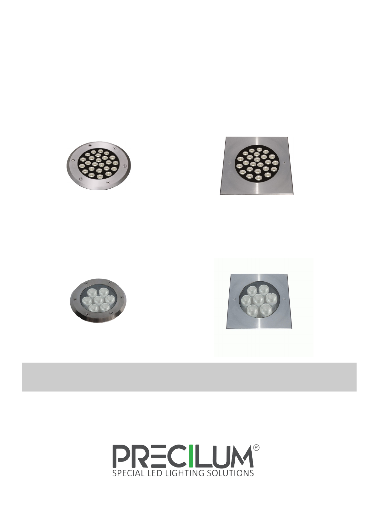
This manual suits for next models
3
Table of contents
Other PRECILUM Outdoor Light manuals