manuals.online logo
Brands
  1. Home
  2. •
  3. Brands
  4. •
  5. Tekmar
  6. •
  7. Controllers
  8. •
  9. Tekmar D 255 User manual

Tekmar D 255 User manual

1
Item
Date
S/N
5
Pump /
Boiler 2
2
1
6
34
Boiler 1
No Power
789
Com
Sen Sup
SenOut
Sen
24 V Only
21
CR
Power
H11121
PRGM
FC
1
2
Min.
Outdoor
Supply
Target Supply
Curve
WWSD
Differential
Two Stage Boiler
Control 255
Nº of boilers
Power Supply:
24V 60Hz 3VA
Relay Capacities:
120V 10A 1/3hp
- Data Brochure
Two Stage Boiler Control 255 06/94
D 255
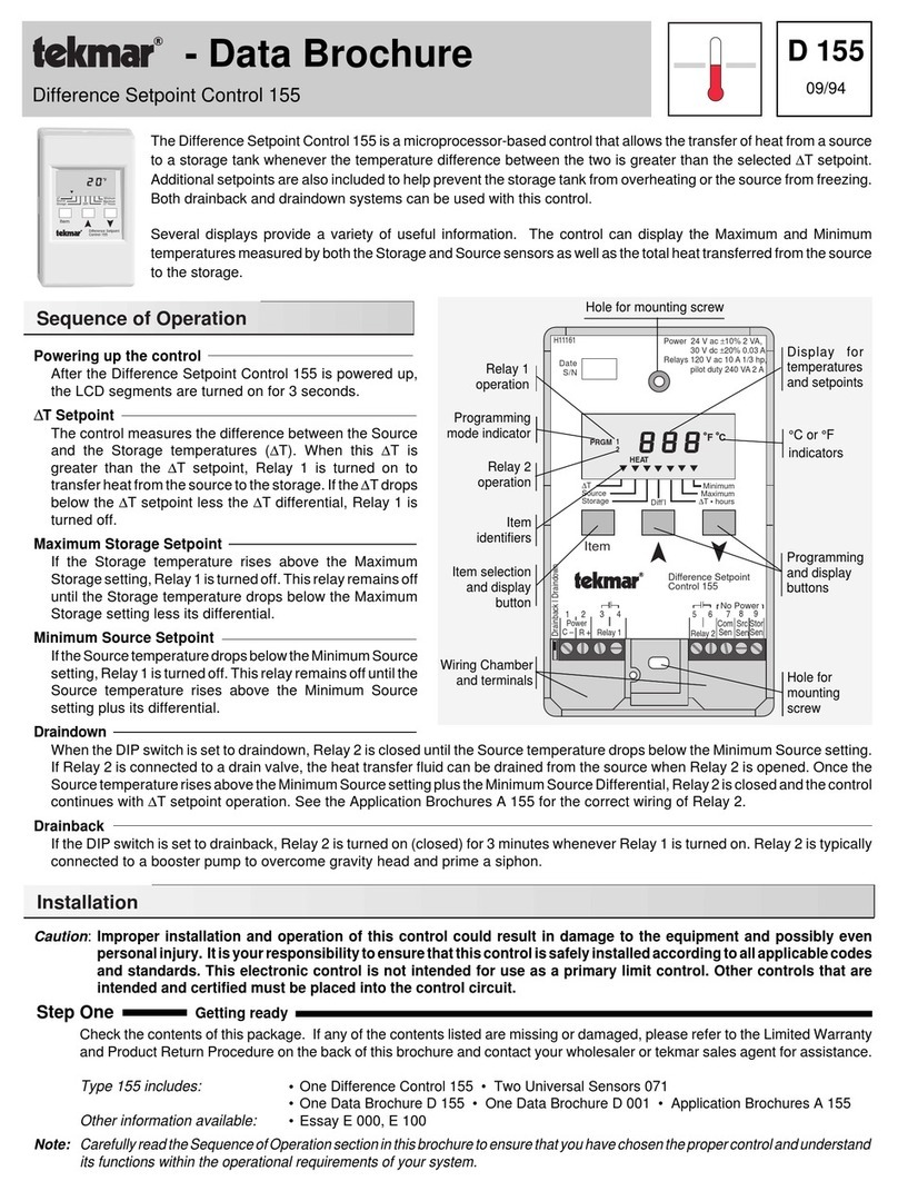
ThetekmarTwoStageBoilerControl255isamicroprocessor-basedoutdoorresetcontrolthatisdesignedtoregulate
the supply water temperature from one or two boilers based on the outdoor air temperature. If one boiler is used, a
system pump output is available.
The control has programmable settings for minimum supply temperature, differential, heating curve, and warm
weather shut down temperature. The control has a digital liquid crystal display (LCD) window that normally shows
the outdoor temperature and can be used to display supply, target supply and programmable settings.
The Two Stage Boiler Control 255 is a cost effective answer for outdoor reset of many single and dual boiler applications
.
Wiring Chamber;
Terminals for
Sensor(s)
Wiring Chamber;
Terminals for 24Vac
power supply and
control circuit
for boiler(s) /
pump
Hole for mounting screw
Programming
mode indicator
Item
identifiers
Item selection and
display button
Temperatures,
Heating Curve and
Differential
Display
Boiler(s)
operation
Sequence of Operation
•
When the Two Stage Boiler Control 255 is
powered-up, the digital display will show all of
the display elements. The control will then
monitortheoutdoortemperatureanddisplayit
on the digital display. Pressing and releasing
the Item button will toggle to the supply tem-
perature. Pressing and releasing the Item
button again will toggle the display to the
Target Supply temperature.
•
If the outdoor temperature is warmer than the
WWSD point, the "WWSD" pointer will flash on
andoff,andthecontrolwillkeeptheboiler(s)off.
•
If the outdoor temperature is colder than the
WWSDpoint, thecontrolcalculatesthedesired
supplytemperaturebasedon the requirements
of the Heating Curve or on the Boiler Minimum
setting, whichever is greater.
If the Boiler Mini-
mum setting is higher than the Heating Curve
requirement,
the"Min."pointerwill flash on and
off and the control will maintain the supply
temperature at the Boiler Minimum setting.
If
the outdoor temperature is cold enough to
operateontheHeatingCurve,
the"Min"pointer
will turn off, and the control will maintain the
supplywatertemperatureattheHeatingCurve
desired temperature.
°C or °F
indicators
Programming
buttons
Outdoor Reset Strategy
Heating Curve
As the outdoor temperature becomes colder heat losses from a building increase, requiring more heat
be added to prevent the indoor temperature from also becoming colder. This tekmar reset control
measures the outdoor temperature and, as it becomes colder, the control balances the heat loss by
makingtheheatingsupplywaterhotter.
TheHeatingCurveisusedtocalculateexactlyhowhottomake
the supply water at different outdoor temperatures. It determines the number of degrees the supply
water temperature is raised for each degree the outdoor temperature falls.
•
IftheHeatingCurveselectedistoolow,
thesupplytemperaturewillnotbehotenoughtokeeptheroom
temperature warm during cold weather.
•
If the Heating Curve selected is too high,
the supply temperature will be hotter than necessary and
energy will be wasted.
Outdoor air temperature
Supply water temperature
50
(10) 30
(-1) 10
(-12) -10°F
(-23)°C
110
(43)
70
(21)
70
(21)
90
(32)
210
(99)
170
(77)
150
(65)
130
(54)
190
(88)
3.6 3.0 2.4 2.0 1.6
0.8
0.4
1.0
0.6
90
(32)
50°F
(10)°C
Heating
Curve
WWSD
Point
1.2
F
Two Stage Boiler
Control 255
Min.
Item
Outdoor
Supply
TargetSupply
Curve
WWSD
Differential
• Thereisaminimumtimedelaybetweenaboiler
being turned off and then back on. For the first
boiler, this time is preset to 30 seconds. When
two boiler operation is selected, the delay be-
tween the boiler stages is adjustable from 30
seconds to 4 minutes.
• Toobtainthe best operationfromaresetcontrol,itisimportanttomeasurethe system supplytemperatureasaccuratelyaspossible.
Wheneverthe control isenergized,the systempump mustoperateto maintaincontinuouswater flow acrossthesupply temperature
sensor. Refer to the application drawings A 255 for plumbing concepts.
2
Caution
Improperinstallationandoperationofthis controlcould resultin damageto theequipment andpossibly evenpersonal
injury. It is your responsibility to ensure that this control is safely installed according to all applicable codes and
standards. This electronic control is not intended for use as a primary limit control. Other controls that are intended
and certified as safety limits must be placed into the control circuit.
Step One Getting ready
Check the contents of this package. If any of the contents listed are missing or damaged, please refer to the Limited Warranty
and Product Return Procedure on the back of this brochure and contact your wholesaler or tekmar sales agent for assistance.
Type 255 includes:
•One Two Stage Boiler Control 255 • One Outdoor Sensor 070 • One Supply Sensor 071
• One Data Brochure D 255 • One Data Brochure D 001 • Application Brochures A 255
Other information available:
• Essay E 000 • Essay E 200
Read Application Brochures A 255 and select the correct Application for your job.
Note
:
Carefully read the details of the Application, and the Sequence of Operation section in this brochure to ensure that you have
chosen the proper control, and understand its functions within the operational requirements of your system.
Step Two
Mounting
The control is mounted in accordance with the instructions in the Data Brochure D 001.
Step Three
Rough-in wiring
All electrical wiring terminates in the two wiring chambers at the bottom front of the control. If the control is to be mounted on
an electrical box, the wiring can be roughed-in at the electrical box prior to installation of the control (see Brochure D 001).
Standard 18 AWG solid wire is recommended for all low voltage wiring to this control.
Caution: Power should not be applied to any of the wires during this rough-in wiring stage.
• Install the Outdoor Sensor 070 and the Supply Sensor 071 according to the instructions in Data Brochure D 001 and run the
wiring back to the control.
• Installa24VacClassIItransformerwithaminimum5VAratingandrunthewiringfromthetransformer tothecontrol.
AClass
II transformer must be used. Do not connect any of the transformer terminals to ground.
• Install the wiring from the boiler(s) and pump circuits to the control.
Step Four
Testing and connecting the wiring
Caution
These tests are to be performed using standard testing practices and procedures and should only be carried out by a properly
trained and experienced person. A good quality electrical test meter, capable of reading from at least 0 — 200 Volts ac and at
least0—2,000,000Ohms,isessentialtoproperlytestthiscontrol. Atnotimeshouldvoltagesinexcessof28Vacbemeasured
at any of the wires connected to the control.
Warm Weather Shut Down (WWSD)
This control shuts off the boiler(s) when the outdoor temperature is above the WWSD point and heat is no longer needed. When
the correct WWSD point has been selected, overheating is prevented and comfort and energy savings are increased. When the
outdoortemperaturecoolsoffagain,the heating system is turned onat the WWSD point tostart delivering heat. The WWSD point
is usually the desired room temperature in the building, however internal heat gains (from appliances, people, etc.) can change
heat requirements and a lower WWSD point may be selected through trial and error.
• When the system is operating near the WWSD point and the building is too cold,
the WWSD point should be raised.
• When the system is operating near the WWSD point and the building is too warm,
the WWSD point should be lowered.
Installation
Test the sensors
Thesetestsmustbeperformed
before
powerisappliedtothecontrol and
before
thesensorsareconnectedtothe terminal strip.
Test both sensors according to the instructions printed in the Data Brochure D 001.
Test the power supply
• Ensure that the wires from the power supply transformer are not touching each other, any other wires or ground. Turn on the
power, and using an AC voltmeter, you should measure between 20 and 28 volts at the secondary side of the transformer.
• Turn off the power and complete the electrical connections to the terminal strips of the control.
24 V Only No Power
24Vac
power
supply
Closes to
operate Boiler
#1
Closes to
operate pump
or Boiler #2
DIP
Switch
1
C2
R34
10A 10A
Boiler 1 Pump /
Boiler 2
567
Com
Sen Sup
Sen Out
Sen
89
Supply
Sensor
#1 (071) Outdoor
Sensor
#2 (071)
Power
2
1
Nº of boilers
Power and output connections Caution, Maximum 24 Volts
Connect the transformer to terminals
Power C—R
(1 and 2).
Connect the boiler #1 circuit to terminals
Boiler 1
(3 and 4)
• Iftwoboilers(stages)aretobeoperated, slide the DIP switch to the "2"
position and wire boiler #2 to terminals
Pump / Boiler 2
(5 and 6). For
single boiler operation, slide the DIP switch to the "1" position and wire
the system pump circuit to terminals
Pump / Boiler 2 (5 and 6).
Sensor connections Caution, never apply power to these terminals.
Connect theOutdoor Sensor 070 toterminals
ComSen — OutSen
(7 and 9).
ConnecttheSupplySensor 071toterminals
ComSen—SupSen
(7and8).
3
Heating Curve
To calculate the correct setting for the design supply temperature –WWSD temperature
Heating Curve, use the following formula: WWSD temperature – design outdoor temperature
For example: • design outdoor temperature = 5°F (-15°C)
• WWSD temperature = 70°F (21°C) Heating Curve = = = 1.4
• design supply temperature = 160°F (71°C)
If the system design supply water temperature is unknown, a trial setting can be calculated using these typical supply temperatures:
• Fan coils or convectors …180 to 210°F (82 to 99°C) • Hydronic radiant floors …100 to 130°F (38°to 54°C).
Warm Weather Shut Down (WWSD)
TheWWSD canbeadjustedfrom35to105°F(2to41°C)anditsfunctioniscoveredundertheOutdoorResetStrategysectiononpage 2.
If the DIP switch is selected for one boiler operation, the pump output will cycle on for 20 seconds every three days during WWSD.
Minimum Boiler Operating Temperature
This adjustment should be set according to the requirements specified by the boiler
manufacturer. Many boilers require a minimum operating temperature to prevent
corrosion from flue gas condensation. The control raises the supply temperature to the
Minimum when the outdoor temperature drops below the WWSD setting, and holds it
there until the outdoor temperature becomes cold enough to require operation on the
heating curve.
Typical Minimum Boiler Operating Temperatures: • Steel Tube Boilers …140°to 180°F (60°
to82°C)•CastIronBoilers…130to150°F(54to66°C)•CopperTube Boilers …105to 150°F
(41 to 66°C) • Condensing or Electric Boilers …off
Settings
Desired temperature
this example
160°F(71°C)
Temperature
WarmerCooler
Time
Differential
this example
10°F(5°C)
165°F(74°C)
155°F(68°C)
Temperaturefall
BOILER
OFF ON
Temperaturerise
Heating Curve =
Outdoor air temperature
Supply water temperature
50
(10) 30
(-1) 10
(-12) -10°F
(-23)°C
110
(43)
70
(21)
70
(21)
90
(32)
210
(99)
170
(77)
150
(65)
130
(54)
190
(88)
3.6 3.0 2.4 2.0
0.8
0.4
1.0
0.6
90
(32)
50°F
(10)°C
Heating
Curve
1.2
Minimum Supply
Setting 130°F
WWSD
Point
70°F
1.6
The control automatically goes back to viewing when the buttons are left alone for 20 secondsThe control automatically goes back to viewing when the buttons are left alone for 20 seconds
When the control is
powered-up, all display
elements are turned on.
After approximately 3
seconds, the control
automatically goes into
operating mode.
POWER ON
PROGRAMMING
Push or to change
minumum boiler staging
delay
Push or to
change Heating Curve
(underscore is decimal point)
When in operating mode,
the Outdoor temperature
will be displayed. Boiler(s)
output is on when number
segment is on. When
number is flashing, delay
on is occuring.
Item
VIEWING
Press and Release
the
"Item" button. The
programmed Differential
setting will be displayed.
Item
Press and Release
the
"Item" button. The
programmed Warm
Weather Shut Down
setting will be displayed.
Item
Item
Press and Release
the
"Item" button. The Target
Supply temperature will be
displayed.
Press and Release
the
"Item" button. The
programmed Minimum
supply temperature setting
will be displayed. A fast
flashing pointer indicates
programming is active.
Item
Press and Release
the
"Item" button. The
programmed Heating
Curve setting will be
displayed.
Push or to select between
Fahrenheit or Celsius scales
Press and Release
the
"Item" button. The
Fahrenheit or Celsius
scale may be selected.
Item
Press and Release
the
"Item" button. Only with two
boiler option will the minimum
boiler staging delay be
displayed.
Push or to
change Differential
Push or to
change WWSD setting
Min.
Outdoor
Supply
Target Supply
Curve
WWSD
Differential
Min.
Outdoor
Supply
Target Supply
Curve
WWSD
Differential
Min.
Outdoor
Supply
Target Supply
Curve
WWSD
Differential
Min.
Outdoor
Supply
Target Supply
Curve
WWSD
Differential
Min.
Supply
Outdoor
Target Supply
Curve
WWSD
Differential
Min.
Outdoor
Supply
Target Supply
Curve
WWSD
Differential
Min.
Supply
Outdoor
Target Supply
Curve
WWSD
Differential
Min.
Supply
Outdoor
Target Supply
Curve
WWSD
Differential
Min.
Outdoor
Supply
Target Supply
Curve
WWSD
Differential
Item
F
1
PRGM
F
PRGM
F
Min.
Outdoor
Supply
Target Supply
Curve
WWSD
Differential
When only one boiler is
selected, the Pump output
contact will be on
continuously until WWSD
occurs. A slow flashing
pointer indicates control
action.
F
1
Press and Release
the
"Item" button. The Supply
temperature will be
displayed.
Item
Push or to
change Minimum supply
temperature
PRGM
PRGM
PRGM
F
PRGM
The display defaults to
outdoor temperature after
power up, or if the control
has been left alone in
programming longer than
20 seconds.
Item
Min.
Outdoor
Supply
Target Supply
F
1
Curve
WWSD
Differential
Min.
F
1
Curve
WWSD
Differential
Outdoor
Supply
Target Supply
F
1
2
PRGM
FC
1
2
F
= 10°F (6°C)
Differential and Time Delay
Thedifferentialadjustmentsetshowfartheactualsupplywatertemperaturemaydeviate
fromthe desiredtemperature beforeaboiler isturnedon oroff, andisdetermined bythe
flowratethroughthesystem pumprelativetotheamountofheatproduced. Whenusing
twoboilers, boiler #2will be stagedonwhen the actualsupplytemperature drops below
thecontrol'scalculatedtargetsupplyminusthedifferentialsetting. Note: Boiler#2delay
time must have expired before boiler # 2 is fired. To prevent short boiler cycles, the
controlhas a minimum timedelayof 30 secondsbetweenfiringcycles for thefirstboiler.
Whentwoboiler operation is selected, theminimumdelaybetween stages is adjustable
from 30 seconds to 4 minutes.
In the following example, boiler # 1 will turn on when the actual temperature falls 5°F
(3°C) below the desired temperature and will turn off when the actual temperature rises
5°F (3°C) above the desired temperature.100,000 Btu/hr
20 US GPM x 500
=
Differential = Btu/hr of each stage
System US GPM x 500
90°F
65°F
160°F - 70°F
70°F - 5°F
4
Two Stage Boiler Control 255
Literature — D 255, A 255, D 001, E 000, E 200
Control — Microprocessor PI control; This is not a safety (limit) control.
Packaged weight — 1.0 lb. (450 g), Enclosure C, PVC plastic
Dimensions — 4-3/4” H x 2-7/8” W x 7/8” D (120 x 74 x 22 mm)
Approvals — Meets DOC regulations for EMI/RFI.
Ambient conditions — Indoor use only, 15 to 120°F (-10 to 50°C), < 90% RH non-
condensing.
Power supply — Class 2, 24 V ac ±10% 50/60 Hz 3 VA
Relays — 120 V ac 10 A 1/3 hp, pilot duty 240 VA 2 A
Sensors — NTC thermistor, 10 kΩ@ 25°C ±0.2°C ß=3892
included: Outdoor Sensor 070 and Universal Sensor 071.
Control accuracy — ±0.5°F (±0.25°C) with up to 1000 feet (300m) of 18AWG wire
to sensors.
Min. Boiler Supply
— Off, 70 to 170°F (Off, 21 to 77°C)
Differential
— 2 to 45°F (1 to 25°C)
WWSD
— 35 to 105°F (2 to 41°C)
Heating Curve
— 0.4 to 3.6
Stage 2 Delay
— 0:30 to 4:00 minutes
In North America: tekmar Control Systems Ltd., Canada
tekmar Control Systems, Inc., U.S.A.
Head office: 4611 - 23rd Street
Vernon, B.C. Canada V1T 4K7
Tel. (604) 545-7749 Fax. (604) 545-0650
All specifications are subject to change without notice.
Printed in Canada on recycled paper.
Product designs, software and literature are Copyright © 1994 by:
tekmar Control Systems Ltd. and tekmar Control Systems, Inc.
Limited Warranty: tekmar warrants to the original purchaser each tekmar product against defects
in workmanship and materials when the product is installed and used in compliance with tekmar's
instructions. Thislimited warranty covers the cost of parts andlabour provided by tekmar to correct
defects in materials and/or workmanship. Returned products that are fully operational are not
considered a warranty case. tekmar also does not cover parts or labour to remove, transport or
reinstall a defective product. tekmar will not be liable for any damage other than repair or
replacementof the defective part or parts and such repairorreplacementshall be deemed to be the
sole remedy from tekmar. This warranty shall not apply to any defects caused or repairs required
asaresultofunreasonableornegligentuse,neglect,accident,improperinstallation,orunauthorized
repairoralterations. Incaseofdefect,malfunction or failure to conform to warranty, tekmar will, for
a warranty period of 24 months from the date of invoice to the original purchaser or 12 months from
the date of installation of the product, whichever occurs first, repair, exchange or give credit for the
defective product. Any express or implied warranty which the purchaser may have, including
merchantabilityandfitnessforaparticularpurpose,shallnotextendbeyond24monthsfromthedate
of invoice or 12 months from the date of installation of the product, whichever occurs first.
Replacements:tekmarcansendreplacementproductsifrequested. Allreplacementsareinvoiced.
Any possible credit for the replacement will only be issued once the replaced product has been
returned to tekmar.
Product Return Procedure: Products that are believed to have failed must be returned to tekmar
Control Systems Ltd. 4611-23rd Street, Vernon B.C. Canada V1T 4K7 when agreed to by tekmar.
The installer or other qualified service person must, at the owner's expense, determine which
Limited Warranty and Product Return Procedure
IftroubleshootingbecomesnecessarywiththeTwoStageBoilerControl255,followthetestingprocedureinstepfouroftheinstallation
procedure on page 2 of this brochure.
If the display window is flashing “Err” and the outdoor pointer, the outdoor sensor is either open or short circuit. The control is
programmedtoassumean outdoor temperature of 32°F (0°C)andcontrolthesupplytemperatureaccordingly. Ifthedisplaywindow
isflashing “Err” and thesupplypointer,the supply sensoris eitheropen orshort circuit. Ifthis typeof faultoccurs, thecontrol will turn
off its relays in order to shut down the heating equipment it is controlling.
If you do not think the control is operating properly, check to see that the settings have been made correctly and that the problem is
not a result of external causes. Make sure that all wiring connections are solid and the sensors are correctly located.
Testing and Troubleshooting
Technical Data
Before you leave
• Install the wiring cover over the wiring chamber and secure it with the screw provided. • Place the front cover on the control and
snap it into place. • Place this brochure, and all other brochures relating to the installation, in the protective plastic bag supplied with
the control. • Place the bag in a conspicuous location near the control for future reference. • It is important to explain the operation
of this control within the system to the end user, and anyone else who may be operating the system.
Item
Date
S/N
5
Pump /
Boiler 2
2
1
6
34
Boiler 1
No Power
789
Com
Sen Sup
SenOut
Sen
24 V Only
21
CR
Power
H11121
PRGM
FC
1
2
Min.
Outdoor
Supply
Target Supply
Curve
WWSD
Differential
Two Stage Boiler
Control 255
Nº of boilers
Power Supply:
24V 60Hz 3VA
Relay Capacities:
120V 10A 1/3hp
The installer must ensure that this control and its wiring are isolated and/or shielded from strong sources of
electromagnetic noise. Conversely, this control does not exceed the Class B limits for radio noise emissions
from digital apparatus as set out in the Radio Interference Regulations of the Canadian Department of Communications. If this equipment does cause
interference, the user is encouraged to try and correct the interference by reorienting the receiving antenna and/or relocating the receiver with respect to
this equipment. Le présent numérique n’émete pas de bruits radioeléctriques dépassant les limites applicables aux appareils numériques de Classe B
prescrites dans le réglement sur le brouillace radioeléctrique édicté par le Ministére des Communications du Canada.
component has failed. The product must be returned complete withall of its components (sensors,
base,etc.). Products must be returned together with the proof of purchase to theoriginalpurchaser
whothen returns theproductto tekmar afterreceivinga Return Goods Authorization(RGA)number
from tekmar.
Pleaseinclude thefollowing information withthe product. The fulladdress oftheoriginal purchaser,
the RGA number and a description of the problem.
Fromthe U.S.A., in ordertoavoidcustoms charges, products must bereturnedvia US Post with the
package clearly marked with the RGA number, product type and the statement "Canadian Product
returned for
repair". For shipping purposes the product can be valued at one half list price.
1) If returned during the warranty period and the product is defective, tekmar will issue full credit
for the returned product less cost of missing parts.
2) Ifreturned during thewarrantyperiod and the productisfully operational, tekmar willreturnthe
product to the original purchaser for a testing cost of $30.00 plus postage.
3) If returned during the warranty period and the product is not damaged and is fully opera
tional, tekmar can take back the product for a return charge of 40% of the product's net value.
This request has to be specified otherwise the product will be returned with a testing cost of
$30.00 plus postage.
4) Ifreturned after the warranty period and the product needs repair, tekmar willrepairandreturn
the product. Repair and postage costs will be invoiced. tekmar's repair costs are calculated
at $30.00 / hour plus the cost of parts. If the repair costs will be more than $60.00 a repair
estimate will be sent to the original purchaser.

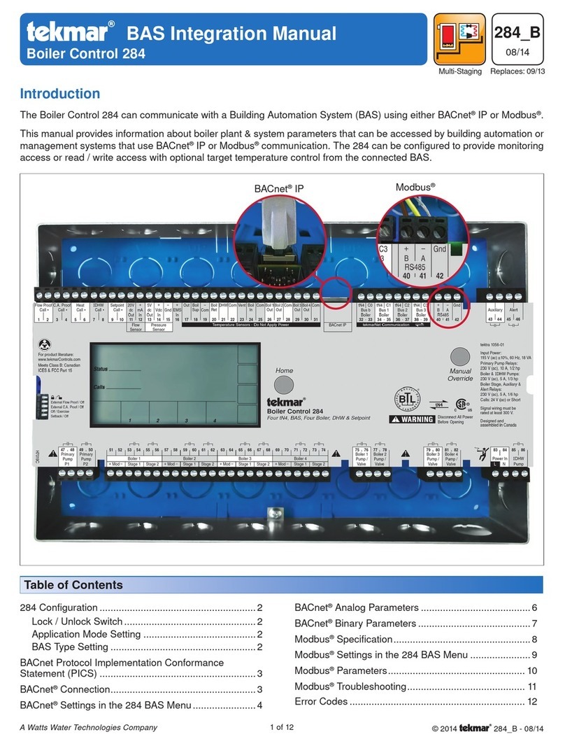
Other Tekmar Controllers manuals

Tekmar Snow Melting Control 680 Use and care manual

Tekmar

Tekmar Snow Melting Control 680 Use and care manual

Tekmar 155 User manual

Tekmar

Tekmar 155 User manual

Tekmar D 650 User manual

Tekmar

Tekmar D 650 User manual

Tekmar tekmarNet 4 Setpoint Control 161 User manual

Tekmar

Tekmar tekmarNet 4 Setpoint Control 161 User manual

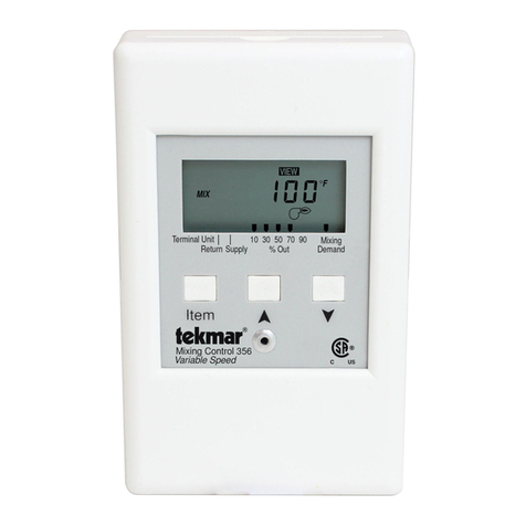
Tekmar Mixing Control 356 User manual

Tekmar

Tekmar Mixing Control 356 User manual

Tekmar tekmarNet 4 Setpoint Control 162 User manual

Tekmar

Tekmar tekmarNet 4 Setpoint Control 162 User manual

Tekmar 153 User manual

Tekmar

Tekmar 153 User manual

Tekmar 284 User manual

Tekmar

Tekmar 284 User manual

Tekmar 274 User manual

Tekmar

Tekmar 274 User manual

Tekmar 284 Use and care manual

Tekmar

Tekmar 284 Use and care manual

Tekmar House Control 401 User manual

Tekmar

Tekmar House Control 401 User manual

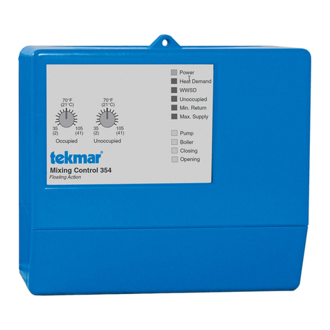
Tekmar Mixing Control 354 User manual

Tekmar

Tekmar Mixing Control 354 User manual

Popular Controllers manuals by other brands

PI M-227 Series user manual

PI

PI M-227 Series user manual

Mut meccanica tovo V200 Series manual

Mut meccanica tovo

Mut meccanica tovo V200 Series manual

Furrion FURRIONNET-ZERO FSCC30PW-BL instruction manual

Furrion

Furrion FURRIONNET-ZERO FSCC30PW-BL instruction manual

Sundaya Apple user manual

Sundaya

Sundaya Apple user manual

Moeller DEX-KEY-6 installation instructions

Moeller

Moeller DEX-KEY-6 installation instructions

Hunter 99111 Getting started

Hunter

Hunter 99111 Getting started

Fujitsu MB86617A Specification sheet

Fujitsu

Fujitsu MB86617A Specification sheet

Quickie VR2 user manual

Quickie

Quickie VR2 user manual

Altronix ACM4 Series installation guide

Altronix

Altronix ACM4 Series installation guide

Gardena C 2030 duo plus operating instructions

Gardena

Gardena C 2030 duo plus operating instructions

BFT ARES VELOCE SMART BT A500 NSTALLATION AND USER'S MANUAL

BFT

BFT ARES VELOCE SMART BT A500 NSTALLATION AND USER'S MANUAL

Anaheim Automation MDC300-240081 Series user guide

Anaheim Automation

Anaheim Automation MDC300-240081 Series user guide

AUMA SGM Series Operation instructions

AUMA

AUMA SGM Series Operation instructions

Vimar 03981 manual

Vimar

Vimar 03981 manual

Permobil PJSM user manual

Permobil

Permobil PJSM user manual

Nevco 805 Operator instructions

Nevco

Nevco 805 Operator instructions

Europa components ET1624PM operating instructions

Europa components

Europa components ET1624PM operating instructions

Moxa Technologies UC-7410 Quick installation guide

Moxa Technologies

Moxa Technologies UC-7410 Quick installation guide

manuals.online logo
manuals.online logoBrands
  • About & Mission
  • Contact us
  • Privacy Policy
  • Terms and Conditions

Copyright 2025 Manuals.Online. All Rights Reserved.