manuals.online logo
Brands
  1. Home
  2. •
  3. Brands
  4. •
  5. Precision matthews
  6. •
  7. Lathe
  8. •
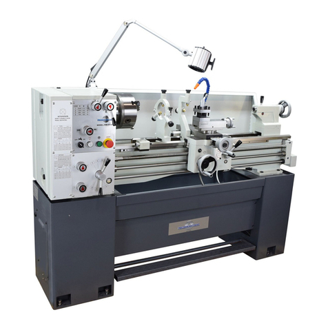
  9. Precision matthews PM-1440GS User manual

Precision matthews PM-1440GS User manual

Other Precision matthews Lathe manuals

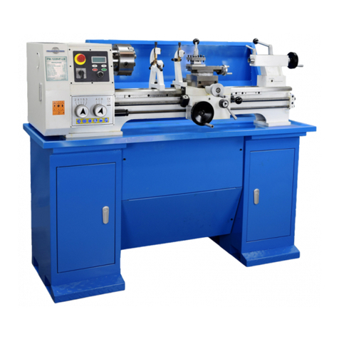
Precision matthews PM-1236T User manual

Precision matthews

Precision matthews PM-1236T User manual

Precision matthews PM-1127VF-LB User manual

Precision matthews

Precision matthews PM-1127VF-LB User manual

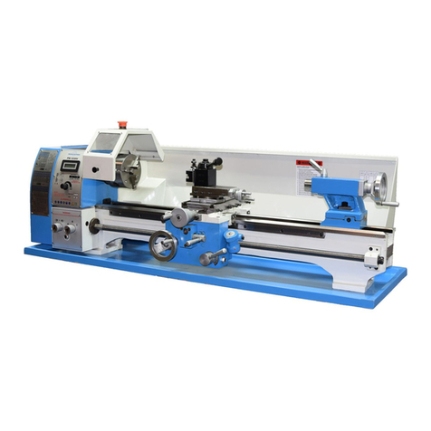
Precision matthews PM-1127VFI-LB Installation guide

Precision matthews

Precision matthews PM-1127VFI-LB Installation guide

Precision matthews PM-1022V User manual

Precision matthews

Precision matthews PM-1022V User manual

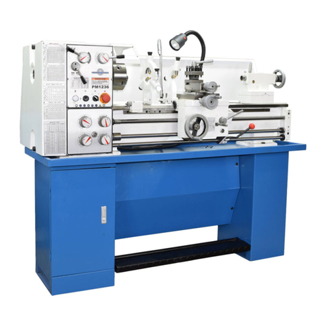
Precision matthews PM-1236 User manual

Precision matthews

Precision matthews PM-1236 User manual

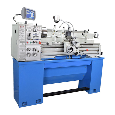
Precision matthews PM-1440BV User manual

Precision matthews

Precision matthews PM-1440BV User manual

Precision matthews PM-1440GT User manual

Precision matthews

Precision matthews PM-1440GT User manual

Precision matthews PM-1228VF-LB User manual

Precision matthews

Precision matthews PM-1228VF-LB User manual

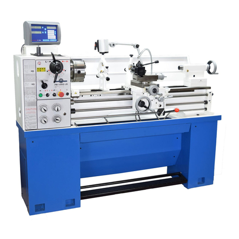
Precision matthews PM-1440E-LB Installation guide

Precision matthews

Precision matthews PM-1440E-LB Installation guide

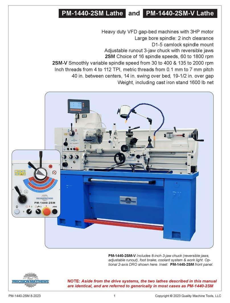
Precision matthews PM-1440-2SM User manual

Precision matthews

Precision matthews PM-1440-2SM User manual

Popular Lathe manuals by other brands

Jet JWL-1015 operating instructions

Jet

Jet JWL-1015 operating instructions

Holzmann VD 1100ECO user manual

Holzmann

Holzmann VD 1100ECO user manual

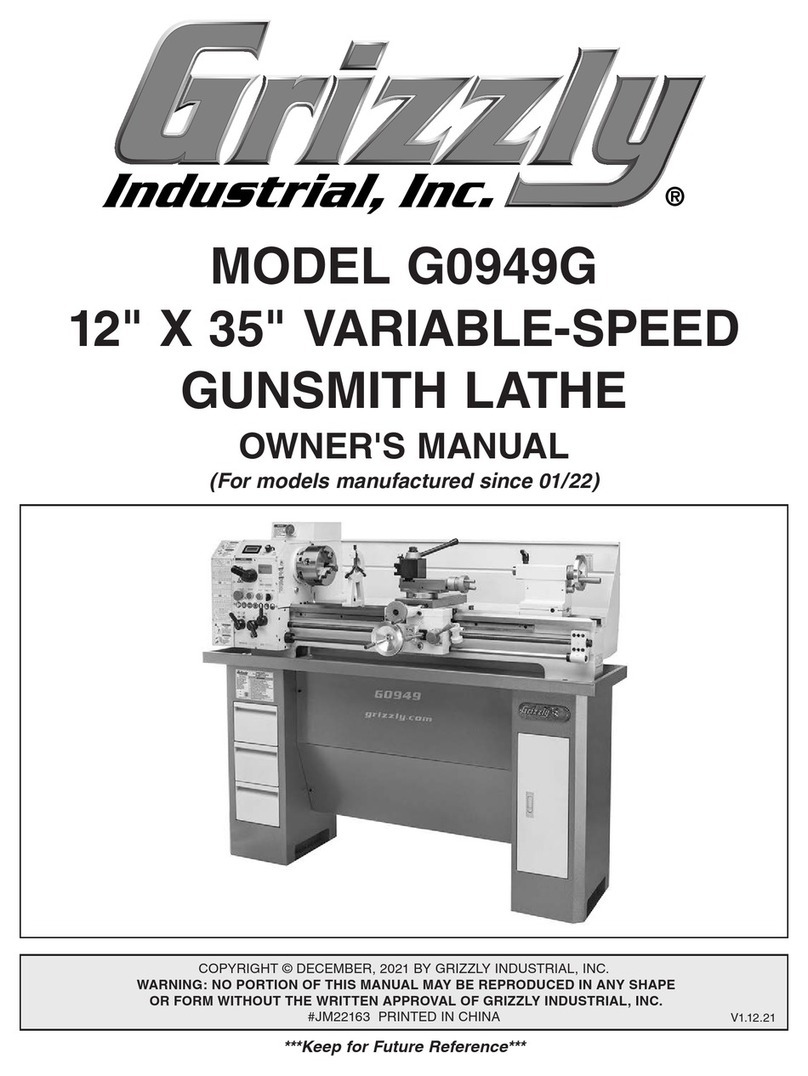
Grizzly G0949G owner's manual

Grizzly

Grizzly G0949G owner's manual

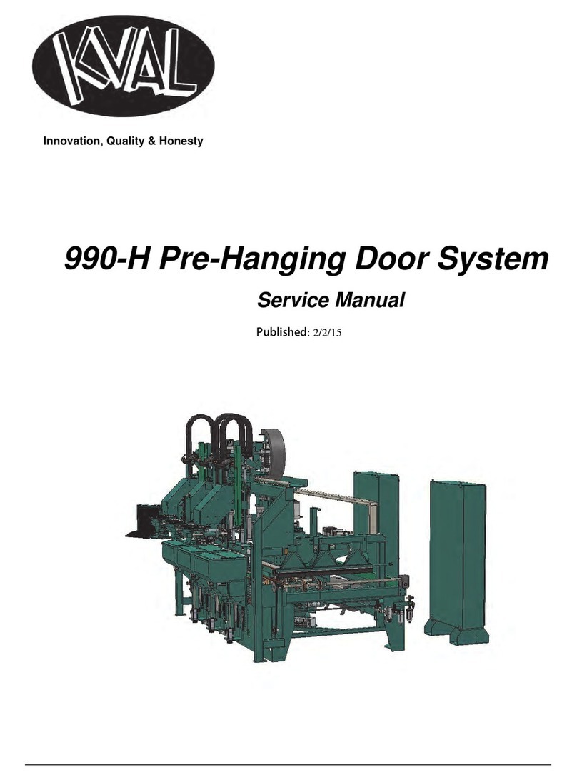
Kval 990-H Service manual

Kval

Kval 990-H Service manual

Grizzly G0632 Parts Breakdown

Grizzly

Grizzly G0632 Parts Breakdown

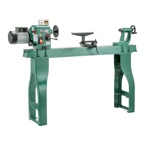
Grizzly G0462 owner's manual

Grizzly

Grizzly G0462 owner's manual

Teknatool Nova Mercury operating manual

Teknatool

Teknatool Nova Mercury operating manual

Milltronics ML Series Instruction handbook

Milltronics

Milltronics ML Series Instruction handbook

Milltronics SL6 Series Instruction handbook

Milltronics

Milltronics SL6 Series Instruction handbook

OmniTurn GT-75 user manual

OmniTurn

OmniTurn GT-75 user manual

Axminster CQ6230A-2/910 user manual

Axminster

Axminster CQ6230A-2/910 user manual

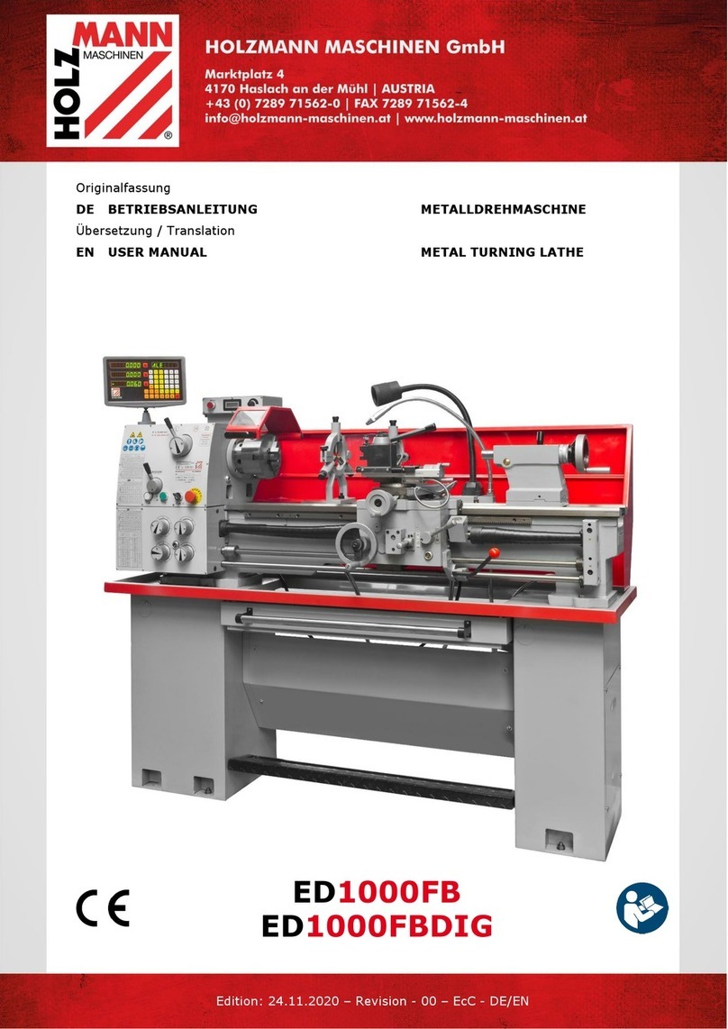
HOLZMANN MASCHINEN ED1000FB user manual

HOLZMANN MASCHINEN

HOLZMANN MASCHINEN ED1000FB user manual

Hercus 260 Maintenance manual

Hercus

Hercus 260 Maintenance manual

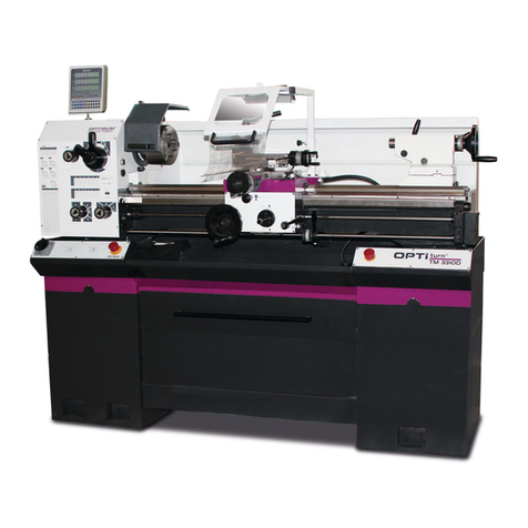
Optimum OPTIturn TM 3310 operating manual

Optimum

Optimum OPTIturn TM 3310 operating manual

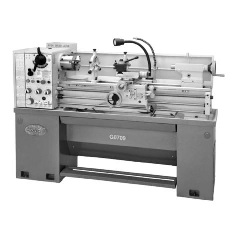
Grizzly G0709 owner's manual

Grizzly

Grizzly G0709 owner's manual

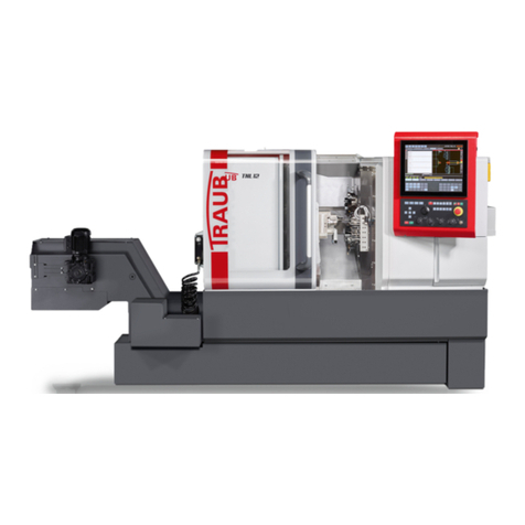
Traub TNL12.2 operating instructions

Traub

Traub TNL12.2 operating instructions

ELECTRABRAKE EB0625 instruction manual

ELECTRABRAKE

ELECTRABRAKE EB0625 instruction manual

AMMCO 3860 installation instructions

AMMCO

AMMCO 3860 installation instructions

manuals.online logo
manuals.online logoBrands
  • About & Mission
  • Contact us
  • Privacy Policy
  • Terms and Conditions

Copyright 2025 Manuals.Online. All Rights Reserved.

1Copyright © 2020 Quality Machine Tools, LLCPM-1440GS v3 2020-10
Model PM-1440GS Lathe
High precision 3 HP gap-bed machine, with 2-axis DRO
2 inch spindle bore, with stock-centering spider
D1-5 camlock spindle mount
40 in. between centers, 14 in. swing over bed, 19-3/4 in. over gap
8 spindle speeds from 60 to 1800 rpm
Multi-speed gearbox for full-range screw cutting, TPI & mm pitch
Bidirectional power feed for saddle & cross-slide
Weight, including cast iron stand & coolant system 1800 lb
PM-1440GS standard conguration Includes 2-axis DRO, 3-jaw (reversible) & 4-jaw chucks, faceplate,
coolant system, footbrake, worklight, steadies, wedge-type QC toolpost, assembled on cast iron stand
2Copyright © 2020 Quality Machine Tools, LLCPM-1440GS v3 2020-10
PM-1440GS
FAQ
POWER light o󰀨, left arrow?
240 Vac power connected?
Circuit breaker in the electrical box
tripped?
E-STOP button in, right arrow?
Rotate it, should pop out.
My lathe doesn’t
run at all (1)
This manual contains essential safety advice on the proper setup, operation, maintenance, and service of
the PM-1440GS lathe. Failure to read, understand and follow the manual may result in property damage
or serious personal injury.
There are many alternative ways to install and use a lathe. As the owner of the lathe you are solely
responsible for its proper installation and safe use. Consider the material contained in this manual to
be advisory only. Quality Machine Tools, LLC cannot be held liable for injury or property damage during
installation or use, or from negligence, improper training, machine modications or misuse.
This manual describes PM-1440GS machines as shipped from November 2016. There may be detail di󰀨erences between
your specic machine and the information given here (with little or no impact on functionality). Please email us if you have
questions about any aspect of the manual or your machine (see our website www.precisionmatthews.com for support
addresses). Your feedback is welcomed!
Belt cover in place? This closes the inter-
lock switch, bottom arrow.
FOOTBRAKE working, not stuck down?
If working properly, the footbrake should
close the microswitch, top arrow, opening
it when released.
CHUCK GUARD swung back? Close the
guard (photo, cover page).
The motor didn’t run when
power was connected
My lathe doesn’t
run at all (2)
By design it should NOT run if the Motor
Control lever is UP or DOWN when
power is connected.
Electrical schematic, Section 5: Move
the Motor Control switch to neutral, mid
travel, to energize the power-switching
contactor KA, thus restoring normal
conditions.
Copyright © 2020 Quality Machine Tools, LLC
This material was originated by Precision Matthews. No portion of
the manual may be reproduced or distributed in any form without
the written approval of Quality Machine Tools, LLC.
3Copyright © 2020 Quality Machine Tools, LLCPM-1440GS v3 2020-10
Section 1 INSTALLATION
THESE ARE THE MAIN POINTS TO WATCH OUT FOR!
But read the following pages for more information
• Handling the lathe is at least a two-man job.
• Lifting gear – sling, hoist or forklift – must be rated for at least 1-1/2 tons.
• Working location of the mill must allow space for removal of the belt cover at left; also, ac-
cess to the coolant system (back of right hand cabinet) and the electrical box at the back
of the headstock.
• Power requirement is 220V, 60Hz, 1φ, 20A circuit protection (spindle motor 12A full load).
• Extension cord not recommended; if no alternative, use 12 AWG not longer than 20 ft.
• Before connecting power be sure that:
1. The machine is on a rm footing.
2. Chuck camlocks tight, no wrench left in chuck.
3. Saddle and cross slide approx. mid-travel, power feed disengaged (Figure 1-9).
4. The headstock gear selectors are set for the lowest spindle speed.
SETTING UP THE LATHE
The PM-1440GS is shipped fully assembled in a single pack-
ing case. The machine can be lifted in one piece by an over-
head hoist or forklift with slings and/or chains, all items rated
for a total weight of at least 1-1/2 tons. To lift the machine clear
of the pallet use 1 inch diameter steel bars through the holes
in LH and RH stand cabinets, Figure 1-1.
Figure 1-1 Lifting holes
Install six 500 lb-rated leveling mounts in the mounting holes
of the two stand cabinets, 4 for the left hand cabinet, 2 for
the right. Alternatively, level the lathe using metal shims under
the cabinets. The mounts shown in Figure 1-2, available from
Precision Matthews, allow leveling adjustment from above.
To install this type of mount, remove the threaded stem from
the inverted cup stamping (yellow), then place the cup under
the stand with holes aligned — no washer between stand and
mount. If there is insu󰀩cient headroom in the stand, short-
en the threaded stem; re-install it, with washer and locknut,
through the hole in the stand. Once the stem has bottomed
in the mount, further rotation of the stem (using a wrench) ex-
pands the inner core of the mount, thus raising its upper sur-
face.
Inspect the coolant tank and pump assembly in the RH cabi-
net, Figure 1-3. The tank may have become dislodged in ship-
ment. Level it if necessary.
Figure 1-3 Coolant tank
Figure 1-2 Top-adjusting leveling mount (optional)
4Copyright © 2020 Quality Machine Tools, LLCPM-1440GS v3 2020-10
POWER CONNECTION
As shipped. the PM-1440GS is set for 220 V. If your supply is
nominally 240 V, it may be desirable to alter connections to the
24V transformer in the electrical box.
Read Initial Checks, next page, before connecting power
If the lathe did not come with a pre-installed power cord, con-
nect to the power source using 12 AWG (minimum) 3-wire cord
through a strain relief bushing sized for the electrical box ports.
Depending on installed options and other factors, the entry
point shown in Figure 1-6 may not be available. Connect the
ground wire (PE) to the grounding plate at bottom left. Connect
L1, L2 to the left-most two terminals on the bottom terminal
strip (the wires may be marked L, N instead of L1, L2).
Figure 1-5 Slide-out chip tray
Figure 1-4 Footbrake & belt cover interlocks
Brake OFF,
switch closed
Belt cover
switch
Foot treadle
operated,
(brake ON),
switch open
LEVELING
Make sure the lathe is in its permanent location. The following
procedure ensures that the lathe bed is in the same state as it
was when the lathe was checked for accuracy in manufacture
— level from end to end along the bed, and from front to back.
In other words, no warping.
Make sure all leveling mounts and/or shims are properly
weight bearing, rmly in contact with the oor. Check and ad-
just level from end to end using a precision machinist’s level, if
available. If not, use the most reliable level on hand. Check and
adjust level front-to-back across the bed using a matched pair
of spacer blocks to clear the Vee tenons on the bed ways. The
blocks need to be at least 1/4 inch thick, ground or otherwise
accurately dimensioned. Alternatively, check for level on the
ground surface of the cross slide as the carriage is traversed
from end to end. See also "Aligning the Lathe" in Section 4.
FOOTBRAKE & BELT COVER INTERLOCKS
The lathe will not run if the belt cover is removed, allowing the
interlock switch to open, Figure 1-4. The same applies if the
footbrake switch fails to close when the foot treadle is released
(brake OFF). Both switches should be checked before power
is connected.
Figure 1-6 Electrical box inputs/outputs
This conguration may vary depending on installed options, etc.
CLEANUP
Metal surfaces may have been protected by thick grease and/
or paper. Carefully remove these using a plastic paint scraper,
disposable rags and a light-oil such as WD-40.
CHIP TRAY
Check that the chip tray, Figure 1-5, can be pulled forward
without snagging coolant hoses and worklight wiring. Use ca-
ble ties if necessary.
5Copyright © 2020 Quality Machine Tools, LLCPM-1440GS v3 2020-10
INITIAL CHECKS
Read Section 3 if unsure about any item in the following
BEFORE connecting power, do the following:
1. Visually check the entire machine for possible distur-
bance in shipping, including the motor, Vee belts and
external gears under the belt cover left of the headstock.
Replace the belt cover.
2. Check oil level (sight glasses) in the headstock, the car-
riage feed gearbox, and the apron. See Section 4.
3. If a chuck or faceplate is installed, check tightness of the
six Camlocks on the spindle nose, Section 3.
4. Lower the chuck guard, photo on page 1.
5. Check the spider, left-hand end of the spindle. Locknuts
on the four clamp screws should be tight. Make sure that
the clamp screws clear the cover when the spindle is
rotated by hand
7. Set the H-L gear levers to the lowest spindle speed, 60
rpm. Make sure the gears are properly meshed by "jig-
gling while shifting" — rotate the chuck back and forth by
hand while moving the levers into position. Make certain
that the motor control lever is set to OFF, mid-travel,
Figure 1-7.
Figure 1-7 Motor control lever
Mid-travel OFF, DOWN Forward, UP Reverse
Figure 1-8 Front panel controls
8. Set the Saddle Feed Direction lever to its center (OFF)
position, Figure 1-8.
9. Check that there are no clamps or locks on moving parts.
10. Check that the footbrake treadle is released (UP).
11. Set the saddle and cross slide to approximate mid-travel.
12. Connect 220 Vac power. The power lamp, Figure 1-8,
should light, unless a circuit breaker in the electrical box
has tripped.
13. Be sure the Emergency Stop (E-Stop) button has not
been pushed in (it should pop out when twisted clock-
wise).
14. Shift the motor control lever DOWN. The spindle should
turn Forward, counter clockwise, viewed at the chuck
(nose) end. The control system can be rewired for
DOWN = Reverse, see the electrical diagram, Section 5.
15. Check the emergency function by pressing the E-Stop
button. The motor should stop. If this doesn’t happen,
the E-stop function is defective, and needs attention.
16. Reset (twist) the E-Stop button to restore power.
17. Check that the chuck guard switch stops the motor when
the guard is swung up.
18. Check that the belt cover interlock stops the motor when
the belt cover is removed.
19. Check that the footbrake stops the motor.
20. Return the motor control lever to OFF, mid-travel. The
motor should stop.
21. Shift the motor control lever UP. The spindle should
Reverse, clockwise rotation, viewed at the chuck (nose)
end. The control system can be rewired for UP = For-
ward, see the electrical diagram, Section 5.
Do not change speed when the motor is running.
6Copyright © 2020 Quality Machine Tools, LLCPM-1440GS v3 2020-10
OPTIONAL TEST RUN PROCEDURE
Run the spindle for a few minutes, forward and reverse, at a
selection of the available 8 speeds.
The carriage feed gearbox should also be run at this time, but
rst make certain that the leadscrew and feed shaft oilers at
the tailstock end have been lubricated.
Also note: In initial tests, because the saddle and cross slide
should rst be exercised manually, the leadscrew split-nut
should be disengaged — ditto the saddle/cross-slide power
feed lever, Figure 1-9. The power feed lever can be either in or
out, but it should be centered, neither up nor down.
ALIGNING THE LATHE
The most important attribute of a properly set up lathe is its
ability to “machine parallel”, to cut a cylinder of uniform diam-
eter over its entire length. In other words, no taper.
Leveling of the lathe is a part of this, see earlier in this section.
Equally important is the alignment of the center-to-center axis
with the lathe bed, as seen from above. [Vertical alignment is
nowhere near as critical, rarely causing taper unless the lathe
is damaged or badly worn.] For more information see the nal
pages of Section 4, Servicing the Lathe.
After the initial test run, perhaps with a few additional hours of
machine time, some users drain and rell the headstock and
carriage feed gearbox. Lubricants are specied in Section 4.
Other users prefer to delay this service action for at least 50
hours of running time. No specic recommendation is given by
Precision Matthews.
Figure 1-9 Feed control levers on apron
Saddle Power feed lever OUT & UP to engage. Cross-slide Lever IN
& DOWN to engage. Test for dis-engagement by turning the saddle
and cross-slide handwheels.
7Copyright © 2020 Quality Machine Tools, LLCPM-1440GS v3 2020-10
Section 2 FEATURES & SPECIFICATIONS
MODEL PM-1440GS Lathe
General information
This is a gap-bed lathe with 2-axis DRO designed for day-in, day-out use in the larger model shop. Distance be-
tween centers is 40in., swing over the bed 14 in. With an all-up weight of 1800 lb, plus 8 spindle speeds from 60
to 1800 rpm, the PM-1440GS is a robust heavy-duty machine. The spindle nose is D1-5 Camlock. A quick-change
carriage feed gearbox provides a full range of leadscrew ratios for U.S. and metric screw cutting, together with an
independent power feed for both saddle and cross slide. The power feed shaft is driven through a friction clutch
that allows the saddle to be stopped precisely at any point along the bed.
The 2-inch bore spindle comes with a stock-centering spider and MT6 internal taper. It runs on high-precision
NSK tapered-roller bearings, and is driven by a 3 HP (2200 W) 220 Vac single-phase motor. A treadle-operated
drum brake stops the spindle instantly, even at the highest speeds. A circulating coolant system is installed in the
right hand stand cabinet.
Accessories included
• 8 in. 3-jaw self centering chuck with two sets of jaws,
in-facing and out-facing
• 8 in. 4-jaw independent chuck with reversible jaws
• 200 Series precision wedge-type Quick Change
toolpost, with 5 toolholders
• Steady rest
• Follower rest
• Micrometer saddle stop
• Worklight
PM-1440GS Floor plan: dimensions approximate (not to scale)
8Copyright © 2020 Quality Machine Tools, LLCPM-1440GS v3 2020-10
PM-1440GS SPECIFICATIONS
Including stand: Width 71-1/2 in. x Height 51 in. x
Depth 31 in. (full range cross slide motion)
Footprint: 71-1/2 in. wide x 24 in. deep
Bed length 54 in.
Weight, approximate:1800 lb net
Power requirement
220 - 240Vac, 60 Hz, 1Ø, 12A full load
Motor TEFC type, cap start, 2.2 kW (3 HP), 1725 rpm
Work envelope
Center to center 40 in.
Spindle face to tailstock quill face 43-1/4 in.
Gap insert length 7-1/2 in.
Swing over gap 19-3/4 in. diameter
Swing over bed 14 in. diameter
Swing over cross slide 8-3/4 in. diameter
Saddle travel 38 in.
Cross-slide travel 7-3/4 in.
Compound (top slide) travel 3-3/4 in.
Drive system
(Belt drive with 8-speed gearbox)
Low range, rpm 60, 100, 170, 265
High range, rpm 420, 690, 1150, 1800
Carriage drive, thread cutting Leadscrew 8 tpi
Inch threads Choice of 42, from 4 to 112 TPI
Metric threads Choice of 44, from 0.1 mm to 7 mm pitch
Saddle drive, turning operations Choice of feed rates from 0.002 to 0.118 in./spindle rev
Cross slide drive, facing operations Choice of feed rates from 0.0005 to 0.03 in./spindle rev
Spindle
Chuck/faceplate attachment D1-5 Camlock
Internal taper MT6
Spindle bore Clearance for 2 in. diameter
Spindle length 17 in. overall
Tailstock
Internal taper MT4
Quill travel 4 in.
Work holding
3-jaw chuck, 8 in., self-centering (scroll) Reversible jaws
4-jaw chuck, 8 in., independent
Faceplate
Center rest (steady rest) capacity Up to 3 in. diameter
Follower rest capacity Up to 1 in. diameter
Dimensions, approximate overall, incl. stand
9Copyright © 2020 Quality Machine Tools, LLCPM-1440GS v3 2020-10
Everyday precautions
• This machine is intended for use by experienced users familiar with metal-
working hazards.
• Untrained or unsupervised operators risk serious injury.
• Wear ANSI-approved full-face or eye protection at all times when using the
machine (everyday eyeglasses are not reliable protection against ying par-
ticles).
• Wear proper apparel and non-slip footwear – be sure to prevent hair, clothing
or jewelry from becoming entangled in moving parts. Gloves – including tight-
tting disposables – can be hazardous!
• Be sure the work area is properly lit.
• Never leave chuck keys, wrenches or other loose tools on the machine.
• Be sure the workpiece, toolholder(s) and machine ways are secure before
commencing operations.
• Use moderation: light cuts, low spindle speeds and slow table motion give
better, safer results than “hogging”.
• Don’t try to stop a moving spindle by hand – allow it to stop on its own.
• Disconnect 220 Vac power from the lathe before maintenance operations
such as oiling or adjustments.
• Maintain the machine with care – check lubrication and adjustments daily
before use.
• Clean the machine routinely – remove chips by brush or vacuum, not com-
pressed air (which can force debris into the ways).
No list of precautions can cover everything.
You cannot be too careful!
10 Copyright © 2020 Quality Machine Tools, LLCPM-1440GS v3 2020-10
Section 3 USING THE LATHE
DRIVE TRAIN
Double-groove pulleys connect the motor to the gearbox, Fig-
ure 3-3. Belt tension will not usually require attention. If nec-
essary, loosen the three hex head bolts securing the motor,
Figure 3-4. Adjust the motor to re-tension. Make certain the
motor is properly aligned, then re-tighten the bolts.
What is not in this section ...
The PM-1440GS is a conventional engine lathe that requires
little explanation except for details specic to this particular
model — speed selection, thread cutting, and the saddle/
cross-slide power feed system. Because the user is assumed
to be familiar with general purpose metal lathes, this section
contains very little tutorial.
MOTOR CONTROLS Figure 3-1
Figure 3-1 Main control panel
Before doing ANYTHING, check the installation instruc-
tions and power-up procedure in Section 1
STOP the motor before changing speed
Don't use JOG unless the gears are fully meshed
Figure 3-3 Vee belts & external change gears
Firm nger
pressure here
should deect
the Vee belt
about 1/4"
JOG FEATURE
"Jog" is momentary-type push-button, active only if the Motor
Control lever is in the mid-travel (OFF) position, Figure 3-2.
Press the button briey to "nudge" the spindle in reverse by a
few degrees. Jog can be used to reposition the chuck and/or
workpiece, especially when low spindle-speed gearing makes
hand rotation di󰀩cult.
The control system can be rewired for "Forward Jog", see the
electrical diagram, Section 5.
Figure 3-2 Motor control lever
Mid-travel OFF, Down FORWARD, Up REVERSE
Before connecting power to the lathe, be sure the Motor Con-
trol Lever on the apron is set to OFF, Figure 3-2. Connect the
lathe to a 220 Vac outlet — the POWER lamp should light —
then operate the Motor Control Lever to run the spindle in the
desired direction.
Check that the following interlocks function correctly:
• E-Stop button
• Chuck guard
• Belt cover (to the left of the headstock)
• Footbrake