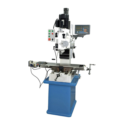
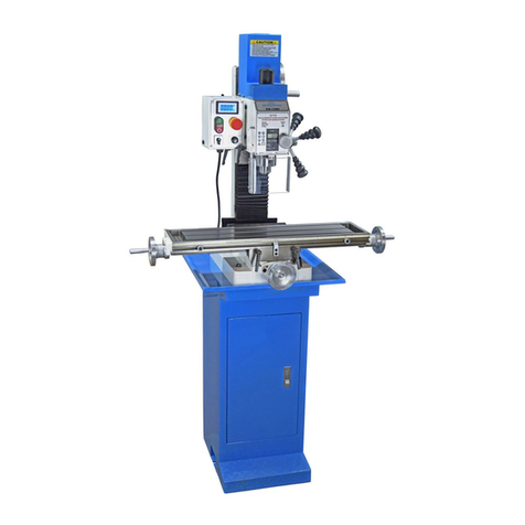
Precision matthews PM-932M User manual

1
932 Power downfeed option 4-16-18 V1 Copyright © 2018 Quality Machine Tools, LLC
Model PM-932M
PM-932M Mills with & without power downfeed option
Supplement to Section 2 of the PM-932M manual
QUILL DOWNFEED
Mills without power downfeed
The quill is controlled in two dierent ways, coarse and ne.
In the drilling mode, coarse feed, the mill functions like a
standard drill press – lower the quill using any of the three
downfeed levers to rotate the lever hub counter-clockwise. For
milling operations the lever hub is disengaged, and the quill is
controlled by the ne downfeed handwheel. The quill is locked
by a lever on the face of the headstock, Figure 2 (On power
downfeed versions of the PM-932 the quill locking lever is on
the left of the headstock, Figure 2 inset.)
Figure 1 Quill downfeed controls
The lever hub (1) is full-time connected to the quill pinion. The ne
control handwheel (2) is connected by a worm gear to the sleeve (3),
and is free to rotate — doing nothing to the quill — unless it is coupled
to the lever hub (1). Couple sleeve (3) to hub (1) by tightening knob (4).
Figure 2 DRO, depth stop & quill locking lever
Above, mills without power downfeed. On PM-932 mills with power
downfeed the quill locking lever is on the left side of the headstock,
inset.
Coarse feed (Figure 1)
For drilling operations, loosen knob (4), allowing the lever hub
to rotate independently of sleeve (3). If desired, set the depth
stop.
Fine feed (Figure 1)
For milling operations calling for precise, repeatable control
of tool depth, tighten knob (4) to engage the tapered face of
hub (1) with the internal taper on sleeve (3). Tighten the Z-axis
locks.
Rotate the ne control handwheel (2) to raise or lower the quill.
Before switching to ne control, it is usually a good idea to run
the depth stop up to the top. Lower the quill by rotating the ne
control knob clockwise, positioning it precisely either by count-
ing divisions on the graduated dial, or by reference to the front
panel DRO (digital readout). Use the locking lever to hold the
quill rmly in position.
If you are counting divisions be aware of backlash in the worm
drive. This means that the handwheel must always be turn-
ing in the same direction throughout the entire process, from
setting a reference level to subsequent cutting passes at spe-
cic depths – see the backlash discussion in Section 2 of the
manual. Using the DRO – which has no backlash issues – is
less laborious, but remember that the quill is spring-loaded.
This calls for care when releasing the quill locking lever prior
to repositioning the quill downward. If the ne control knob has
been allowed to disengage (backed o counter clockwise), the
quill will jump up by 0.01” or more. To avoid this, make sure
the ne control is rmly clockwise, lightly loading the quill rack,
before releasing the locking lever.
Depth stop adjust

2
932 Power downfeed option 4-16-18 V1 Copyright © 2018 Quality Machine Tools, LLC
QUILL DOWNFEED
Mills with power downfeed
This is a factory-installed option. Mills shipped
without this option cannot be retrotted.
Power downfeed can be used to reduce workload in many
routine operations including drilling, reaming, honing, and hole
boring with single point tools.
Three feed rates are available:
0.1 mm (~ 0.004”) per spindle revolution
0.18 mm (~ 0.007”)
0.26 mm (~ 0.010”)
The quill is controlled by hand in two dierent ways, coarse
and ne. The power downfeed system is described later in
this document.
In the drilling more (coarse feed) the mill functions like a stan-
dard drill press – pull the rearmost downfeed lever up and
over toward you to rotate the downfeed lever hub clockwise to
lower the quill. For milling operations the downfeed levers are
Figure 3 PM-932M mill with power downfeed option
right-shifted to engage the downfeed lever hub with the ne
control handwheel, which may then be rotated clockwise to
lower the quill under precise control.
Coarse feed (manual feed)
For drilling operations swing the downfeed levers inward — to-
ward the mill — to disengage the lever hub from the ne con-
trol handwheel. Tighten the downfeed lever stop screw to lock
the levers in position, thus preventing unintended engagement
of the power downfeed.
The graduated depth collar can be used to set a depth stop for
drilling as follows:
1. Tighten the Z-axis locks.
2. Lower the quill to bring the point of the drill down to the
desired end point, then tighten the quill locking lever.
3. Loosen the depth collar clamp lever to free the depth collar
Quill
downfeed
levers
Depth collar
clamp lever
Downfeed
lever stop
screw
Downfeed
lever hub
Depth
collar
Feed rate
selector
Power feed
engage/dis-
engage
Fine control
handwheel
Z-axis
lock
(1 of 2)

3
932 Power downfeed option 4-16-18 V1 Copyright © 2018 Quality Machine Tools, LLC
from the lever hub.
4. Rotate the depth collar clockwise as far as it will go (it
should indicate approximately 5 inches). When the depth
collar clamp lever is re-tightened, this will dene the quill’s
end stop.
5. Re-tighten the depth collar clamp lever.
6. Unlock the quill. While observing the DRO reading, raise
and lower the quill a few times to be sure the quill stops at
the desired end point.
Fine feed
For surfacing and other milling operations calling for precise
tool depth increments, use the ne control handwheel.
With the spindle stationary, set the Power Feed En-
gage and Feed Rate Selectors to OFF.
1. Tighten the Z-axis locks.
2. Loosen the downfeed lever stop screw to free the down-
feed levers.
3. Pivot the levers outward, testing for gear engagement as
you go (jiggle the levers as necessary to fully engage — no
gap between lever and its slot in the lever hub).
4. Lower the quill to the desired depth by rotating the ne
control handwheel clockwise (only).
5. Tighten the quill locking lever.
Note: Use the graduated dial on the ne control handwheel
for guidance only. It has 120 divisions of approximately 0.002”.
Use the DRO for precise downfeed control.
In Figure 4 a previously drilled hole is to be enlarged using a
single point boring tool. What follows is one of several possible
procedures.
1. With the quill fully retracted (1), lower the headstock to
bring the cutting tool just clear of the upper surface of the
workpiece.
2. Lock the Z-axis.
3. With the cutting tool inboard of the drilled hole, lower the
quill by hand to the desired end point for the tool (2).
4. Lock the quill, then set the depth collar to zero.
5. Tighten the depth collar clamp lever.
6. Release the quill locking lever, allowing the quill to retract
fully, position (1).
7. Is the SPINDLE STOPPED? Select a Feed Rate, then
set the Power Feed Engage knob to ON. Jiggle the spin-
dle and Fine Control by hand to ensure the power feed is
properly engaged.
8. Stay clear of the Fine Control knob — this will rotate
when the spindle runs.
9. Turn the spindle motor on, forward direction (F) only for
power feed.
10. Pivot the quill downfeed levers outward, feeling for gear
engagement as you go (jiggle the levers as necessary to
fully engage – no gap between lever and its slot in the
lever hub).
11. The quill will now descend under power until "0" on the
depth collar approaches the scale datum, at which point
the quill will retract rapidly to position (1) unless — recom-
mended — it is restrained by light pressure on the down-
feed levers.
Stop the spindle before touching the Power Feed En-
gage or Feed Rate Selector knobs
Key points to remember, referring to Figure 3:
• The Feed Rate selector knob can be turned either clockwise
or counter-clockwise to the OFF setting, but not beyond —
go back the other way instead.
• The graduated depth collar is free to rotate on the downfeed
lever hub only when the depth collar clamp lever is loose.
• When the depth collar clamp lever is tightened, the collar is
driven by the lever hub.
• The downfeed lever hub is full-time connected to the quill
pinion.
• Pivot the quill downfeed levers inward to control the quill by
hand, drill-press style.
• Pivot the levers outward to move the lever hub under pow-
er. Prevent premature disengagement by light outward
nger pressure on one of the levers.
• The lever hub automatically disengages from the power
feed — levers pivot inward — when the zero line (0) on
the depth collar nears the scale datum. At this point the
quill will reverse ABRUPTLY by spring action unless re-
strained by light nger pressure as noted above.
USING THE POWER DOWNFEED SYSTEM
Figure 4 Hole boring with power downfeed
Power downfeed example
Other manuals for PM-932M
1
Other Precision matthews Power Tools manuals

Precision matthews
Precision matthews PM-940M User manual

Precision matthews
Precision matthews PM-25MV User manual

Precision matthews
Precision matthews PM-833TV User manual

Precision matthews
Precision matthews PM 25MV-BD User manual

Precision matthews
Precision matthews PM 728V-T User manual

Precision matthews
Precision matthews PM-727M User manual

Precision matthews
Precision matthews PM-727M User manual

Precision matthews
Precision matthews PM-739M User manual

Precision matthews
Precision matthews PM-30MV User manual

Precision matthews
Precision matthews PM-932M User manual