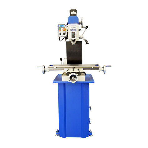
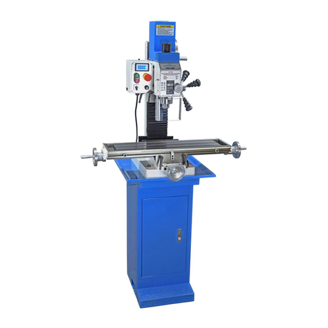
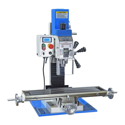
Precision matthews PM-739M User manual

PM-739M&V 2023-06 Copyright © 2023 Quality Machine Tools, LLC
1
Knee-mill features in a compact format: xed head height, adjustable table height
Choice of 6-speed gearbox PM-739M or variable-speed drive PM-739V
220V single phase supply, 2HP motor
Heavy HT200 cast-iron construction
Exceptional spindle height over table, 19-1/2” max
Quill DRO for precise downfeed measurement
Optional factory-installed 3-axis DRO
Weight, including cast iron stand 1100 lb net
PM-739 M-V Milling Machine
PM-739M
6-speed gearbox, 90 to
1970 rpm. Shown with
optional 3-axis DRO.
PM-739V
Variable-speed drive, 75
to 2500 rpm. Shown with
optional 3-axis DRO.

PM-739M&V 2023-06 Copyright © 2023 Quality Machine Tools, LLC
2
Unique features in a small knee mill ...
Unlike other small mills, the two PM-739 models have a vertically adjust-
able table supported by a knee casting that slides on precision-ground
dovetails — just like a conventional knee mill. Power-assist options are
available for table height and table X-axis (left-right motion).
The two PM-739 models oer the wide range of head ad-
justments shown above, typically available only on much
larger knee mills. These include full-circle rotatability, and
tilt motion in both the front-to-back (1) and left-to-right (2)
axes — very helpful when precise tramming is called for.
Fine adjustment of the forward tilt is facilitated by the worm
screw shown in (3) above.
1
2
Table crank handle
(height control)
Table leadscrew
Head
tilt ± 90o
Forward 30o
Back 15o
Head
swivels 360o
Forward
tilt adjust
3

PM-739M&V 2023-06 Copyright © 2023 Quality Machine Tools, LLC
3
PM-739M and PM-739V
FAQ
R8 devices won’t go
into the spindle
The collet locating screw
could be in too far. Remove
locking set screw, then back
the inner screw out a little.
My mill doesn’t run when I
press FORWARD OR RE-
VERSE
This manual contains essential safety advice on the proper setup, operation, maintenance, and ser-
vice of PM-739M and PM-739V milling machines. Failure to read, understand and follow the manual
may result in property damage or serious personal injury.
There are many alternative ways to install and use a mill. As the owner of the mill you are solely
responsible for its proper installation and safe use. Consider the material contained in this manual
to be advisory only. Quality Machine Tools, LLC cannot be held liable for injury or property damage
during installation or use, or from negligence, improper training, machine modications or misuse.
This manual describes machines shipped from early 2023. There may be detail dierences
between your specic machine and the information given here (with little or no impact on
functionality). Please email us if you have questions about any aspect of the manual or
your machine (see our website www.precisionmatthews.com for support addresses). Your
feedback is welcomed!
This material was originated by Precision Matthews. No portion of the manual may be repro-
duced or distributed in any form without the written approval of Quality Machine Tools, LLC.
Flange nut too far down
drawbar? Turn it count-
er-clockwise to touch the
drawbar nut.
Drawbar nut
Flange nut
220 Vac power connected?
739M POWER lamp lit?
739V Press the POWER push-button
E-STOP button pressed in? (pops out
when twisted clockwise)
739M Fuse FU1 good?—Section 4
739V Circuit breakers QF1, QF2
good?—Section 4
The drawbar doesn't
seem long enough
739M
739V

PM-739M&V 2023-06 Copyright © 2023 Quality Machine Tools, LLC
4
Section 1 FEATURES & SPECIFICATIONS
MODEL PM-739M and PM-739V Milling Machines
General information
These machines are exclusive to PM, and completely new to the market—compact as a bench-mill, but with knee-
mill features such as a vertically-adjustable table. Also, the headstock can be precisely tilted in two axes, side to
side and—uniquely—front-to-back, a capability that allows perfect alignment (tramming) of the spindle relative to
the table. The mills are designed for day-in, day-out use in model shop and light industrial applications. With a
weight of 1000 lbs plus they can handle far more than the typical machines of this size.
The two models of the 739 mills are identical in all respects other than their spindle drive trains. The 'M' version has
a 6-speed gearbox and 2HP single-speed motor, spindle speeds from 90 to 1970 rpm; the 'V' version has 2-speed
gearbox (HI/LO ranges) and a continuously variable speed 2HP motor, spindle speeds from 75 to 2500 rpm. In
both machines, the spindle runs in high quality (Class C5) tapered roller bearings enclosed in a heavy-duty quill
with coarse (drill-press style) and ne downfeed (worm drive) options. For precise control of cutter depth there is a
graduated dial and built-in DRO, completely independent of table elevation.
Precision ground dovetailed ways for horizontal and vertical motion of the table ensure smooth, precise motion in
all three axes: X = left/right motion of table 30 in., Y = front/back motion of table 8-1/2 in., Z = table up/down, 19-1/2
in. (Installation of DRO scales may limit these numbers.)
M: 82"
V: 84-3/4"
9" max
8-7/8"
Typical tilt range. Can be
tilted ± 90ofor handling
purposes.

PM-739M&V 2023-06 Copyright © 2023 Quality Machine Tools, LLC
5
PM-739M & PM-739V SPECIFICATIONS
Power requirement 220V, 60Hz single phase, 20A circuit
Approximate weight Net 830 lb, shipping 950 lb approx
General
Shipping container Height: 88" Width: 48" Depth: 42"
Machine height Normal operations, head untilted: 85 in.
Shipping cong, head tilted 90o: 72 in.
Floor space required
Width, over full left-right travel of table:
83 in.
Depth, Z-axis handle tip to back of chip
tray: 43 in.
Dimensions
Table
Table size 7-1/2 x 39 in.
Table height over oor 33-1/2 to 51 in.
Front-back travel, Y-axis With DRO 7-1/2 in. No DRO 8-1/2 in.
Left-right travel, X-axis With full way-support: 25 in.
Between hard stops: 30 in.
Vertical travel, Z-axis 19-1/2 in.
Leadscrew pitch, all axes 10 TPI (0.1 in. per turn)
Handwheel dials, all axes 0.001 in. graduations
T-slots Width: 14 mm (use PM 1/2 in. clamp kit)
Pitch: 50 mm
Motor & Headstock
Motor M: 2 HP single-phase ac V: 2HP three-
phase ac (from VFD)
Spindle speed PM-739M, two ranges LO range: 90, 210, 345
HI range: 670, 1180, 1970
Spindle speed PM-739V, two ranges Continuously variable, LO: 75 to 435 rpm
HI: 435 to 2500 rpm
Spindle dimensions
Internal taper: R8
Drawbar: 7/16-20, 19 mm wrench
Top end splines (6): 28 mm OD
Quill (spindle) travel 5 in.
Spindle nose to table 2 to 19-1/2 in.
Spindle nose to oor 53 in.
Spindle centerline to front face of column 8-7/8 in.
Headstock front to back tilt Back 30o , forward 15o
Headstock left to right tilt 90 degrees - zero - 90 degrees
T-slot dimensions

PM-739M&V 2023-06 Copyright © 2023 Quality Machine Tools, LLC
6
THESE ARE THE MAIN POINTS TO WATCH OUT FOR!
But read the following pages for more information
• Handling the mill is at least a two-man job.
• Lower the center of gravity by hand-cranking the knee (table support casting) down to
the fullest extent.
• Lifting gear – sling, hoist or forklift – must be rated for at least 1250 lb.
• The working location of the mill must allow full left-right travel of the table, also access to
the back of the column (electrical components).
• Power requirement is 220V, 60Hz, 1φ, 20A circuit protection
• Extension cord not recommended; if no alternative, use 12 AWG not longer than 20 ft.
• Before connecting power for the rst time be sure that:
1. The machine is on a rm footing, adequately secured to the oor.
2. No chuck or collet is installed.
3. There are no clamps or locks on moving parts.
Section 2 INSTALLATION
UNCRATING THE MILL
PM-739 mills are shipped fully assembled. Before mov-
ing the mill after dismantling the packing case, check
the mill's working location for head room, availability of
220 Vac, and condition of the oor — level, smooth and
weight-bearing capable. Check local codes for machine
tool fastening requirements. If none is specied, the mill
can be used free-standing, without anchors. If neces-
sary, install concrete anchors in the locations shown in
Figure 2-1.
MOVING THE MILL
This is at least a two-man procedure! First,
consider lowering the table and rotating the
head as shown on the next page.
Note that 1/2" screws are a snug t in the 4 holes in
the cast iron base — consider using 3/8" high tensile
screws instead. With oversize pockets in the concrete
oor there is no need for hole enlargement if the anchor
screws are pre-installed, and the mill is positioned be-
fore the embedding compound sets up.
When the mill is properly installed, the table should be
truly horizontal in both X and Y axes. To level the mill,
and to correct for irregularities in the concrete oor, use
metal shims positioned close to the anchor screws.
Figure 2-1B Floor drilling
Figure 2-1A Floor drilling
If available, use a forklift with a basket-style web sling to
lift and move the mill, Figure 2-2. Alternatively, a 1" di-
ameter steel rod can be inserted into the hole at the top
PM-739M&V 2023-06 Copyright © 2023 Quality Machine Tools, LLC
7
Figure 2-2 Forklift with web sling
of the column (labeled Hoisting Hole). This can be used
with two short slings as in Figure 2-3. A disadvantage
of this method is the serious backward tilt of the base
shown in Figure 2-3.
An engine hoist can be used instead of a forklift, but
this may require some experimentation. In the suggest-
ed procedure given here, the mill is lifted just enough to
allow the pallet to be removed. Thereafter the engine
hoist can be used to roll the mill.
Figure 2-3 Forklift with lifting rod
1. Set the upper arm of the hoist as far out as possible
— but not beyond the point where its lifting capacity
is less than 1250 lb.
2. Remove the screws securing the mill to the pallet.
3. At front and back edges of the pallet place 8" x 8"
or similar wood blocks to raise the hoist legs clear
of the pallet.
4. Position the hoist legs over the pallet so that the lift
chain is directly over the graduated tilt scale back of
the headstock, Figure 2-4. The casters should be
clear of the oor.
5. Run a short basket-style sling under the tilt scale,
wrapping the sling with soft material to prevent dam-
age to the paintwork and the scale. It may be desir-
able to remove the motor for better balance.
6. Slowly lift the mill, controlling any tendency for it to
swing as it clears the pallet.
7. Remove the pallet.
8. Lower the mill just clear of the oor, then roll it to its
working location.
Figure 2-4 Engine hoist

PM-739M&V 2023-06 Copyright © 2023 Quality Machine Tools, LLC
8
FINAL ASSEMBLY & CLEANUP
As shipped, the headstock is tilted for headroom in the
crate. Loosen the three nuts shown in 3-22, then rotate
the headstock for zero tilt by. Unnished metal surfac-
es are protected by thick grease and/or paper. Remove
these using a plastic paint scraper, disposable rags and
a light-oil type degreaser such as WD-40. Pump the one-
shot oiler 2 or 3 strokes to oil the ways (the leadscrews
are pre-greased). Check the sight glass for gearbox oil
level.
POWER FEED OPTIONS
Power-feed motors are available for both vertical and
left-right motion of the table. Both motors are powered
by 110 Vac. The motors in these units typically have twin
carbon brushes that should be inspected occasionally
and replaced if worn.
POWER-UP PROCEDURE
Before connecting power, follow items 1 through 7:
1. Press the STOP button, control panel bottom left,
Figure 2-5.
2. Pull out the E-STOP button.
3. Check that there are no clamps or locks on moving
parts.
4. The gearbox contains oil —check the sight glass at
right of the headstock.
5. Set the gear levers for lowest speed: M model—
select L-1; V model —select L, speed control fully
counter-clockwise.
6. Check that the gears are fully engaged – hand ro-
tate the spindle forward and back while applying
light pressure on each lever, listening for the click
as gears engage.
7. Depending on the available 220V outlet, install a
6-15 or 6-20 plug on the mill power cord. Be sure
the green/yellow ground wire is attached (it may be
tagged PE = Protective Earth).
Figure 2-5 Control panels: M model left, V model right

PM-739M&V 2023-06 Copyright © 2023 Quality Machine Tools, LLC
9
Section 3 USING THE MILL
Everyday precautions
●This machine is designed for milling and drilling operations by experienced
users familiar with metal-working hazards.
●Untrained or unsupervised operators risk serious injury.
●Wear ANSI-approved full-face or eye protection at all times when using the
machine (everyday eyeglasses are not reliable protection against ying particles).
●Wear proper apparel and non-slip footwear – be sure to prevent hair, clothing
or jewelry from becoming entangled in moving parts. Gloves – including tight-t-
ting disposables – can be hazardous!
●Be sure the work area is properly lit.
●Never leave chuck keys, wrenches or other loose tools on the machine.
●Be sure the workpiece and machine ways are secure before commencing mill-
ing or drilling – hold-downs and/or vise fully tightened, X-Y-Z axes locked, cutting
tool secured.
●Use moderation: light cuts, low spindle speeds and slow table motion give
better, safer results than “hogging”.
●Don’t try to stop a moving spindle by hand – allow it to stop on its own.
●Disconnect 220V power from the mill before maintenance operations such as
oiling or adjustments.
●Maintain the machine with care – check lubrication and adjustments daily
before use.
●Clean the machine routinely – remove chips by brush or vacuum, not com-
pressed air (which can force debris into the ways).
No list of precautions can cover everything.
You cannot be too careful!

PM-739M&V 2023-06 Copyright © 2023 Quality Machine Tools, LLC
10
Figure 3-1 PM-739M Controls
PM-739 M
Fine
downfeed
Motor controls
Down stop
adjust
Quill lock
Quill DRO
Hi / Lo
Range
select
Speed
select
Down
stop
1. Be sure the gearbox contains oil—sight glass at
right of headstock.
2. Check that there are no clamps or locks on moving
parts.
3. Pump the one-shot oiler a few times to lubricate the
sliding surfaces.
4. Set the gear levers for lowest speed, L-1.
5. Check that the gears are fully engaged—hand
First use ...
rotate the spindle forward and back while applying
light pressure on each lever, listening for the click as
gears engage.
6. Connect the mill to a 220Vac source. The POWER
lamp should light, indicating that power is available
to the motor control contactors. (If not, check that
the E-STOP button is not pushed in, and check
fuse FU1 in the motor control box, see the following
page).
7. Press either the FORWARD or REVERSE buttons
to run the spindle in the desired direction. Press the
STOP button to disconnect power from the spindle
motor. (The E-STOP button has the same eect as
the STOP button, but it should be used only for its
intended purpose—emergency disconnect.) The
E-STOP button is not momentary; once in, it stays in
until twisted clockwise.
L1 90
L2 210
L3 345
H1 670
H2 1180
H3 1970
Spindle
speeds
(rpm)
DO NOT SHIFT GEARS WHEN MOTOR
IS RUNNING. Allow the spindle to stop
completely before shifting gears.
●Before switching the spindle motor on, be sure that
the drive gears in the headstock are properly engaged.
●Hand-rotate (jiggle) the spindle forward and back
while applying light pressure on each gear-shift knob,
listening for the click as the gears engage.
Before doing anything, check the installation instructions in Section 2
Oiler

PM-739M&V 2023-06 Copyright © 2023 Quality Machine Tools, LLC
11
PM-739M WIRING DIAGRAM

PM-739M&V 2023-06 Copyright © 2023 Quality Machine Tools, LLC
12
PM-739 M
SCHEMATIC NOTES
KM1 and KM2 are line-powered (ac) contactors. They set
direction by swapping L and N lines to the motor.
When pushed, the E-STOP (SB1) button remains in, dis-
connecting power, until reset by twisting action.
STOP (SB2) is momentary-type switch: opens when pushed,
re-closes when released.
FORWARD & REVERSE (SB3 & SB4) are momentary type
push buttons that energize contactors KM1 and KM2 respec-
tively. The energized contactor forms a latching cir cuit that
continues to supply power to the motor when the push button
is released, and also positively ensures that for ward and
reverse directions cannot be selected at the same time.
Example: SB3 is pressed for forward motion, energizing
KM1, closing contacts KM1 to power the motor. At the same
time, another contact of KM1 creates a bypass line alongside
SB3 to hold KM1 in the energized state, thus maintaining
forward motion. A second contact of KM1 breaks the path to
contactor KM2, preventing an attempt to reverse the motor
through SB4 without rst stopping the motor (SB2).
Figure 3-3 PM-739M motor control box
Fuse FU1
FORWARD
CONTACTOR KM1
2A
Figure 3-2 PM-739M schematic
E-STOP
STOP
MOTOR
REVERSE
FOR-
WARD
WORK
LAMP
POWER
LAMP
REVERSE
CONTACTOR KM2
12
220 Vac

PM-739M&V 2023-06 Copyright © 2023 Quality Machine Tools, LLC
13
PM-739 M and V DRIVE TRAINS COMPARED
The PM-739M has a single-speed, single-phase 220V
motor, driving the spindle through a 6-speed gearbox,
Figure 3-4.
PM-739 M
Figure 3-4 PM-739M 6-speed gearbox
Figure 3-5 PM-739M Control panel underside
POWER
LAMP
FORWARDREVERSE
STOP
E-STOP
The 2-speed gearbox in the PM-739V is similar, except
that the 2-3-1 shifter is replaced by xed-speed inter-
mediate gears, Figure 3-8. The PM-739V 3-phase mo-
tor is powered by a Variable-Frequency Driver (VFD).

PM-739M&V 2023-06 Copyright © 2023 Quality Machine Tools, LLC
14
PM-739 V
Figure 3-6 PM-739V Controls
First use ...
1. Be sure the gearbox contains oil—sight glass at
right of headstock.
2. Check that there are no clamps or locks on moving
parts.
3. Pump the one-shot oiler a few times to lubricate
the sliding surfaces.
4. Set the range gear lever to L.
5. Turn the speed control, right of the display, fully
counter clockwise.
6. Check that the gears are fully engaged—hand
rotate the spindle forward and back while applying
light pressure on each lever, listening for the click
as gears engage.
7. Connect the mill to a 220Vac source.
8. Press the Power push button. The power lamp
should light, indicating that power is available to
the motor control contactors. (If not, check that the
E-STOP button is not pushed in, and check circuit
breakers QF1, QF2 (electrical compartment in back
of the column).
9. Press either the FORWARD or REVERSE buttons
to run the spindle in the desired direction. Adjust
the speed control as required.
10. Press the STOP button to disconnect power from
the spindle motor. (The E-STOP button has the
same eect as the STOP button, but it should be
used only for its intended purpose—emergency
disconnect. The E-STOP button is not momentary;
once in, it stays in until twisted clockwise.
DO NOT SHIFT GEARS WHEN MOTOR
IS RUNNING. Allow the spindle to stop
completely before changing range.
●Before switching on the spindle motor, be sure that
the drive gears in the headstock are properly engaged.
●Hand-rotate (jiggle) the spindle forward and back
while applying light pressure on Hi-Lo knob, listening
for the click as the gears engage.
Before doing anything, check the installation instructions in Section 2
Fine
downfeed
Motor controls
Down stop
adjust
Quill lock
Quill DRO
Hi / Lo
Range
select Down
stop
Spindle
speed
Speed
adjust
Oiler

PM-739M&V 2023-06 Copyright © 2023 Quality Machine Tools, LLC
15
PM-739V WIRING DIAGRAM

PM-739M&V 2023-06 Copyright © 2023 Quality Machine Tools, LLC
16
SCHEMATIC NOTES
KA, KM1 and KM2 are line-powered (ac) contactors. They
set spindle direction by swapping lines to the VFD.
When pushed, the E-STOP (SB1) button remains in, dis-
connecting power, until reset by twisting action.
When pushed, the POWER button (SB2) energizes contactor
KA. This supplies power via the normally-closed STOP push
button (SB3) to the FORWARD and REVERSE contactors
KM1 and KM2. At the same time, a contact of KA in parallel
with SB2 forms a latching circuit to maintain power when SB2
is released. ) is momentary-type switch: opens when pushed,
re-closes when released.
FORWARD (SB4) and REVERSE (SB5) are momentary type
push buttons that energize contactors KM1 and KM2 respec-
tively. The energized contactor forms a latching cir cuit that
continues to supply power to the motor when the push button
Figure 3-7 PM-739V schematic
Figure 3-8 PM-739V 2-speed gearbox
220 Vac
WORK
LAMP
POWER
LAMP
POWER
SWITCH
E-STOP
STOP
SPEED
SENSOR
SPEED
DISPLAY
CIRCUIT
BREAKER
CIRCUIT
BREAKER
24Vac
to 5Vdc
converter
12
FORWARD
CONTACTOR KM1
REVERSE
CONTACTOR KM2
To
DRO
To
POWER
FEEDS
FOR-
WARD
REVERSE
MOTOR FAN
KM2
KM2
KM2
KA
KM1
KM1
KA
KA
KM1
CONTACTOR
KA
PM-739 V

PM-739M&V 2023-06 Copyright © 2023 Quality Machine Tools, LLC
17
FORWARD
REVERSE
E-STOP STOP
POWER
SWITCH
SPEED
CONTROL SPEED
DISPLAY
SCHEMATIC NOTES (continued)
is released, and also positively ensures that for ward and
reverse directions cannot be selected at the same time.
Example: SB4 is pressed for forward motion, energizing
KM1, which powers the VFD. At the same time, a contact of
KM1 creates a bypass line—a latch—alongside SB4 to hold
KM1 in the energized state, thus maintaining forward mo-
tion. A second contact of KM1 breaks the path to contactor
KM2, preventing an attempt to reverse the motor through
SB5 without rst stopping the motor (SB3).
Figure 3-9 PM-739V Control panel underside
Figure 3-10 PM-739V Motor control compartment
PM-739 V

PM-739M&V 2023-06 Copyright © 2023 Quality Machine Tools, LLC
18
TOOLS REQUIRED
Two 3/4" or 19 mm wrenches are required to install or re-
move R8 tooling. It can sometimes be helpful to lock the
top end of the spindle with a 6-spline wrench (available
from most machinery distributors), Figure 3-14.
REMOVING R8 DEVICES
INSTALLING R8 DEVICES
1. Back out the ange nut on the drawbar to just touch-
ing the drawbar nut, Figure 3-12.
2. Install the R8 device, then hand-thread the drawbar
into it 6 or more full turns.
3. While holding the drawbar nut stationary, hand-
thread the ange nut down to touch the top of the
spindle.
4. Using one of the 3/4" wrenches, hold the drawbar
nut while fully tightening the ange nut using the
second 3/4" wrench.
Figure 3-14 Spindle wrench
Protect the table, vise or workpiece under
the spindle with rags or scrap wood. This
will prevent damage to—and by—falling tools
and drill chucks.
1. While holding the ange nut with the one of the 3/4"
wrenches, unscrew the drawbar with the second
wrench, one turn or less, just enough to unseat the
taper.
2. Tap the top of the drawbar with a brass or dead-
blow hammer to break the taper seal.
3. While supporting the R-8 device with the one hand,
fully unscrew and remove the drawbar with the other
hand.
PM-739 M and PM-739 V
DO NOT SHIFT GEARS WHEN MOTOR
IS RUNNING. Allow the spindle to stop
completely before shifting gears.
●Before switching on the spindle motor, be sure that
the drive gears in the headstock are properly engaged.
●Hand-rotate (jiggle) the spindle forward and back
while applying light pressure on each gear-shift knob,
listening for the click as the gears engage.
R8 DIFFICULTIES
R8 devices are located in the spindle bore by an M4 set
screw, which is locked by a second, outer, set screw. If it
is dicult or impossible to insert the R8 device, chances
are the inner set screw is in too far. Rotate the spindle by
hand to expose the screw, Figure 3-13, then use a ball-
end 2mm hex wrench to remove the outer screw. Back
out the inner screw a fraction of a turn, then re-lock with
the outer screw. Hand rotate the spindle again to check
that the screw clears the quill bore.
INSTALLING AND REMOVING TOOLING
The spindle and drawbar are designed for R-8 taper
collets, drill chucks and other arbors with the standard
7/16”-20 internal thread. R8 devices are secured in the
spindle by a drawbar, Figure 3-11.
Figure 3-11 Collet drawbar
Figure 3-13 Spindle set screw
7/16 - 20
Figure 3-12 Upper end of spindle
Drawbar nut
Flange nut

PM-739M&V 2023-06 Copyright © 2023 Quality Machine Tools, LLC
19
MOVING THE TABLE
Conventionally, left-right movement of the table is said
to be along the X-axis (also called “longitudinal travel” or
“traversing”). Leadscrew handles are provided at both
ends of the table, Figure 3-15. Front-to-back movement
is along the Y-axis, sometimes called “cross travel”. The
Y axis leadscrew has a single handle at the front, Figure
3-16.
Figure 3-16 Y-axis handle & dial
The thumbscrew (arrowed) locks the dial to
the leadscrew.
LOCKING THE AXES
Before machining a workpiece it is usually necessary to
position the table precisely. Using the lock levers, Figure
3-18, lock either the X or the Y axis, sometimes both, for
drilling and similar operations. You can also use the lock
levers to apply a light drag to the axis in motion. This
can help reduce chattering (better surface nish) and
also lessen the chance of overshooting inadvertently. To
reduce wear, free the levers once the operation is com-
pleted. The Z-axis can also be locked, but weight of the
table and knee assembly is usually enough to prevent
unwanted motion of the workpiece.
The X and Y axes both have graduated dials with 0.001"
divisions, 0.1" per revolution. If the mill is not equipped
with digital readouts (DROs), the table and headstock
can be accurately positioned by counting whole turns
and divisions, keeping leadscrew backlash in mind.
This means that motion must always be in the same
direction up to the point of reference, then on to the
desired location, see “Positioning by Counting X-Y Divi-
sions”, later in this section.
Figure 3-15 X-axis handle & dial (right hand)The
thumbscrew (arrowed) locks the dial to the leadscrew.
Y-axis handle
Z-axis crank
Vertical motion of the table is said to be in the Z-axis,
in line with the vertical column. The table is raised and
lowered by a crank handle that turns the vertical Z-axis
leadscrew, Figure 3-17. A spring-loaded dog clutch cou-
ples the crank handle to the elevation mechanism. Like
the X and Y axes, the Z axis has a graduated dial with
0.001" divisions, 0.1" per revolution.
Figure 3-17 Z-axis motion, table raised and lowered
The leadscrew nut is arrowed in the upper photo.
Z-axis crank
Figure 3-18 Axis locks
X
Y
Z
X

PM-739M&V 2023-06 Copyright © 2023 Quality Machine Tools, LLC
20
QUILL DOWNFEED
The quill is controlled in two dierent ways, coarse and
ne.
For drilling operations, coarse feed, the milling machine
operates like a standard drill press with a 3-lever hub.
Lever action lowers or raises the quill in the usual way
by rack and pinion.
For milling operations the lever hub is not usually ro-
tated by lever action. Instead it is driven through worm
gears turned by the ne control knob, Figures 3-19 (2)
and 3-20. This allows the quill to be driven precisely to
any desired position. The ne control knob, because it
drives through a worm, cannot be back-driven by quill
(in other words, it stays where it’s put). For milling oper-
ations the quill should, when possible, be fully retracted,
then locked by the lever on the front of the headstock,
Figures 3-1 and 3-6.
Coarse feed (Figure 3-19)
For drilling operations, loosen knob (4), allowing the le-
ver hub (1) to rotate independently of sleeve (3).
Fine feed (Figures 3-19, 3-20)
For milling operations calling for precise, repeatable
control of tool depth, tighten knob (4) to engage hub (1)
with the internal taper on sleeve (3).
Rotate the ne control knob (2) to raise or lower the quill.
Lower the quill by rotating the ne control knob clock-
wise, positioning it precisely either by counting divisions
on the graduated dial, or by reference to the quill digital
readout (DRO), Figures 3-1 and 3-6. Tighten the quill
lock to hold the quill rmly in position.
The quill DRO – which has no backlash issues – oers a
less laborious way of setting tool height, but bear in mind
that the quill is spring-loaded.
This calls for care when releasing the quill locking lever.
If the ne control knob has been allowed to disengage
(backed o counter clockwise), the quill may jump up by
0.01” or more. To avoid this, make sure the ne control
has been turned clockwise to apply downward pres-
sure on the quill before the locking lever is released.
If you are counting downfeed divisions be
aware of backlash in the worm drive.
QUILL DRO
The quill DRO is in metric mode when switched on. Press
the mm/in button to display inches.
Replace the battery by removing the small molded cover
on the face of the DRO unit (align the dots). Check the
type number and voltage of the installed battery. Replace
with an equivalent (LR44) silver oxide cell available from
local retailers.
Switch o the DRO when not in use!
Figure 3-20 Fine control handwheel
The thumbscrew (arrowed) locks the
dial to the handwheel spindle.
Figure 3-19 Quill downfeed controls
Lever hub (1) is keyed—connected full-time—to the pinion
shaft that drives the quill up and down. The ne control hand-
wheel (2) drives a worm gear on connector sleeve (3), which
rotates freely—doing nothing to the quill—until it is clamped to
the pinion shaft by knob (4).
When possible, operations calling for precise
depth control (such as milling) should be done
with the quill fully retracted into the headstock
and locked.
This manual suits for next models
1
Table of contents
Other Precision matthews Power Tools manuals

Precision matthews
Precision matthews PM-727M User manual

Precision matthews
Precision matthews PM-833TV User manual

Precision matthews
Precision matthews PM-940M User manual

Precision matthews
Precision matthews PM-932M User manual

Precision matthews
Precision matthews PM-835S User manual

Precision matthews
Precision matthews PM 25MV-BD User manual

Precision matthews
Precision matthews PM-727M User manual

Precision matthews
Precision matthews PM 728V-T User manual

Precision matthews
Precision matthews PM-932M User manual

Precision matthews
Precision matthews PM-25MV User manual