Precision Tech EndoGutta Pack User manual

EndoGuttaPack
Sistema per l’otturazione a caldo
Obturation Pack Handpiece
Manuale d’uso
User manual

2
Grazie per aver scelto Endo Gutta Pack Precision-Tech.
Tutti i prodotti a marchio Precision-Tech sono garantiti da Dentalica.
L’obiettivo di ogni dentista è prendersi cura dei suoi pazienti, il nostro è prenderci cura di ogni dentista.
Selezioniamo le migliori soluzioni, le testiamo, le facciamo nostre e le garantiamo con la nostra
esperienza prima e dopo l’acquisto.
Non esitare a contattarci per ulteriori informazioni circa il contenuto di questo manuale, se necessario:
Ti consigliamo di conservare il presente manuale per eventuali consultazioni future.
Il fabbricante si riserva il diritto di modicare le informazioni e i dati contenuti in questo manuale quando
necessario e senza l’obbligo di notica.
SIMBOLI UTILIZZATI SULLA CONFEZIONE, SUL DISPOSITIVO E SULLE SUE PARTI
Numero seriale Rappresentante Europeo
Codice Direttiva RAEE (Riuti di
Apparecchiature Elettriche ed
Elettroniche)
Fabbricante Conservare in luogo asciutto
Data di fabbricazione
55°C
-20°C
Temperatura di conservazione
Consultare il manuale d’uso
20%
80%
Umidità di conservazione
Direttiva Dispositivi Elettrici Medicali,
DS/EN 60601-1:2006, doppio
isolamento elettrico, Classe II 70kPa
106kPa
Pressione atmosferica di conservazione
Direttiva Dispositivi Elettrici Medicali,
DS/EN 60601-1:2006
Protezione shock elettrici, parte
applicata di tipo B
Corrente diretta
Direttiva Dispositivi Medici, MDD
93/42/EEC, Dispositivo Medico Classe I
SIMBOLI UTILIZZATI NELLE ISTRUZIONI PER L’USO
Avvertenza
Se le istruzioni non vengono adeguatamente seguite, l’operazione può comportare rischi
per il prodotto, il dentista o il paziente.
Nota
Informazioni aggiuntive, spiegazione di operazioni e prestazioni.

3
Endo Gutta Pack
Sistema per l’otturazione a caldo
INDICE
1. Scopo di Endo Gutta Pack
1.1. Identicazione graca dei componenti
1.2. Componenti
1.3. Accessori (venduti separatamente)
2. Prima dell’uso
2.1. Destinazione d’uso
2.2. Controindicazioni
3. Installazione di Endo Gutta Pack
3.1. Installazione del plugger
3.2. Installazione dell’alimentatore
3.3. Collegamento della base di ricarica
4. Interfaccia di utilizzo
5. Impostazioni
5.1. Impostazione della memoria
5.2. Impostazioni avanzate
6. Funzionalità
6.1. Ricarica
6.2. Riscaldamento
7. Manutenzione
8. Risoluzione dei problemi
9. Dati tecnici
10. Tabelle EMC
11. Dichiarazione
...........................................pag. 4
...........................................pag. 4
...........................................pag. 5
...........................................pag. 5
...........................................pag. 5
...........................................pag. 5
...........................................pag. 5
...........................................pag. 6
...........................................pag. 6
...........................................pag. 7
...........................................pag. 7
...........................................pag. 8
...........................................pag. 9
...........................................pag. 9
...........................................pag. 9
...........................................pag. 10
...........................................pag. 10
...........................................pag. 10
...........................................pag. 11
...........................................pag. 13
...........................................pag. 13
...........................................pag. 14
...........................................pag. 16

4
1. SCOPO DI ENDO GUTTA PACK
1.1 Identicazione graca dei componenti
1 Scope of Fast-Pack
1. Scope of Fast-Pack
1.1 Parts Identification
1
2
3
4
1.Charge Base
2.Handpiece
3.Heating Needle(3PCS)
4.Adapter
Page 4 / 26
1. Base di ricarica
2. Manipolo
3. Plugger (3 pezzi)
4. Alimentatore

5
1.2 Componenti
MANIPOLO ENDO GUTTA PACK
(1 PEZZO) BASE DI RICARICA
(1 PEZZO)
ALIMENTATORE
(1 PEZZO)
1 Scope of Fast-Pack
1.2 Components and Accessories
Fast-Pack Handpiece (1pcs)
Part No. 6351001
Charge Base (1pcs)
Part No. 6351003
Adapter (1pcs)
Part No. 6316001+ 6316005
Heating needle S (1pcs)
Size: 40/0.025
Color: Black
Part No. 6351006
Heating needle M (1pcs)
Size: 50/0.05
Color: Yellow
Part No. 6351007
Heating needle L (1pcs)
Size: 60/0.06
Color: Blue
Part No. 6351008
1.3 Options (sold separately)
Handpiece Base
Part No. 6005002
Page 5 / 26
PR00ENDOGPB
PLUGGER, MISURA S
(1 PEZZO) PLUGGER, MISURA M
(1 PEZZO)
PLUGGER, MISURA L
(1 PEZZO)
Dimensione: 40/0.025
Colore: Nero
Dimensione: 50/0.05
Colore: Giallo
Dimensione: 60/0.06
Colore: Blu
1 Scope of Fast-Pack
1.2 Components and Accessories
Fast-Pack Handpiece (1pcs)
Part No. 6351001
Charge Base (1pcs)
Part No. 6351003
Adapter (1pcs)
Part No. 6316001+ 6316005
Heating needle S (1pcs)
Size: 40/0.025
Color: Black
Part No. 6351006
Heating needle M (1pcs)
Size: 50/0.05
Color: Yellow
Part No. 6351007
Heating needle L (1pcs)
Size: 60/0.06
Color: Blue
Part No. 6351008
1.3 Options (sold separately)
Handpiece Base
Part No. 6005002
Page 5 / 26
PR00ENDOGPS PR00ENDOGPM PR00ENDOGPL
1.3 Accessori (venduti separatamente)
SUPPORTO MANIPOLO
1 Scope of Fast-Pack
1.2 Components and Accessories
Fast-Pack Handpiece (1pcs)
Part No. 6351001
Charge Base (1pcs)
Part No. 6351003
Adapter (1pcs)
Part No. 6316001+ 6316005
Heating needle S (1pcs)
Size: 40/0.025
Color: Black
Part No. 6351006
Heating needle M (1pcs)
Size: 50/0.05
Color: Yellow
Part No. 6351007
Heating needle L (1pcs)
Size: 60/0.06
Color: Blue
Part No. 6351008
1.3 Options (sold separately)
Handpiece Base
Part No. 6005002
Page 5 / 26
PR00ENDOGPZ
2. PRIMA DELL’USO
2.1 Destinazione d’uso
Endo Gutta Pack è destinato al riscaldamento e al taglio della guttaperca durante il trattamento del canale
radicolare.
Questo dispositivo deve essere utilizzato solo in ambienti ospedalieri, cliniche o studi dentistici da perso-
nale odontoiatrico qualicato.
2.2 Controindicazioni
Questo dispositivo non deve essere utilizzato nel caso in cui il paziente sia portatore di pacemaker car-
diaco impiantato (o altre apparecchiature elettriche) ed è stato messo in guardia contro l’uso di piccoli
elettrodomestici (come rasoi elettrici, asciugacapelli, ecc.).
La sicurezza e l’efcacia non sono state dimostrate su donne in gravidanza e bambini.

6
Avvertenze
Leggere le seguenti avvertenze prima dell’uso:
• Non utilizzare questo dispositivo per procedure differenti dall’otturazione canalare.
• Non utilizzare il dispositivo in presenza di alte concentrazioni d’ossigeno, miscele di gas
anestetici inammabili o sostanze inammabili.
• Il dispositivo non deve essere riposto in ambienti umidi o dovunque possa essere a contatto
con liquidi.
• Esiste un rischio di pericolo per il paziente a causa delle temperature elevate che può
raggiungere lo strumento.
• Non esporre il dispositivo a fonti di calore dirette o indirette. Il dispositivo deve essere
utilizzato e riposto in un ambiente sicuro.
• Il dispositivo richiede speciali precauzioni rispetto alla compatibilità elettromagnetica
(EMC) e deve essere installato e utilizzato in concordanza con queste informazioni. In
particolare, non utilizzare il dispositivo vicino a fonti di luce uorescente, trasmettitori
radio, apparecchi di controllo remoto, dispositivi di comunicazione RF portatili o mobili
e non ricarica, utilizzare o riporre ad alte temperature. È necessario attenersi alle condi-
zioni di utilizzo e stoccaggio sovra specicate.
• Utilizzare sempre guanti e diga in gomma durante il trattamento.
• Se si manifestano irregolarità del dispositivo durante il funzionamento, spegnere im-
mediatamente e contattare il distributore.
• Non aprire o riparare il dispositivo da soli, pena l’eliminazione della garanzia.
3. INSTALLAZIONE DI ENDO GUTTA PACK
3.1 Installazione del plugger
4Installing the Fast-Pack
4.1 Installation of heating
needle
Make sure the inner hexagon notch on
heating needle is aligned with the outer
hexagon boss on handpiece, push till
to position.
Holding the grey shell to pull the
heating needle out from the handpiece.
The heating needle can be installed in
any one of 6 orientations.Pull it out
from handpiece then can be installed in
other orientations.
WARNIN G
To remove the heating needle, wait
for it to cool down, it takes about 2-3
seconds, and real-time temperature
will show on the screen.
Even the heating needle cool down
already, we strongly recommend not
touch the metal part on heating
needle, there is a risk of heat injure
or damage the heating needle, hold
the grey shell to remove.
4.2 Installation of adapter
Plug the head into the base if they are
separated in the package.
Page 9 / 26
4Installing the Fast-Pack
4.1 Installation of heating
needle
Make sure the inner hexagon notch on
heating needle is aligned with the outer
hexagon boss on handpiece, push till
to position.
Holding the grey shell to pull the
heating needle out from the handpiece.
The heating needle can be installed in
any one of 6 orientations.Pull it out
from handpiece then can be installed in
other orientations.
WARNING
To remove the heating needle, wait
for it to cool down, it takes about 2-3
seconds, and real-time temperature
will show on the screen.
Even the heating needle cool down
already, we strongly recommend not
touch the metal part on heating
needle, there is a risk of heat injure
or damage the heating needle, hold
the grey shell to remove.
4.2 Installation of adapter
Plug the head into the base if they are
separated in the package.
Page 9 / 26
1. Assicurarsi che la tacca esagonale interna sul
plugger sia allineata con la sporgenza esagonale
esterna sul manipolo, spingere no al posizio-
namento.
2. Estrarre il plugger dal manipolo afferrandolo
tramite l’anello grigio.
4Installing the Fast-Pack
4.1 Installation of heating
needle
Make sure the inner hexagon notch on
heating needle is aligned with the outer
hexagon boss on handpiece, push till
to position.
Holding the grey shell to pull the
heating needle out from the handpiece.
The heating needle can be installed in
any one of 6 orientations.Pull it out
from handpiece then can be installed in
other orientations.
WARNING
To remove the heating needle, wait
for it to cool down, it takes about 2-3
seconds, and real-time temperature
will show on the screen.
Even the heating needle cool down
already, we strongly recommend not
touch the metal part on heating
needle, there is a risk of heat injure
or damage the heating needle, hold
the grey shell to remove.
4.2 Installation of adapter
Plug the head into the base if they are
separated in the package.
Page 9 / 26
3. Il plugger può essere inserito in una delle sei
differenti posizioni.

7
Avvertenze
•Per rimuovere il plugger, attendere che si raf-
freddi, dopo circa 2-3 secondi la temperatura
apparirà sullo schermo in tempo reale.
• Quando il plugger si sta raffreddando, si consi-
glia vivamente di non toccare la parte metalli-
ca, per evitare lesioni termiche o danni all’ago.
4Installing the Fast-Pack
4.1 Installation of
heating
needle
Make sure the inner hexagon notch on
heating needle is aligned with the outer
hexagon boss on
handpiece, push till
to position.
Holding the grey shell
to pull the
heating needle out from the handpiece.
The heating needle can be installed in
any one of 6 orientations.
Pull it out
from handpiece then can be installed in
other orientations.
WARNING
To remove the heating needle, wait
for it to cool down, it takes about 2-3
seconds, and real-time temperature
will show on the screen.
Even the heating needle cool down
already, we strongly recommend not
touch the metal part on heating
needle, there is a risk of heat injure
or damage the heating needle, hold
the grey shell to remove.
4.2 Installation of adapter
Plug the head into the base if they are
separated in the package.
Page 9 / 26
3.2 Installazione dell’alimentatore
Se sono separati nella confezione, inserire la testa
nella base.
4Installing the Fast-Pack
4.1 Installation of
heating
needle
Make sure the inner hexagon notch on
heating needle is aligned with the outer
hexagon boss on
handpiece, push till
to position.
Holding the grey shell
to pull the
heating needle out from the handpiece.
The heating needle can be installed in
any one of 6 orientations.
Pull it out
from handpiece then can be installed in
other orientations.
WARNING
To remove the heating needle, wait
for it to cool down, it takes about 2-3
seconds, and real-time temperature
will show on the screen.
Even the heating needle cool down
already, we strongly recommend not
touch the metal part on heating
needle, there is a risk of heat injure
or damage the heating needle, hold
the grey shell to remove.
4.2 Installation of adapter
Plug the head into the base if they are
separated in the package.
Page 9 / 26
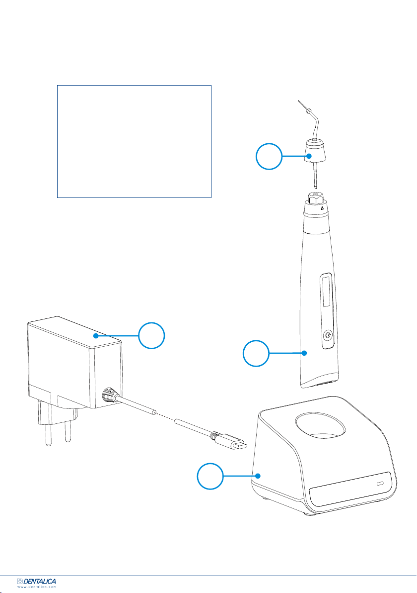
3.3 Collegamento della base di ricarica
4 Installing the Fast-Pack
4.3 Connecting charge base
Plug the USB of adapter into the
charge base, and plug the other end
into a power outlet.
The Power LED on charge base will
light up.
NOTE
Only the original adapter could be
used.
Put the handpiece all the way into the
charge base, the charge state will show
on the screen.
NOTE
Put the handpiece into the charge base
in the right direction, otherwise the
handpiece will not be charged.
If only need a base to put the device on
dentist element of dental chair (without
charge function), handpiece base is
recommended to use instead of charge
base.
Power LED
Page 10 / 26
1. Inserire la presa USB dell’alimentatore nella base di
ricarica e inserire l’altra estremità nella presa elettrica.
2. La luce sulla base di ricarica di accenderà.
Attenzione: possono essere utilizzati solo alimentatori originali.
4 Installing the Fast-Pack
4.3 Connecting charge base
Plug the USB of adapter into the
charge base, and plug the other end
into a power outlet.
The Power LED on charge base will
light up.
NOTE
Only the original adapter could be
used.
Put the handpiece all the way into the
charge base, the charge state will show
on the screen.
NOTE
Put the handpiece into the charge base
in the right direction, otherwise the
handpiece will not be charged.
If only need a base to put the device on
dentist element of dental chair (without
charge function), handpiece base is
recommended to use instead of charge
base.
Power LED
Page 10 / 26
3. Posizionare il manipolo nella base di ricarica, lo
stato di carica verrà visualizzato sullo schermo.
8
Attenzione
• Porre il manipolo all’interno della base di ricarica
nella direzione corretta, altrimenti, lo strumento
non si ricaricherà.
4 Installing the Fast-Pack
4.3 Connecting charge base
Plug the USB of adapter into the
charge base, and plug the other end
into a power outlet.
The Power LED on charge base will
light up.
NOT E
Only the original adapter could be
used.
Put the handpiece all the way into the
charge base, the charge state will show
on the screen.
NOT E
Put the handpiece into the charge base
in the right direction, otherwise the
handpiece will not be charged.
If only need a base to put the device on
dentist element of dental chair (without
charge function), handpiece base is
recommended to use instead of charge
base.
Power LED
Page 10 / 26
4 Installing the Fast-Pack
4.3 Connecting charge base
Plug the USB of adapter into the
charge base, and plug the other end
into a power outlet.
The Power LED on charge base will
light up.
NOTE
Only the original adapter could be
used.
Put the handpiece all the way into the
charge base, the charge state will show
on the screen.
NOTE
Put the handpiece into the charge base
in the right direction, otherwise the
handpiece will not be charged.
If only need a base to put the device on
dentist element of dental chair (without
charge function), handpiece base is
recommended to use instead of charge
base.
Power LED
Page 10 / 26
4. Se è necessaria una base per posizionare il
dispositivo sul portatray della poltrona odonto-
iatrica (senza funzione di ricarica), si consiglia
di utilizzare il supporto per il manipolo al posto
della base di ricarica.
4. INTERFACCIA DI UTILIZZO
5 Use Interface
5.Use Interface
1
2
3
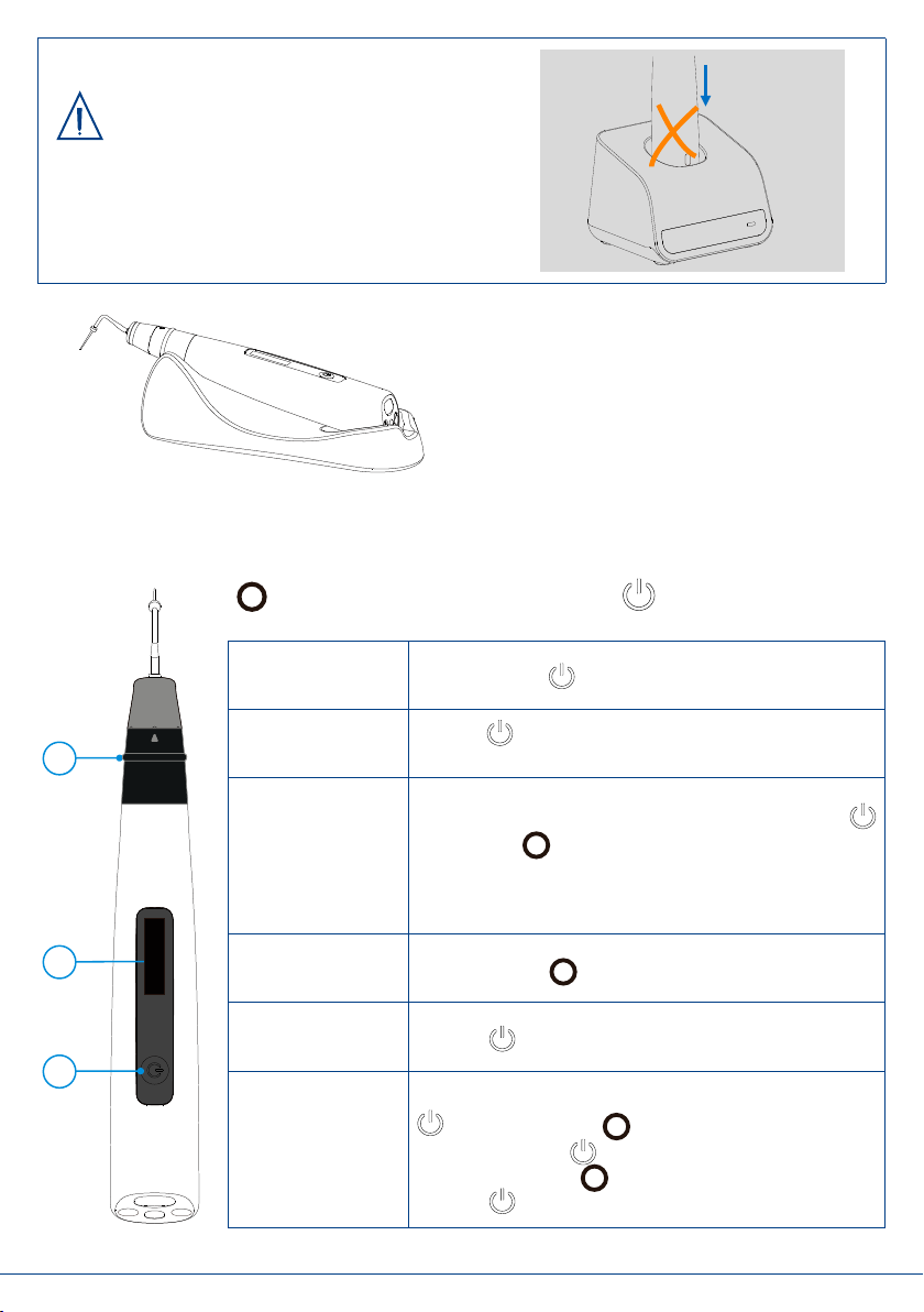
①Main switch
②Display Screen
③Power switch
Turn Power On
Long press
Change Memory
Shot press to change temperature memory
from T1 to T5
Memory Parameter Setting
During standby state, holding down press
then press in 2 seconds to entry memory
parameter setting, parameter of T1 to T5 can be
set independently
Heating
Long press
Turn Power Off
Long press more than 2 seconds
Advanced setting
During power off state, holding down press
then press to entry advanced setting, Press
till target setting, press to adjust, then
press to confirm
Page 11 / 26
1. Pulsante principale 2. Display 3. Pulsante d’accensione
ACCENSIONE Tenere premuto .
CAMBIO DI
MODALITÀ
Premere per cambiare la temperatura memorizzata da
T1 a T5.
REGOLAZIONE
DEI PARAMETRI
Durante la fase di standby, tenere premuto il pulsante
poi premere per due secondi per accedere alla
sezione di regolazione dei parametri, i parametri da T1 a
T5 possono essere impostati in maniera indipendente.
RISCALDAMENTO Tenere premuto .
SPEGNIMENTO Premere per più di due secondi.
IMPOSTAZIONI
AVANZATE
Quando lo strumento è spento, tenere premuto il pulsante
e successivamente per entrare nelle impostazioni
avanzate. Premere per scegliere il parametro da
impostare, premere per aggiustare il parametro, poi
premere per confermare.
9
5. IMPOSTAZIONI
5.1 Impostazione della memoria
6 Setting
6.Setting
6.1 Memory Parameter Setting
Fast-Pack has 5 memory programs, press to
change during standby state, the memory number
T1 will change according.
During any Memory, holding down press then
press in 2 seconds, the “Temperature” of this
memory can be change.
Press till target temperature, the temperature
can be set from 90℃to 250℃.
press to confirm.
Press again, the “Keep-heat Time” of this
memory can be change.
Press till target time, the time can be set 3, 5, 8
and 10 seconds.
press to confirm.
Press again, the “CoolingDisplay” of this
memory can be change.
Press till target time, the time can be set 0, 3, 5
and 10 seconds.
press to confirm.
Page 12 / 26
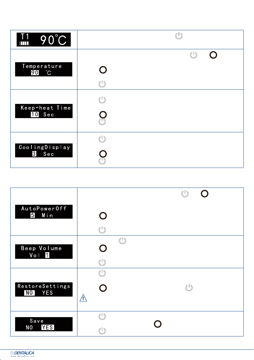
Endo Gutta Pack ha 5 programmi, premere per cambiare programma
durante lo stato di standby, il programma T1 cambierà.
6 Setting
6.Setting
6.1 Memory Parameter Setting
Fast-Pack has 5 memory programs, press to
change during standby state, the memory number
T1 will change according.
During any Memory, holding down press then
press in 2 seconds, the “Temperature” of this
memory can be change.
Press till target temperature, the temperature
can be set from 90℃to 250℃.
press to confirm.
Press again, the “Keep-heat Time” of this
memory can be change.
Press till target time, the time can be set 3, 5, 8
and 10 seconds.
press to confirm.
Press again, the “CoolingDisplay” of this
memory can be change.
Press till target time, the time can be set 0, 3, 5
and 10 seconds.
press to confirm.
Page 12 / 26
Una volta selezionato il programma, tener premuto , poi per due
secondi, per poter cambiare la temperatura del programma.
Premere no alla temperatura desiderata, il range di temperatura sele-
zionabile è compreso tra 90°C e 250°C.
Premere per confermare la temperatura desiderata.
6 Setting
6.Setting
6.1 Memory Parameter Setting
Fast-Pack has 5 memory programs, press to
change during standby state, the memory number
T1 will change according.
During any Memory, holding down press then
press in 2 seconds, the “Temperature” of this
memory can be change.
Press till target temperature, the temperature
can be set from 90℃to 250℃.
press to confirm.
Press again, the “Keep-heat Time” of this
memory can be change.
Press till target time, the time can be set 3, 5, 8
and 10 seconds.
press to confirm.
Press again, the “CoolingDisplay” of this
memory can be change.
Press till target time, the time can be set 0, 3, 5
and 10 seconds.
press to confirm.
Page 12 / 26
Premere di nuovo per poter modicare il tempo di riscaldamento
(“Keep-heatTime”) del programma selezionato.
Premere no al tempo desiderato, che può essere di 3, 5, 8 e 10 s.
Premere per confermare.
6 Setting
6.Setting
6.1 Memory Parameter Setting
Fast-Pack has 5 memory programs, press to
change during standby state, the memory number
T1 will change according.
During any Memory, holding down press then
press in 2 seconds, the “Temperature” of this
memory can be change.
Press till target temperature, the temperature
can be set from 90℃to 250℃.
press to confirm.
Press again, the “Keep-heat Time” of this
memory can be change.
Press till target time, the time can be set 3, 5, 8
and 10 seconds.
press to confirm.
Press again, the “CoolingDisplay” of this
memory can be change.
Press till target time, the time can be set 0, 3, 5
and 10 seconds.
press to confirm.
Page 12 / 26
Premere di nuovo per poter modicare il tempo di raffreddamento
(“CoolingDisplay”) del programma selezionato.
Premere no al tempo desiderato, che può essere di 3, 5, 8 e 10 s.
Premere per confermare.
5.2 Impostazioni avanzate
6 Setting
6.2 Advanced Setting
During power off state, holding down press
then press to entry advanced setting, the
“AutoPowerOff” will appear on the display screen.
Press to adjust, the auto power off time can be
set 5, 10 and 15 minutes
press to confirm.
Press again, the “Beep Volume” can be
change, press to adjust, the “Beep Volume”
can be set 0, 1 and 2.
press to confirm.
Press again, the “RestoreSettings” can be
change, press to adjust, press to confirm.
NOTE
If choice “YES”, all the setting parameters will be
covered by factory settings.
Press again, confirm the setting need to save
or not, press to adjust, press to save and
power off.
Page 13 / 26
Quando lo strumento è spento, tenere premuto , poi per due
secondi, per accedere alla sezione dedicata alle impostazioni avanzate, la
dicitura “AutoPowerOff” apparirà sullo schermo.
Premere per selezionare il tempo di spegnimento automatico desidera-
to, è possibile scegliere tra le opzioni 5, 10 e 15 minuti.
Premere per confermare.
6 Setting
6.2 Advanced Setting
During power off state, holding down press
then press to entry advanced setting, the
“AutoPowerOff” will appear on the display screen.
Press to adjust, the auto power off time can be
set 5, 10 and 15 minutes
press to confirm.
Press again, the “Beep Volume” can be
change, press to adjust, the “Beep Volume”
can be set 0, 1 and 2.
press to confirm.
Press again, the “RestoreSettings” can be
change, press to adjust, press to confirm.
NOTE
If choice “YES”, all the setting parameters will be
covered by factory settings.
Press again, confirm the setting need to save
or not, press to adjust, press to save and
power off.
Page 13 / 26
Premere di nuovo per poter cambiare il volume (“BeepVolume”).
Premere per selezionare quello desiderato, è possibile scegliere tra
l’opzione 0, 1 e 2.
Premere per confermare.
6 Setting
6.2 Advanced Setting
During power off state, holding down press
then press to entry advanced setting, the
“AutoPowerOff” will appear on the display screen.
Press to adjust, the auto power off time can be
set 5, 10 and 15 minutes
press to confirm.
Press again, the “Beep Volume” can be
change, press to adjust, the “Beep Volume”
can be set 0, 1 and 2.
press to confirm.
Press again, the “RestoreSettings” can be
change, press to adjust, press to confirm.
NOTE
If choice “YES”, all the setting parameters will be
covered by factory settings.
Press again, confirm the setting need to save
or not, press to adjust, press to save and
power off.
Page 13 / 26
Premere di nuovo per poter settare lo strumento con le impostazioni di
fabbricazione “RestoreSetting”.
Premere per selezionareYES o NO. Premere per confermare.
Nota: se viene selezionato “YES”, verranno reimpostati i parametri di
fabbricazione.
6 Setting
6.2 Advanced Setting
During power off state, holding down press
then press to entry advanced setting, the
“AutoPowerOff” will appear on the display screen.
Press to adjust, the auto power off time can be
set 5, 10 and 15 minutes
press to confirm.
Press again, the “Beep Volume” can be
change, press to adjust, the “Beep Volume”
can be set 0, 1 and 2.
press to confirm.
Press again, the “RestoreSettings” can be
change, press to adjust, press to confirm.
NOTE
If choice “YES”, all the setting parameters will be
covered by factory settings.
Press again, confirm the setting need to save
or not, press to adjust, press to save and
power off.
Page 13 / 26
Premere di nuovo per poter confermare se le impostazioni devono
essere salvate oppure no, premere per selezionareYES o NO.
Premere per confermare.

10
6. FUNZIONALITÀ
6.1 Ricarica
7 Operation
7.Operation
7.1 Charge
Displays the present remaining amount of the
battery.
Less than 15% remains, please charge.
NOTE
If the power if less than 15%, must be recharged
within 30 days, otherwise the battery will be
damaged.
Charge without charge base also available, using
adapter connect to handpiece directly, the charge
state will show on the screen.
Charge with charge base is recommended (See
chapter 4.3 Connecting charge base 错误!未找到
引用源。).
NOTE
Only the original adapter could be used.
Charging indication appears on the screen, and
flashes slowly, when battery is fully charged or in a
state near full charge, the flash will stop. Fully
charged will take about 4 hours, depending on
residual battery power and battery state.
It can be recharged 300-500 times, depending on
the operating conditions of the device.
WARNIN G
Do not change the battery, only trained technician
or distributor can change the battery, the electronic
parts will be damaged if use a wrong battery or
install with a wrong way.
Page 14 / 26
L’immagine mostra la percentuale di batteria rimanente.
Se è inferiore al 15%, si prega di ricaricare lo strumento.
Nota
Se è presente una percentuale di batteria inferiore al 15%, lo strumento
deve essere ricaricato entro 30 giorni, altrimenti la batteria potrebbe
danneggiarsi.
7 Operation
7.Operation
7.1 Charge
Displays the present remaining amount of the
battery.
Less than 15% remains, please charge.
NOTE
If the power if less than 15%, must be recharged
within 30 days, otherwise the battery will be
damaged.
Charge without charge base also available, using
adapter connect to handpiece directly, the charge
state will show on the screen.
Charge with charge base is recommended (See
chapter 4.3 Connecting charge base 错误!未找到
引用源。).
NOTE
Only the original adapter could be used.
Charging indication appears on the screen, and
flashes slowly, when battery is fully charged or in a
state near full charge, the flash will stop. Fully
charged will take about 4 hours, depending on
residual battery power and battery state.
It can be recharged 300-500 times, depending on
the operating conditions of the device.
WARNIN G
Do not change the battery, only trained technician
or distributor can change the battery, the electronic
parts will be damaged if use a wrong battery or
install with a wrong way.
Page 14 / 26
È possibile ricaricare lo strumento anche senza l’utilizzo della base di
ricarica, collegando l’alimentatore direttamente al manipolo, lo stato di
carica verrà mostrato sul display. In ogni caso, è raccomandata la rica-
rica dello strumento utilizzando la base di ricarica (vedi paragrafo 3.3
Collegamento della base di ricarica).
Nota
Può essere utilizzato solo l’alimentatore originale.
7 Operation
7.Operation
7.1 Charge
Displays the present remaining amount of the
battery.
Less than 15% remains, please charge.
NOTE
If the power if less than 15%, must be recharged
within 30 days, otherwise the battery will be
damaged.
Charge without charge base also available, using
adapter connect to handpiece directly, the charge
state will show on the screen.
Charge with charge base is recommended (See
chapter 4.3 Connecting charge base 错误!未找到
引用源。).
NOTE
Only the original adapter could be used.
Charging indication appears on the screen, and
flashes slowly, when battery is fully charged or in a
state near full charge, the flash will stop. Fully
charged will take about 4 hours, depending on
residual battery power and battery state.
It can be recharged 300-500 times, depending on
the operating conditions of the device.
WARNIN G
Do not change the battery, only trained technician
or distributor can change the battery, the electronic
parts will be damaged if use a wrong battery or
install with a wrong way.
Page 14 / 26
L’indicazione di ricarica appare sullo schermo e lampeggia lentamente;
quando la batteria è carica al 100% o vicino a questo valore, lo schermo
smette di lampeggiare.
Una ricarica completa richiede circa 4 ore, in base alla percentuale di
carica residua e allo stato della batteria.
Lo strumento può essere ricaricato 300-500 volte, a seconda delle opera-
zioni operative dello strumento.
Avvertenze
Non cambiare la batteria, afdarsi al distributore. Le parti elettroniche
potrebbero danneggiarsi se viene utilizzata una batteria errata o se viene
installata in modo errato.
6.2 Riscaldamento
7 Operation
Press and hold the raised ridge on the
ring switch to heat the heating needle.
The indicator LED lights up during
heating.
Only the end of heating needle (about 4-
5mm) will be heated, use this area to cut
the gutta percha.
1
The “Keep-heat Time” will display
on screen, When the set time is reached,
heating process will switch off.
2
Heating indication
3
Real time heating temperature
Page 15 / 26
Tenere premuto l’anello rialzato sull’interruttore ad anello per riscaldare
il plugger.
7 Operation
Press and hold the raised ridge on the
ring switch to heat the heating needle.
The indicator LED lights up during
heating.
Only the end of heating needle (about 4-
5mm) will be heated, use this area to cut
the gutta percha.
1
The “Keep-heat Time” will display
on screen, When the set time is reached,
heating process will switch off.
2
Heating indication
3
Real time heating temperature
Page 15 / 26
Il LED si accenderà durante il riscaldamento.
Modalità di caricamento
alternativa
11
7 Operation
Press and hold the raised ridge on the
ring switch to heat the heating needle.
The indicator LED lights up during
heating.
Only the end of heating needle (about 4-
5mm) will be heated, use this area to cut
the gutta percha.
1
The “Keep-heat Time” will display
on screen, When the set time is reached,
heating process will switch off.
2
Heating indication
3
Real time heating temperature
Page 15 / 26
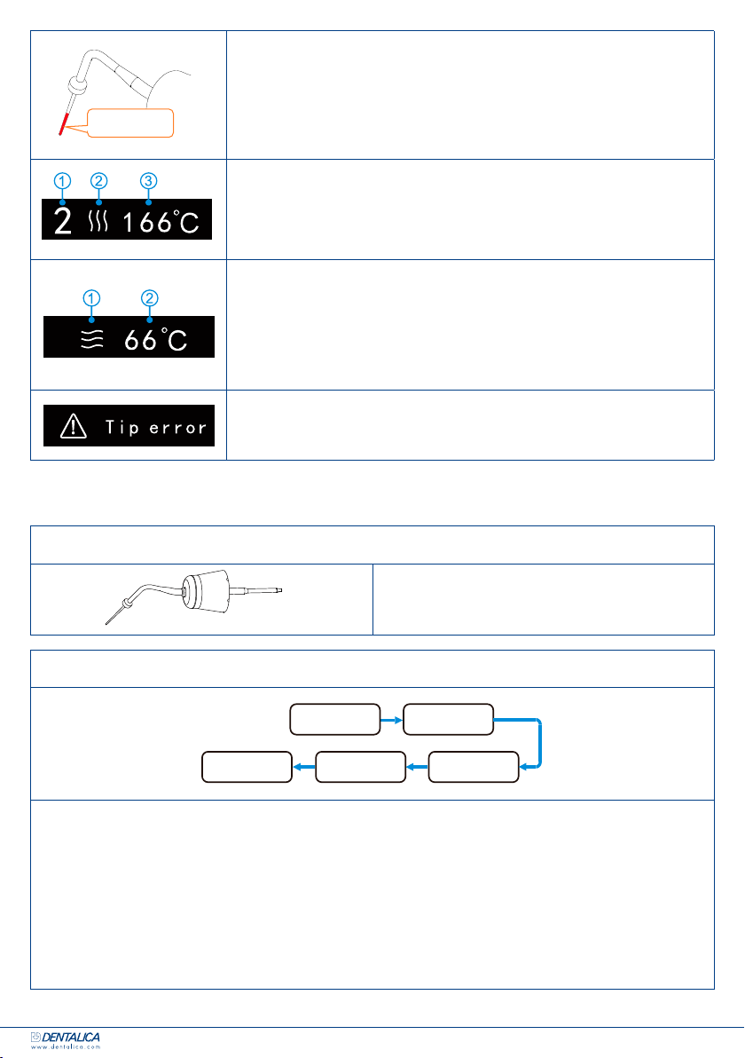
Solo la parte nale del plugger (circa 4-5 mm) si riscalderà, utilizza
quest’area per tagliare la gutta percha.
7 Operation
Press and hold the raised ridge on the
ring switch to heat the heating needle.
The indicator LED lights up during
heating.
Only the end of heating needle (about 4-
5mm) will be heated, use this area to cut
the gutta percha.
1
The “Keep-heat Time” will display
on screen, When the set time is reached,
heating process will switch off.
2
Heating indication
3
Real time heating temperature
Page 15 / 26
1. Il tempo di riscaldamento viene mostrato sul display, quando il tempo
selezionato viene raggiunto, il processo di riscaldamento si interrompe.
2. Indicazione di riscaldamento.
3. Temperatura di riscaldamento in tempo reale.
7 Operation
Release your finger from the ring switch,
the heating needle will be cooling.
1
the cooling indication will appear.
2
Real time temperature of cooling
heating needle will appear.
When the set time of “CoolingDisplay” is
reached, will change to standby
interface.
If the heating needle isn’t installed
properly, or the heating needle broken,
the “Tip error” will appear.
Page 16 / 26
Togliendo il dito dall’interruttore ad anello, il plugger inizierà a raffreddar-
si.
1. L’indicazione di raffreddamento apparirà.
2. La temperatura di raffreddamento del plugger apparirà in tempo reale
sul display. Quando il tempo di raffreddamento (“Cooling Display”)
viene raggiunto, il dispositivo va in standby.
7 Operation
Release your finger from the ring switch,
the heating needle will be cooling.
1
the cooling indication will appear.
2
Real time temperature of cooling
heating needle will appear.
When the set time of “CoolingDisplay” is
reached, will change to standby
interface.
If the heating needle isn’t installed
properly, or the heating needle broken,
the “Tip error” will appear.
Page 16 / 26
Se l’ago riscaldante non è inserito correttamente o è rotto, apparirà la
dicitura “Tip Error” “errore di puntale”.
7. MANUTENZIONE
COMPONENTI AUTOCLAVABILI
8Maintenance
8.Maintenance
Autoclavable Components
Heating needle
Autoclavable Procedure
Cleaning: Cleanthe components with running water with a soft cloth.
Disinfection: Wipe the components with a piece of gauze that has been
dampened with Ethanol for Disinfection (Ethanol 70 to 80 vol%) and wrung out
thoroughly.
Packing: Pack the components in“Sterilization pouches”.
Sterilization: Steam sterilization at 134°C at least 6 minutes,
Minimum drying time after sterilization: 10 minutes.
Storage: Keep the components in sterilization packaging in a dry and clean
environment.
WARNING
Comply with your national guidelines, standards and requirements for cleaning,
disinfection and sterilization.
Be careful to avoid cross contamination when performing maintenance.
Must be autoclaved after use for each.
Only heating needle can be autoclavable.
NOTE
Heating needle head is easy to damage by external force, take care during
maintenance.
Page 17 / 26
PLUGGER
PROCEDURA DI STERILIZZAZIONE IN AUTOCLAVE
8Maintenance
8.Maintenance
Autoclavable Components
Heating needle
Autoclavable Procedure
Cleaning: Cleanthe components with running water with a soft cloth.
Disinfection: Wipe the components with a piece of gauze that has been
dampened with Ethanol for Disinfection (Ethanol 70 to 80 vol%) and wrung out
thoroughly.
Packing: Pack the components in“Sterilization pouches”.
Sterilization: Steam sterilization at 134°C at least 6 minutes,
Minimum drying time after sterilization: 10 minutes.
Storage: Keep the components in sterilization packaging in a dry and clean
environment.
WARNING
Comply with your national guidelines, standards and requirements for cleaning,
disinfection and sterilization.
Be careful to avoid cross contamination when performing maintenance.
Must be autoclaved after use for each.
Only heating needle can be autoclavable.
NOT E
Heating needle head is easy to damage by external force, take care during
maintenance.
Page 17 / 26
•Pulizia: pulire i componenti con acqua e un panno morbido.
•Disinfezione: pulire i componenti con un pezzo di garza inumidito con Alcol (soluzione con una
quantità di etanolo compresa tra il 70 e l’80%) e ben strizzato.
•Imbustamento: imbustare i componenti nelle apposite buste per sterilizzazione.
•Sterilizzazione: sterilizzazione a vapore a 134°C per almeno 6 minuti, il tempo minimo di asciugatura
dopo la sterilizzazione è di 10 minuti.
•Conservazione: conservare i componenti all’interno della busta di sterilizzazione in un ambiente
pulito e asciutto.
Zona di
riscaldamento
Pulizia Disinfezione
Imbustamento
Sterilizzazione
Conservazione

12
COMPONENTI DISINFETTABILI
8Maintenance
Disinfection components
Fast-Pack Handpiece Charge Base Adapter
Handpiece Base
Wipe the components with a piece of gauze that has been dampened with Ethanol for
Disinfection (Ethanol 70 to 80 vol%) and wrung out thoroughly.
NOTE
Do not use anything except Ethanol for Disinfection (Ethanol 70 to 80 vol%).
Do not use too much ethanol as it’s going into machine and damage the
components inside.
Page 18 / 26
MANIPOLO
8Maintenance
Disinfection components
Fast-Pack Handpiece Charge Base Adapter
Handpiece Base
Wipe the components with a piece of gauze that has been dampened with Ethanol for
Disinfection (Ethanol 70 to 80 vol%) and wrung out thoroughly.
NOTE
Do not use anything except Ethanol for Disinfection (Ethanol 70 to 80 vol%).
Do not use too much ethanol as it’s going into machine and damage the
components inside.
Page 18 / 26
BASE DI RICARICA
8Maintenance
Disinfection components
Fast-Pack Handpiece Charge Base Adapter
Handpiece Base
Wipe the components with a piece of gauze that has been dampened with Ethanol for
Disinfection (Ethanol 70 to 80 vol%) and wrung out thoroughly.
NOTE
Do not use anything except Ethanol for Disinfection (Ethanol 70 to 80 vol%).
Do not use too much ethanol as it’s going into machine and damage the
components inside.
Page 18 / 26
ALIMENTATORE
8Maintenance
Disinfection components
Fast-Pack Handpiece Charge Base Adapter
Handpiece Base
Wipe the components with a piece of gauze that has been dampened with Ethanol for
Disinfection (Ethanol 70 to 80 vol%) and wrung out thoroughly.
NOTE
Do not use anything except Ethanol for Disinfection (Ethanol 70 to 80 vol%).
Do not use too much ethanol as it’s going into machine and damage the
components inside.
Page 18 / 26
SUPPORTO MANIPOLO
Pulire i componenti con un pezzo di garza inumidito con Alcol (soluzione con una quantità di etanolo
compresa tra il 70 e l’80%) e ben strizzato.
Attenzione
• Rispettare le linee guida, gli standard e i requisiti nazionali per la pulizia, disinfezione e ste-
rilizzazione.
• Fare attenzione ad evitare casi di contaminazione crociata quando si attua la manutenzione.
• Le parti autoclavabili devono essere sterilizzate in autoclave dopo ogni uso.
• Solo il plugger può essere autoclavabile.
Nota
La testina con il plugger si può danneggiare facilmente a causa di forze esterne, prendersene
cura adeguatamente durante la fase di manutenzione.
Nota
Per la disinfezione, non usare nient’altro se non Alcol (etanolo 70-80% Vol.).
Non usare troppo Alcol poiché potrebbe entrare nello strumento e danneggiare i componenti
all’interno.

13
8. RISOLUZIONE DEI PROBLEMI
In caso di problemi, consultare la seguente tabella prima di contattare il distributore. Se nessuna di queste
soluzioni è applicabile o il problema non è risolvibile seguendo le indicazioni sottostanti, il dispositivo
potrebbe essere danneggiato, contattare il distributore.
PROBLEMA CAUSA SOLUZIONE PARAGRAFO DI
RIFERIMENTO
Il dispositivo non si accende. La batteria è scarica. Ricaricare la batteria. 6.1
Il pulsante di accensione è
stato premuto per un periodo
troppo breve.
Premere il pulsante di
accensione più a lungo. 4
Il LED di alimentazione
sulla base di ricarica non si
accende.
Viene utilizzato un
alimentatore errato. Usare l’alimentatore originale. 3.3
L’alimentatore non è
connesso. Controllare la connessione. 3.3
La spina dell’alimentatore
non è inserita nella presa di
corrente.
Controllare la connessione. /
Non c’è corrente. Controllare la connessione. /
L’indicatore di ricarica non
lampeggia sul manipolo.
Il manipolo è stato
posizionato nella base di
ricarica in maniera scorretta.
Controlla la direzione. 3.3
Il perno di ricarica non è in
grado di agganciarsi alla base
di ricarica.
Rimuovere i detriti tra la parte
mobile e la base del perno di
carica.
/
I contatti sono sporchi. Pulire la supercie dei contatti. /
La base di ricarica è rotta. Connettere l’alimentatore
direttamente al manipolo e
contattare il distributore.
/
Lo schermo del manipolo
non si accende.
Il manipolo è rotto. Controllare se si sente il
segnale di “beep” o il motore e
contattare il distributore.
/
Il dispositivo non emette suoni. Il volume selezionato è 0. Cambiare il volume a 1, 2, o 3. 5.2
Produttore Changzhou Sifary Medical Technology Co.
Modello Endo Gutta Pack
Dimensioni 23 cm x 17 cm x 8 cm ± 1 cm (scatola esterna)
Peso 1 kg ± 10%
Batteria Batteria agli ioni di litio: 3.63V, 2600mAh, ±10%
Alimentazione AC 100-240V, ±10%
Potenza in uscita 6V 3 A
Frequenza 50/60 Hz, ±10%
Temperatura 90°C ~250°C
Classe di
sicurezza elettrica Class II
Parte applicata B
9. DATI TECNICI
CONDIZIONI DI UTILIZZO
Usare in spazi chiusi
Temperatura: 5°C / 40°C
Umidità relativa: <80%
Altitudine: < 2000m sotto il livello del mare
CONDIZIONI DI TRASPORTO E
STOCCAGGIO
Temperatura: -20°C / +55°C
Umidità relativa: 20%-80%
Pressione atmosferica: 70kPa-106kPa

14
10. TABELLE EMC
GUIDA E DICHIARAZIONE DEL FABBRICANTE - EMISSIONI ELETTROMAGNETICHE
Endo Gutta Pack è destinato all’uso nell’ambiente elettromagnetico specicato di seguito. L’utilizzatore di Endo
Gutta Pack deve assicurarsi che venga utilizzato in tale ambiente.
Test di emissioni Conformità Ambiente elettromagnetico - guida
Emissioni RF CISPR 11 Gruppo 1 Il dispositivo Endo Gutta Pack utilizza energia
RF solo per le sue funzioni interne. Pertanto,
le sue emissioni RF sono molto basse e non
sono suscettibili di causare interferenze nelle
apparecchiature elettroniche vicine.
Emissioni RF CISPR 11 Classe B Endo Gutta Pack è adatto per l’uso in tutti gli
ambienti, compresi quelli domestici e quelli
direttamente collegati alla rete pubblica di
alimentazione a bassa tensione che rifornisce gli
edici utilizzati a scopi domestici.
Emissioni armoniche IEC
61000-3-2 Non applicabile
Fluttuazioni del voltaggio /
emissioni di sfarfallio
IEC 61000-3-3
Non applicabile
GUIDA E DICHIARAZIONE DEL FABBRICANTE - IMMUNITÀ ELETTROMAGNETICHE
Endo Gutta Pack è destinato all’uso nell’ambiente elettromagnetico specicato di seguito. L’utilizzatore di Endo
Gutta Pack deve assicurarsi che venga utilizzato in tale ambiente.
Test d’immunità Livello del test EC 60601 Livello di
conformità Ambiente elettromagnetico -
guida
Scarica elettrostatica
(ESD) IEC 61000-4-2 Contatto ±6kV Contatto
±2, 4, 6kV I pavimenti devono essere in
legno, cemento o piastrelle di
ceramica. Se i pavimenti sono
ricoperti di materiale sintetico,
l’umidità relativa dovrebbe
essere almeno del 30%.
Aria ±8kV Aria ±2, 4, 8kV
Disturbi transitori
elettrici di segnale
IEC 61000-4-4
±2kV per le linee di alimentazione Non applicabile Il test è applicabile poiché l’EUT
non ha porte di alimentazione
CA/CC e cavo di segnale/inter-
connessione più lunghi di 3m.
±1kV per le linee
di input/output Non applicabile
Sovraccarico
IEC 61000-4-5 ±1kV linea a linea Non applicabile Il test non è applicabile poiché
l’EUT non ha una porta di
alimentazione CA.
±1kV linea a linea Non applicabile
Calo di tensione, brevi
interruzioni e variazioni
di tensione sulle linee
di alimentazione IEC
61000-4-11
<5%UT
(>95% calo in UT) per 1 ciclo di 0.5 Non applicabile Il test non è applicabile poiché
l’EUT non ha una porta di
alimentazione CA.
40%UT
(60% calo in UT) per 5 cicli Non applicabile
70%UT
(30% calo in UT) per 25 cicli Non applicabile
<5%UT
(>95% calo in UT) per 5 secondi Non applicabile
Campo magnetico
frequenza di
alimentazione (50/60
Hz) IEC 61000-4-8
3 A/m 3 A/m La frequenza del campo magne-
tico di alimentazione deve essere
ai livelli caratteristici di una posi-
zione tipica in un tipico ambiente
commerciale o ospedaliero.
NOTA: UTtensione di rete prima dell’applicazione del livello di prova.

15
GUIDA E DICHIARAZIONE DEL FABBRICANTE - IMMUNITÀ ELETTROMAGNETICHE
Endo Gutta Pack è destinato all’uso nell’ambiente elettromagnetico specicato di seguito. L’utilizzatore di Endo
Gutta Pack deve assicurarsi che venga utilizzato in tale ambiente.
Test d’immunità Livello del test EC 60601 Livello di
conformità Ambiente elettromagnetico - guida
Disturbi indotti dal campo
RF IEC 61000-4-6
RF irradiata IEC 61000-4-3
3 Vrms
150 kHz no a 80 MHz
3 V/m
80 MHz no a 2.5 GHz
3V V/m
3.5 V/m
Le apparecchiature di comunicazione RF
portatili e mobili non devono essere utiliz-
zate ad alcuna parte di Endo Gutta Pack,
compresi i cavi, rispetto alla distanza di
separazione consigliata calcolata dall’e-
quazione applicabile alla frequenza del
trasmettitore.
Distanza raccomandata
d = 1.2 √–
P
d = 1.2 √–
P 80 MHz~800 MHz
d = 1.2 √–
P 800 MHz~2.5 GHz
Dove Pè la potenza massima in uscita del
trasmettitore in watt (W) secondo il produt-
tore del trasmettitore e dè la distanza di
separazione raccomandata in metri (m).
Le intensità di campo dei trasmettitori RF
ssi, determinate da un’indagine elettroma-
gnetica sul sitoa, dovrebbero essere inferiori
al livello di conformità in ciascuna gamma
di frequenza.b
Potrebbero vericarsi interferenze in prossi-
mità di apparecchiature contrassegnate con
il seguente simbolo:
NOTA 1: a 80 MHz e 800 MHz, si applica la gamma di frequenza più alta.
NOTA 2: queste linee guida potrebbero non essere applicabili in tutte le situazioni. La propagazione
elettromagnetica è inuenzata dall’assorbimento e dalla riessione da parte di strutture, oggetti e persone.
a L’intensità di campo di trasmettitori ssi, come le stazioni base per telefoni con rapporto (cellulare / cordless)
e radio mobili terrestri, radio amatoriali, trasmissioni radio AM e FM e trasmissioni TV non può essere predetta
teoricamente con precisione. Per valutare l’ambiente elettromagnetico a causa di trasmettitori RF ssi, è necessario
prendere in considerazione un’indagine del sito elettromagnetico. Se l’intensità di campo misurata nel luogo in cui
viene utilizzato Endo Gutta Pack supera il livello di conformità RF applicabile sopra indicato, è necessario osservare
Endo Gutta Pack per vericare il normale funzionamento. Se si osservano prestazioni anomale, potrebbero essere
necessarie misure aggiuntive, come il riorientamento del trasferimento di Endo Gutta Pack.
b Nell’intervallo di frequenza compreso tra 150 kHz e 80 MHz, le intensità di campo devono essere inferiori a 3V / m.

16
DISTANZA RACCOMANDATA TRA DISPOSITIVI RF MOBILI E PORTATILI ED ENDO GUTTA PACK
Il dispositivo Endo Gutta Pack è destinato all’uso in un ambiente elettromagnetico in cui i disturbi RF irradiati
sono controllati. Il cliente o l’utente di Endo Gutta Pack può aiutare a prevenire le interferenze elettromagnetiche
mantenendo una distanza minima tra le apparecchiature di comunicazione RF portatili e mobili (trasmettitori) e
Endo Gutta Pack come raccomandato di seguito, in base alla massima potenza di uscita delle apparecchiature di
comunicazione.
Potenza massima in uscita
del trasmettitore W
Distanza in accordo con la frequenza del trasmettitore m
Da 150 kHz - 80 MHz
d = 1.2 √–
P
Da 80 MHz - 800 MHz
d = 1.2 √–
P
Da 800 MHz - 2.5 GHz
d = 2.3 √–
P
0.01 0.12 0.12 0.23
0.1 0.38 0.38 0.73
11.2 1.2 2.3
10 3.8 3.8 7.3
100 12 12 23
Per i trasmettitori con una potenza di uscita massima non elencata sopra, la distanza di separazione raccomandata d
in metri (m) può essere stimata usando l’equazione applicabile alla frequenza del trasmettitore, dove P è la potenza
massima di uscita del trasmettitore in watt (W) secondo il produttore del trasmettitore.
NOTA 1: a 80 MHz e 800 MHz, si applica la distanza di separazione per la gamma di frequenza superiore.
NOTA 2: queste linee guida potrebbero non essere applicabili in tutte le situazioni. La propagazione
elettromagnetica è inuenzata dall’assorbimento e dalla riessione di strutture, oggetti e persone.
11. DICHIARAZIONE
Il dispositivo Endo Gutta Pack è coperto da 1 anno di garanzia.
Tutti i diritti di modica del prodotto sono riservati al produttore senza ulteriore avviso. Le immagini sono
solo per riferimento. I diritti di interpretazione nale appartengono a Changzhou Sifary Medical Technolo-
gy Co., LTD. Il design industriale, la struttura interna, ecc. sono stati brevettati da parte di Sifary, qualsiasi
copia o prodotto falso deve assumersi responsabilità legali.

17
Thank you for choosing Endo Gutta Pack Precision-Tech.
All Precision-Tech brand products are guaranteed by Dentalica.
A dentist’s work is to take care of his clients, ours is to take care of every dentist.
We select the best options, we test and make them our own. Our experience guarantees their quality,
both before and after the purchase.
Please do not hesitate to contact us if you have any further questions on this manual, in case of need:
We recommend to keep this manual in a safe place for future reference.
The manufacturer reserves the right to modify the information and the data provided in this manual when
necessary and with no obligation to notify.
SYMBOLS USED ON PACKAGING, DEVICE AND PARTS
Serial number European representative
Catalogue number WEEE (waste of electrical and electronic
equipment) directive marking
Manufacturer Store in a dry place
Date of manufacture
55°C
-20°C
Temperature limitation
Consult User Manual
20%
80%
Relative humidity
Medical Electrical Devices Directive,
DS / EN 60601-1: 2006, double
electrical insulation, Class II 70kPa
106kPa
Atmospheric pressure
Medical Electrical Devices Directive,
DS / EN 60601-1: 2006
Protection of electric shocks, type B
applied part
Direct current
Medical Device Directive, MDD 93/42 /
EEC, Medical Device, Class I
SYMBOLS USED IN THE USER MANUAL
Warning
If the instructions are not followed properly, operation may lead to hazards for the product
or the user/patient.
Note
Additional information, explanation of operation and performance.

18
Endo Gutta Pack
Obturation Pack Handpiece
TABLE OF CONTENTS
1. Scope of Endo Gutta Pack
1.1. Parts Identication
1.2. Components and Accessories
1.3. Options (sold separately)
2. Before Use
2.1. Intended Use
2.2. Contraindications
3. Installing the Endo Gutta Pack
3.1. Installation of plugger
3.2. Installation of adapter
3.3. Connecting charge base
4. Use Interface
5. Setting
5.1. Memory Parameter Setting
5.2. Advanced Setting
6. Operation
6.1. Charge
6.2. Heating
7. Maintenance
8. Troubleshooting
9. Technical Data
10. EMC Tables
11. Statement
...........................................pag. 19
...........................................pag. 19
...........................................pag. 20
...........................................pag. 20
...........................................pag. 20
...........................................pag. 20
...........................................pag. 20
...........................................pag. 21
...........................................pag. 21
...........................................pag. 22
...........................................pag. 22
...........................................pag. 23
...........................................pag. 24
...........................................pag. 24
...........................................pag. 24
...........................................pag. 25
...........................................pag. 25
...........................................pag. 25
...........................................pag. 26
...........................................pag. 28
...........................................pag. 28
...........................................pag. 29
...........................................pag. 31
19
1. SCOPE OF ENDO GUTTA PACK
1.1 Parts Identication
1 Scope of Fast-Pack
1. Scope of Fast-Pack
1.1 Parts Identification
1
2
3
4
1.Charge Base
2.Handpiece
3.Heating Needle(3PCS)
4.Adapter
Page 4 / 26
1. Charge Base
2. Handpiece
3. Plugger (3 pcs)
4. Adapter

20
ENDO GUTTA PACK HANDPIECE
(1 PCS) CHARGE BASE
(1 PCS)
ADAPTER
(1 PCS)
1 Scope of Fast-Pack
1.2 Components and Accessories
Fast-Pack Handpiece (1pcs)
Part No. 6351001
Charge Base (1pcs)
Part No. 6351003
Adapter (1pcs)
Part No. 6316001+ 6316005
Heating needle S (1pcs)
Size: 40/0.025
Color: Black
Part No. 6351006
Heating needle M (1pcs)
Size: 50/0.05
Color: Yellow
Part No. 6351007
Heating needle L (1pcs)
Size: 60/0.06
Color: Blue
Part No. 6351008
1.3 Options (sold separately)
Handpiece Base
Part No. 6005002
Page 5 / 26
PR00ENDOGPB
PLUGGER S
(1 PCS) PLUGGER M
(1 PCS)
PLUGGER L
(1 PCS)
Size: 40/0.025
Color: Black
Size: 50/0.05
Color: Yellow
Size: 60/0.06
Color: Blue
1 Scope of Fast-Pack
1.2 Components and Accessories
Fast-Pack Handpiece (1pcs)
Part No. 6351001
Charge Base (1pcs)
Part No. 6351003
Adapter (1pcs)
Part No. 6316001+ 6316005
Heating needle S (1pcs)
Size: 40/0.025
Color: Black
Part No. 6351006
Heating needle M (1pcs)
Size: 50/0.05
Color: Yellow
Part No. 6351007
Heating needle L (1pcs)
Size: 60/0.06
Color: Blue
Part No. 6351008
1.3 Options (sold separately)
Handpiece Base
Part No. 6005002
Page 5 / 26
PR00ENDOGPS PR00ENDOGPM PR00ENDOGPL
1.2 Components and Accessories
1.3 Options (sold separately)
2. BEFORE USE
2.1 Intended Use
Endo Gutta Pack is intended for heating and cutting Gutta-percha outside the mouth during root canal
treatment.
This device must only be used in hospital environments, clinics or dental ofces by qualied dental per-
sonnel.
2.2 Contraindications
This device must not be used in cases where a patient has been tted with an implanted heart pacemaker
(or other electrical equipment) and has been cautioned against the use of small electrical appliances (such
as electric shavers, hair dryers, etc.).
Safety and effectiveness have not been established in pregnant women and children.
HANDPIECE BASE
1 Scope of Fast-Pack
1.2 Components and Accessories
Fast-Pack Handpiece (1pcs)
Part No. 6351001
Charge Base (1pcs)
Part No. 6351003
Adapter (1pcs)
Part No. 6316001+ 6316005
Heating needle S (1pcs)
Size: 40/0.025
Color: Black
Part No. 6351006
Heating needle M (1pcs)
Size: 50/0.05
Color: Yellow
Part No. 6351007
Heating needle L (1pcs)
Size: 60/0.06
Color: Blue
Part No. 6351008
1.3 Options (sold separately)
Handpiece Base
Part No. 6005002
Page 5 / 26
PR00ENDOGPZ
Table of contents
Other Precision Tech Dental Equipment manuals

Popular Dental Equipment manuals by other brands


Flash
Flash WHITEsmile Whitening Lamp Instructions for use

Vista
Vista phasor 408800 user manual

KaVo
KaVo ESTETICA E50 Life Instructions for use

Durr Dental
Durr Dental VistaScan Mini View Installation and operating instructions

Waterpik
Waterpik WaterFlosser quick start guide

Rapid Shape
Rapid Shape RS wash operating instructions

Planmeca
Planmeca ProScanner 2.0 user manual

Durr Dental
Durr Dental Vector Paro Installation and operating instructions

Dentsply Sirona
Dentsply Sirona Primescan Connect operating instructions

EMS
EMS PIEZON MASTER 700 operating instructions

Zyris
Zyris ISOVAC Instructions for use

EKOM
EKOM DUO Installation, operation and maintanance manual