Pregis AirSpeed SMART V3 User manual

Air Cushion Technology
V2
AirSpeed™ SMART V3
Technical Manual

ii
Revision History
Rev
Date
Description
-
04/15/13
Original
1
05/02/13
Added detail in Section 4.2 on Bin Sensors
2
07/22/13
Updated advanced menu to match version 2 software

iii
TABLE OF CONTENTS
SECTION 1 –Overview ............................................................................................1
1.1 Introduction....................................................................................................1
1.2 Sensors..........................................................................................................1
1.2.1 Jaw Sensor ...............................................................................................1
1.2.2 Lost Film Sensor .......................................................................................2
SECTION 2 –Operation............................................................................................3
2.1 General Operation Screen.................................................................................3
2.1.1 Special operation for a run length of 0:00 ....................................................3
2.2 Setting Screens...............................................................................................3
2.2.1 Temperature Setting Screen .......................................................................4
2.2.1.1 Temperature Setting Timeout ...............................................................4
2.2.1.2 Temperature Test Mode .......................................................................4
2.2.2 Inflation Setting Screen .............................................................................4
2.2.2.1 Inflation Setting Timeout......................................................................5
SECTION 3 –Advanced Setup ...................................................................................6
3.1 Password Screen .............................................................................................6
3.1.1 Password Entry Timeout.............................................................................6
3.1.2 Special Processing after entering a valid password.........................................6
3.2 Advanced Setup Screen ...................................................................................6
3.2.1 Exiting Advanced Setup..............................................................................8
3.2.2 Individual Parameters ................................................................................8
3.2.2.1 Version ..............................................................................................8
3.2.2.2 Belt Odo ............................................................................................8
3.2.2.3 Test Mode ..........................................................................................8
3.2.2.4 Temp Low & Temp High .......................................................................8
3.2.2.5 Air Low & Air High ...............................................................................9
3.2.2.6 Speed ................................................................................................9
3.2.2.7 Start Delay.........................................................................................9
3.2.2.8 Air Offset ...........................................................................................9
3.2.2.9 Bin Sensor ....................................................................................... 10
3.2.2.10 Sensor Delay .................................................................................. 10
3.2.2.11 Units.............................................................................................. 10
3.2.2.12 Language ....................................................................................... 10
SECTION 4 –Optional Accessories........................................................................... 11
4.1 Foot Pedal .................................................................................................... 11
4.2 Bin Sensor.................................................................................................... 11
4.2.1 Infrared Sensor....................................................................................... 11
4.2.2 Ultasonic Sensor .................................................................................. 12
SECTION 5 –Unit Burn IN ......................................................................................13
5.1 Introduction.................................................................................................. 13
5.2 Operational State .......................................................................................... 13
5.3 Burn-in State ................................................................................................ 13
5.3.1 Overview................................................................................................ 13
5.3.2 Selecting between Bin Sensors.................................................................. 14

iv
5.3.3 Initial Change from Idle to Run .................................................................14
5.3.4 Stopping Unit.......................................................................................... 14
5.3.5 Sample Display –Idle .............................................................................. 14
5.3.6 Sample Display –Run .............................................................................. 15
5.4 Selecting between „Operational‟ and „Burn-in‟ Modes.......................................... 15
SECTION 6 –Loading New Software ........................................................................16
6.1 Introduction.................................................................................................. 16
6.2 Procedure..................................................................................................... 16

1
SECTION 1 –OVERVIEW
1.1 Introduction
This document describes how to operate the new Pregis AirSpeed™ SMART
unit, commonly referred to as Version 3. The document is written for Pregis
Systems field technicians, therefore, familiarity with the original SMART unit
is assumed.
The new Pregis AirSpeed™ SMART operator‟s interface consists of a
membrane keypad and a two line LCD display. Optionally, there is a foot
switch and a bin sensor.
Figure 1
shows the front panel with the membrane
keypad and display.
Menu
Figure 1 Front Panel
1.2 Sensors
The unit has two standard sensors that provide feedback on the unit‟s
status.
1.2.1 Jaw Sensor
The jaws must be closed for the unit to start. If the unit is running and the
jaws are opened, the unit stops.

2
1.2.2 Lost Film Sensor
The lost film sensor monitors the rotation of the film roller. If the rotation
stops for more than three seconds, film is assumed to have been exhausted
or jammed; the unit immediately stops. The lost film sensor can be ignored
by setting „test mode‟ in the advanced settings, see Section 3.

3
SECTION 2 –OPERATION
2.1 General Operation Screen
The unit powers on with the last setting for run
length displayed. Run length is in time
(minutes:seconds) where the arrow keys are used to increase or decrease1.
Pressing Play starts the unit. While running, the timer counts down to
0:00 then stops. When stopped the display returns to the previously
entered run length. Pressing Play, while running, stops the unit and causes
it to return to the entered run length.
Pressing Up or Down arrow keys, increment or decrement the run time,
respectively.
Pressing Enter has no effect
Pressing Menu takes you to the Air Adjustment Screen (or the Temperature
Setting screen and then the Air Adjustment Screen if the Advanced Setup is
active see Section 3).
Pressing Play toggles the running state of the unit and returns to the General
Operation screen
2.1.1 Special operation for a run length of 0:00
A setting of 0:00 causes the unit to run continuously. The unit will start and
run until the stop button is pressed.
2.2 Setting Screens
Two settings, seal wire temperature (Temperature) and air inflation (Air
Adjustment), can be changed while the unit is running or stopped. The seal
wire temperature can be changed only by factory or field service personnel
while air inflation can also be changed by users.
1Maximum is 20:00.
TIMER ADJUSTMENT
3:00

4
2.2.1 Temperature Setting Screen
The Temperature Setting screen is available only
after the entry of a valid password, see section
3.1 . While in the General Operation screen,
pressing the Menu button brings you to the Temperature Setting screen2.
Use the arrow keys to increase or decrease the temperature of the seal wire.
The value is a percentage of the allowed temperature range that is set using
the Advanced Setup screen. Temperature Setting screen can be entered
while the unit is running and any changes take effect immediately.
Pressing Up or Down arrow keys, increment or decrement the temperature,
respectively.
Pressing Enter returns to General Operation screen
Pressing Menu takes you to the Inflation Setting screen
Pressing Play toggles the running state of the unit and remains at the
Temperature Setting screen
2.2.1.1 Temperature Setting Timeout
If you don‟t press a key for 60 seconds, Temperature Setting screen times-
out and the unit returns to the General Operation screen.
2.2.1.2 Temperature Test Mode
When test mode is enabled, see 3.2.2.3 Viewing the
Temperature Setting Screen will display the Set
Temperature percentage and the actual temperature of the thin film heater.
2.2.2 Inflation Setting Screen
If the Advanced Setup is not activated then the
Menu button will bring you to the Inflation Setting
screen directly from the General Operation Screen.
When Advanced Setup is activated pressing the Menu button while in the
2If a valid password has not been entered you are taken to the Inflation Setting screen,
section 2.2.2
TEMPERATURE
50
AIR ADJUSTMENT
50
SET TEMP 50
ACTUAL 122 F

5
Temperature Setting screen, brings you to the Inflation Setting screen. Use
the arrow keys to increase or decrease the air inflation setting. The value is
a percentage of the allowed inflation range that is set on the Advanced
Setup screen. The Inflation Setting screen can be entered while the unit is
running and any changes take effect immediately.
Pressing Up or Down arrow keys, increment or decrement the setting,
respectively.
Pressing Enter returns to the General Operation screen
Pressing Menu returns to the General Operation screen
Pressing Play toggles the running state of the unit then either remains in the
Inflation Setting screen or returns to the General Operation screen
depending on valid password entered or not entered, respectively.
2.2.2.1 Inflation Setting Timeout
If you don‟t press a key for 60 seconds, the Inflation Setting screen times-
out and the unit returns to the General Operation screen

6
SECTION 3 –ADVANCED SETUP
Advanced setup is available to factory or field personnel by entering a
password.
3.1 Password Screen
While in the General Operation screen and while the
unit is not running, you can bring up the password
screen which, in turn, allows entry to the advanced
setup. First press (and hold) the Enter key, then press (and hold) the menu
key for five seconds. Use the arrow keys to enter a three digit code (for
quicker entry hold down an arrow key), then press Enter. A successful
password brings you to the Advanced Setup screen. If unsuccessful, you
can try again.
Pressing Menu returns to the General Operation screen
Pressing Play starts the unit and returns to the General Operation screen
3.1.1 Password Entry Timeout
If you don‟t press a key for 30 seconds, the Password screen times-out and
the unit returns to the General Operation screen.
3.1.2 Special Processing after entering a valid password
Once you have entered a valid password, you don‟t need to enter it again for
fifteen minutes. That is, when in the General Operation screen and you go
to the Password screen, password entry is skipped and you immediately go
to the Advanced Setup screen. The Advanced Setup and Temperature
Setting screen will be available for fifteen minutes or until power is cycled to
the machine.
3.2 Advanced Setup Screen
The Advanced Setup is used view and change
parameters that are not available to users. Since
the unit has a two line display, you need to scroll
PASSWORD
***
VERSION 2.01
BELT ODO

7
through the parameters using the arrow keys. Pressing the down arrow
scrolls to the next parameter in the list. Some parameters you can change;
others are view only. When a changeable parameter is at the top of the
screen, it is identified by an underline immediately to the right of its value.
Figure 2
shows example.
Figure 2 Underline shows editable field
To change a parameter press the Enter key, the underline changes to a
block. You then use the arrow keys to adjust the parameter.
Figure 3 Up and down arrows change value
After changes, press the Enter key which returns you to the scroll mode.
Figure 4 Display shows window into parameters
While in scroll mode pressing the Menu key returns you to the General
Operation screen. Pressing the Play key starts the unit and returns you to
the General Operation screen.
TEMP LOW 10_
TEMP HIGH 90
Underline after value
denotes an editable
value
TEMP LOW 10
TEMP HIGH 90
Solid block after value
shows up and down
arrow can change value
VERSION 2.01
BELT ODO
3777 FT
TEMP LOW 0
TEMP HIGH 100
AIR LOW 20
AIR HIGH 100
SPEED 100
START DELAY 55
AIR OFFSET 100 MS
BIN SENSOR OFF
SENSOR DELAY 1 S
UNITS ENGLISH
LANGUAGE ENGLISH
Display shows two lines.
Use up and down
arrows to move.

8
3.2.1 Exiting Advanced Setup
Pressing the Menu key returns you to the General Operation screen.
Pressing the Play key starts the unit and returns you to the General
Operation screen.
If you don‟t press a key for 60 seconds, the Advanced Setup screen times-
out and the unit returns to the General Operation screen.
3.2.2 Individual Parameters
The following subsections discuss each individual parameter. Some are
changeable, some are not and some are reserved for future enhancements.
3.2.2.1 Version
The version parameter displays the unit‟s software version. It is a view only
parameter.
3.2.2.2 Belt Odo
This is the belt odometer reading in feet. To reset: press (and hold) the
enter key, then press (and hold) the up key for five seconds when the
number line is selected. The odometer reading will display in meters if the
Units are changed to metric. Note: divide meters by 1000 to get kilometers.
3.2.2.3 Test Mode
The „test mode‟ parameter allows the unit to run regardless of the „lost film
sensor‟. Test mode times out after 15 minutes.
3.2.2.4 Temp Low & Temp High
These parameters form the range in which an operator can set the sealer‟s
temperature setpoint, see section 2.2.1 . Both values are expressed as a
percentage of the sealer‟s range; from „full off‟ (0) to „full on‟ (100).
Temp Low can be set from zero to Temp High minus one.
Temp High can be set from Temp Low plus one to 100.

9
3.2.2.5 Air Low & Air High
These parameters form the range in which an operator can set the inflation
value, see section 2.2.2 . Both values are expressed as a percentage of the
blowers speed; from „full off‟ (0) to „full on‟ (100).
Air Low can be set from zero to Air High minus one.
Air High can be set from Air Low plus one to 100.
3.2.2.6 Speed
The speed parameter specifies the motor speed (i.e. how fast product is feed
through the unit). It is expressed as a percentage of „full on‟. The minimum
value is 50.
3.2.2.7 Start Delay
Start delay is the time between turning on the sealer‟s heater and starting of
the motor, see
Figure 5
. Start delay can be 0 to 100. The Start delay is a
percentage and denotes how hot the sealer must be before turning on the
motor. Example, a Start delay of 75 means “turn the motor on when the
sealer reaches 75% of setpoint”. For sealer setpoint see section 2.2.1 .
Figure 5 Timing of „Start Delay‟ and „Air Offset‟
3.2.2.8 Air Offset
Air offset is the time between the blower starting and start of the sealer, see
Figure 5
. Air offset can be 0 to 999 milliseconds.
Blower On
Sealer On
Motor On
Start delayAir Offset
Sealer Off
Blower Off
Motor Off
Programmed Time
Time expires
Almost simultaneous
Play Pressed

10
3.2.2.9 Bin Sensor
This parameter selects the bin sensor. Set this parameter to OFF if no
sensor is present, IR if the infrared sensor is present and US if the Ultra
Sonic Bin sensor is present. See section 4.2 for a detailed explanation of
the bin sensors.
3.2.2.10 Sensor Delay
This parameter is the amount of time the bin sensor needs to be triggered
before the SMART machine will stop.
3.2.2.11 Units
This parameter changes the machine‟s units from English to Metric.
3.2.2.12 Language
This parameter is reserved for a future enhancement. Changing it has no
effect on the unit‟s operation.

11
SECTION 4 –OPTIONAL ACCESSORIES
4.1 Foot Pedal
The foot pedal operates the same as the play button. When the Time
Adjustment is set to 0:00 - pressing the foot pedal once starts the unit,
pressing a second time stops the unit. If the Time Adjustment is something
other than 0:00 then pressing the foot pedal will start the unit; the unit will
run for the given time or until the pedal is pressed again.
4.2 Bin Sensor
The bin sensor is used control the AirSpeed™ SMART as it fills an overhead
bin. The bin sensor will start the AirSpeed™ SMART when no product is
detected and will stop the SMART machine when product is detected. There
are two different sensors that work with the AirSpeed™ SMART, the flat pack
Infrared (IR) sensor and the Ultrasonic3(US) Sensor. The bin sensor is
binary. That is, the bin is either full or empty; there is no half full, quarter
full or any other indications.
When using a bin sensor the setup up of the device controls the AirSpeed™
SMART. The timer setting should be set to 0:00 for best results. A setting
other than 0:00 will lead to erratic machine cycles.
4.2.1 Infrared Sensor
The Infrared or Flatpack sensor –is the original sensor designed to work
with the AirSpeed™ SMART. The sensor has a sensitivity adjustment for fine
tuning material detection. The yellow LED will be turn ON when there is
material present and OFF when there is no material. Position the IR sensor
over the material. Follow the instructions in Section 3 for selecting the IR
sensor. Set the timer to 0:00 and press Play. When Play is pressed, if the
bin sensor shows empty the unit starts and continues until 1) play is pressed
or 2) bin sensor shows full. When the bin sensor shows empty the unit
starts again and the cycle repeats. When the play button is pressed, if the
bin sensor shows full, the unit waits until the sensor shows empty then
3At the time of writing the infrared sensor was a Carlo Gavazzi ED5506NPAP and the
ultrasonic sensor was a Pepperl & Fuchs UB1000-18GM7-75-U-V15.

12
starts. If the bin sensor shows full and the unit is powered down, when the
unit‟s power is restored, the unit automatically starts when the bin sensor
shows not full.
4.2.2 Ultasonic Sensor
The Ultrasonic sensor –is the original sensor designed to work with the
A5000 System. The AirSpeed™ SMART V3 was enhanced to include the
capability to use this sensor. The sensor has a required adjustment
procedure for configuring the sensor. Please read the
20120613 US Sensor
Training
document on the Pregis Tech Portal. The sensor is designed to turn
ON when there is material present and OFF when there is no material.
Position the Ultrasonic sensor over the material. Follow the instructions in
Section 3 for selecting the US sensor. Set the timer to 0:00 and press Play.
When Play is pressed, if the bin sensor shows empty the unit starts and
continues until 1) play is pressed or 2) bin sensor shows full. When the bin
sensor shows empty the unit starts again and the cycle repeats. When the
play button is pressed, if the bin sensor shows full, the unit waits until the
sensor shows empty then starts. If the bin sensor shows full and the unit is
powered down, when the unit‟s power is restored, the unit automatically
starts when the bin sensor shows not full.

13
SECTION 5 –UNIT BURN IN
5.1 Introduction
At unit power-up the controlling software interrogates a jumper on the
processor card. If the jumper is not installed the unit enters its „operational‟
state. If the jumper is installed the unit enters its „burn-in‟ state.
5.2 Operational State
The unit‟s „operational‟ state is everything describe up to this point. That is,
section 1 through section 4.
5.3 Burn-in State
The unit‟s „burn-in‟ state allows you to exercise the unit‟s components for an
extended period without an operator.
5.3.1 Overview
The burn-in state has three modes „idle‟, „run‟ and „sealer test‟. During „idle‟
the motor, sealer and blower are off. Button presses are shown on the
display as are changes in either the „lost film‟ or „bin‟ sensor‟. When play is
pressed the unit enters „run‟ mode. While in „run‟ the unit operates the
motor, sealer and blower for about one minute and then rests for about one
minute with the motor, sealer and blower off. The unit can be loaded with
product or not as the „lost film‟ sensor is ignored. The unit remains in „run‟
state changing from „run‟ to „rest‟ and back again continuously until the unit
is stopped or is powered-down.
The „sealer test‟ state is used to run the sealer from full-off to full-on and
back to full-off. Its purpose is to verify the drivers for the sealer before
plugging in the actual sealer. The actual sealer must NOT be plugged in;
you need to use the sealer simulator. The „sealer test‟ state is entered from
the „idle‟ state by switching DIP SWITCH #1 to the ON position. As long as
the switch is on, the sealer is cycled between full-off and full-on and back to
full-off. When the switch is turned off, the sealer test exits after completing
a cycle.

14
5.3.2 Selecting between Bin Sensors
Once the unit has entered burn-in mode the jumper (JP2) is reassigned to
be a „bin sensor select‟. If the jumper is installed the burn-in software looks
for the Infrared sensor. If the jumper is not installed the burn-in software
looks for the Ultrasonic sensor.
5.3.3 Initial Change from Idle to Run
When burn-in starts, the unit is placed into „idle‟ and remains there until the
play button is pressed. At this time the unit changes to „run‟ and the
operation discussed in the section 5.3.1 commences.
5.3.4 Stopping Unit
To stop the unit from cycling between „rest‟ and „run‟ press the play button.
The unit goes „idle‟ but will not restart until the play button is pressed again.
5.3.5 Sample Display –Idle
Two sample „idle‟ displays are shown in
Figure 6
. The top display is
immediately after pressing the UP arrow button and the bottom immediately
after pressing the MENU button.
Figure 6 Last Button Pressed is Displayed
UNIT TEST V 1.51
UP
UNIT TEST V 1.51
MENU

15
5.3.6 Sample Display –Run
A sample „run‟ display is shown in
Figure 7
. The display shows the sealer
temperature and the time remaining in the „run‟ state
Figure 7 Sample Running Display
5.4 Selecting between „Operational‟ and „Burn-in‟ Modes
The jumper plug JP2 on the cpu board is used to select between
„Operational‟ and „Burn-in‟ modes. When the two pins of JP2 are shorted,
„Burn-in‟ mode is selected. When open the „Operational‟ mode is selected.
NOTE: This jumper is also utilized to select which bin sensor is active during
„Burn-in‟ mode only.
SEALER TEMP: 215.5
RUN STATE 420

16
SECTION 6 –LOADING NEW SOFTWARE
6.1 Introduction
At power-on the AirSpeed™ Smart‟s Bootloader executes. This bootloader is
used to update the unit‟s application software. If the bootloader does not
detect new software, the existing application software is started.
6.2 Procedure
1. The new software is stored on a USB memory stick.
2. Power off the unit
3. Open the unit and install the USB memory stick into the control board.
4. Install jumper JP2
5. Power on the unit.
6. After a few seconds the bootloader recognizes the USB stick and loads
the new software.
7. After software is loaded, it is started and enters the unit „burn-in‟.
8. Power off the unit
9. Remove jumper JP2
10. Remove the USB memory stick
11. Power on unit and verify that the unit is operational. That is, it is not
in unit „burn-in‟.
Notes:
You must install both the USB memory stick and JP2 as the bootloader looks
for the USB memory stick only if JP2 is installed.
Table of contents
Other Pregis Industrial Equipment manuals
Popular Industrial Equipment manuals by other brands
Festo
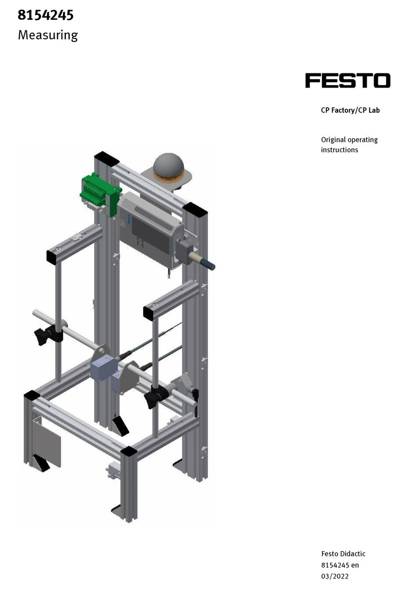
Festo CP-AM-MEAS Original operating instructions
Endress+Hauser
Endress+Hauser Liquiphant M/S FTL5 Series operating instructions

Once
Once BioShift Single Door UV-C Germicidal Chamber instruction manual
ABB
ABB A145-M65 Operation manual
Big Daishowa
Big Daishowa BBT30 Operation manual

MG
MG M8YS1 instruction manual
