PremierOne MUV7-100TR Installation and operating instructions
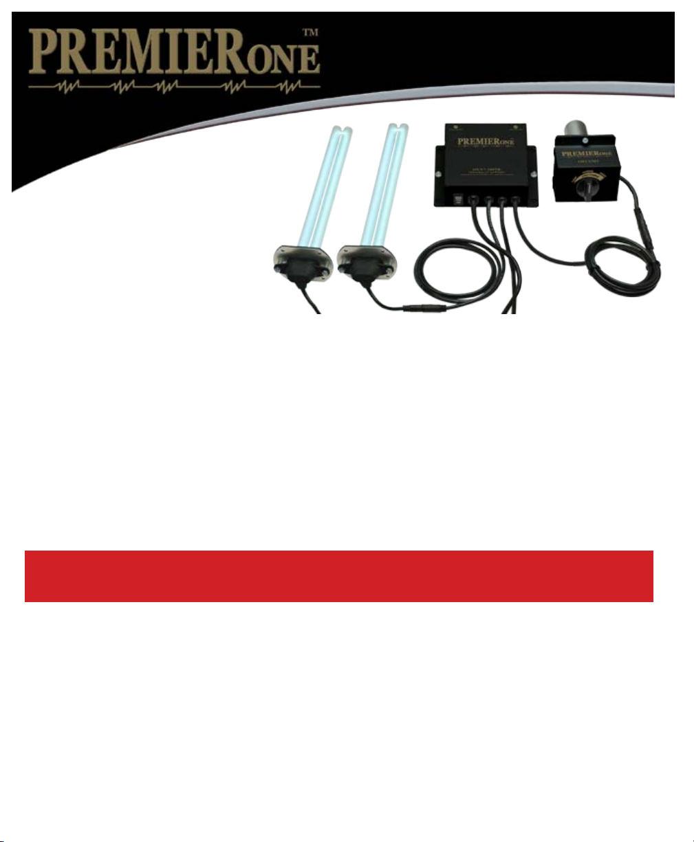
The following parts are included:
• Power Supply
• Two (2) Germicidal Twin H Lamp (packed in lamp box)
• One (1) Oxidation unit with lamp installed
• Sixteen (16) Sheet Metal Screws
When installing and using this electrical equipment, basic safety precautions
should always be followed including the following:
1. READ AND FOLLOW ALL INSTRUCTIONS.
2. Always be sure the unit is unplugged during installation or service procedures.
3. The ultraviolet light produced by the UV lamp is harmful to your eyes. Do not look directly at
the lamp. Should it become necessary to view the lamp, use UV-protected sunglasses.
Lors de l’installation et de l’utilisation de cet équipement, des précautions devront être suivies.
1- Lire et suivre les étapes attentivement.
2- Assurez vous de toujours débrancher avant l installation ou le service.
3- Ne pas regarder la lampe directement avec les yeux. Si nécessaire de le faire,
veuillez porter les lunettes de soleil contre les rayons U.V.
IMPORTANT: SAFETY INSTRUCTIONS
Important: Instructions de securité
• Four (4) Caution Labels
• Strain Relief Connector
• Alcohol Pad for Cleaning Lamps
• Installation & Maintenance Instructions
MUV7-100TR
MultiVoltage UVC System
Installation & Maintenance
Instructions
UNPACKING THE UNIT
Each unit is shipped with the germicidal lamps placed in a box with protective packaging. When handling lamps take
care to not touch the glass portion of the lamp with bare hands. Oils from the hands can cause “hot spots” which
reduce lamp life. Handle by the end caps or use a soft cloth. If you accidentally touch a lamp, use the alcohol pad
included or clean it using a soft cloth dampened with rubbing alcohol. The lamp is fragile and proper care must be
taken when removing from packaging.
INSTALLATION:
• Do not locate the germicidal lamp within 20” of plastic material that will be directly exposed to the UV light,
such as wiring, return-side humidier or certain types of air lters. Check with the lter manufacturer to see if their
material is UV resistant. Over time, UV light may degrade plastic.
• Do not touch the glass portion of the lamps with bare hands because oils from the hands can cause “hot spots”
which reduce lamp life. Handle either by the end caps or use a soft cloth. If you accidentally touch a lamp, wipe it
off, using the included alcohol cleaning pad or a soft cloth dampened with rubbing alcohol.
INSTALLING THE GERMICIDAL UNIT
MOUNTING GERMICIDAL LAMP AND POWER SUPPLY (supply or return side plenum)
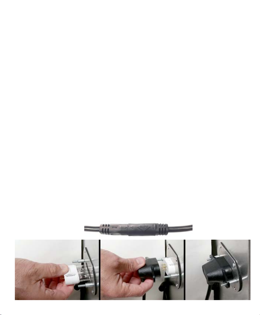
1. Unplug mid-cord connector by pressing the lock release (marked “PRESS” on the connector.) (see photo B)
Remove two thumb nuts holding moisture resistant lamp socket to mounting plate and remove from the plate.
2. Using the lamp mounting plate as a template, draw the hole pattern on the air duct in a suitable location.
3. Using a 1 1/4 inch Vari Bit, make two holes side by side. Clean off excess metal between the two
holes with tin snips. Alternately cut a 2” hole.
4. Peel off the gasket backing from lamp mounting plate and center over hole. Secure using four
self-tapping sheet metal screws provided. Repeat steps 1-4 for the second lamp.
5. Find a suitable location to mount the power supply making sure supply cord to ballast will reach 120 or
240 volt power supply. Mount the power supply using four self-tapping sheet metal screws provided.
6. Taking care not to touch the glass, hold the lamp by the end cap and insert fully into the base plate.
7. Insert the moisture resistant lamp socket over the plastic lamp end tting over the mounting studs,
secure using the two thumb nuts. (Photo A)
8. Route cord back to the moisture resistant lamp socket and reconnect mid-cord connector. Be sure to line up
arrows on the connector. (Photo B)
9. Adhere included UV Warning Label onto ductwork within six inches of UV lamp.
Photo A
Photo B

INSTALLING THE OXIDIZING UNIT (return side plenum only)
1. Cut a 1.75” - 2” hole for the unit.
2. Attach the unit to the air duct using the four self-tapping sheet metal screws provided.
(Airow direction is marked on the unit.)
3. Route oxidizing unit’s cord from the power supply, to the oxidizing unit and connect mid-cord connector.
Be sure to line up arrows on the connector. (see photo B)
TROUBLESHOOTING
With the selector switch in the ON position, the LED should light when power is supplied to the unit.
If the LED does not light with switch in the On position:
1. Check to be sure there is power to the unit.
2. Be sure lamp connectors are fastened securely.
3. If the LED still does not light, replace lamp(s).
4. If still not operating, replace ballast.
Note: Standard off-the-shelf lamps are not compatible with this unit. Use of improper lamps will void warranty.
WARRANTY
All electronic components carry a lifetime warranty to the original homeowner. In addition there is a four year
warranty from the date of installation for any subsequent owner. The manufacturer reserves the right to send
replacement parts or to replace the unit at its discretion. This warranty does not cover any labor or damage
resulting from improper installation or abuse. Use of any lamp other than a genuine PremierOne lamp designed
for this device will void the warranty.
The original lamps are warranted for a period of two years. This warranty does not cover lamps broken during
shipping, installation or as a result of improper handling.
All returns are routed through your contractor/wholesaler and must be approved and accompanied by an RGA#.
The limited warranties described above are in lieu of any other warranty, whether expressed or implied, written
or oral (including any warranty of merchantability or tness for a particular purpose.) This warranty gives you
specic legal rights. You may also have other rights which vary from state to state.
For Technical Support Call (800)982-1840 www.premieroneproducts.com
For Technical Support Call (800)982-1840 www.premieroneproducts.com
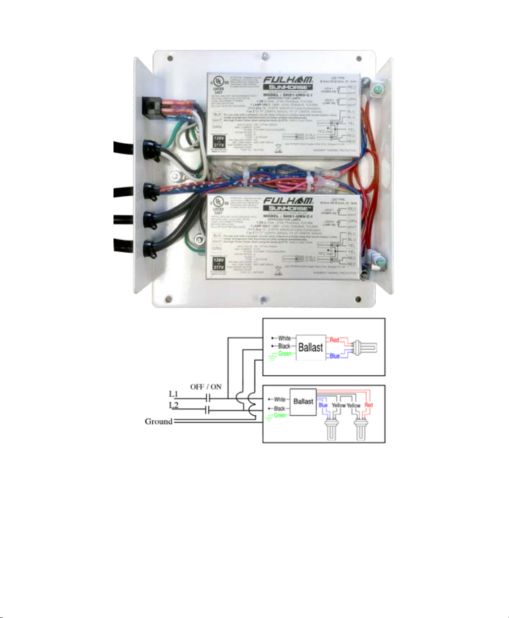
CORRECT WIRING FOR TRIPLE LAMP OPERATION.
WIRING/FUSE
The multivoltage ballast is self-adjusting and operates with voltages from 120 - 240 VAC. For 120V wiring
connect the black wire to L1, white wire to neutral, green wire to ground. For 240V wiring install 5 amp inline
fuses to both legs of power, then connect the black wire to L1, white wire to L2, green wire to ground. Be sure
power cord is secured with included strain relief connector.
The unit must cycle with the furnace blower. Wire unit to an EAC terminal or current-sensing relay to cycle the
unit with the system fan. If a 120 VAC EAC terminal is available, supply power to the unit from the EAC termi-
nal. Connect in accordance with local wiring codes. If there is no EAC terminal, interlock the UV unit with the
furnace blower using an appropriate alternate. Wire the unit in accordance with local wiring codes. After installing,
verify voltage is operating between 120 - 240 VAC with air handler operating.

MUV7-100TR shown mounted on a heat pump.
1. Using the lamp mount as a template, draw the hole pattern
on the air duct in a suitable location.
2. Using a 1 1/4 inch Vari Bit, make two holes side by side.
Clean o excess metal between the two holes with tin snips.
3. Peel o the adhesive backing of the gasket on backside of
mounting plate.
4. Center mounting plate on hole.
5. Use four self tapping screws provided to secure mounting
plate on the air duct.
Power Supply Dimensions:
Size (L x W x D)
10.625h x 5.75w x 1.75 d
Lamp Socket Dimensions:
Size (L x W x D)
3.5” x 2.75” x 1.625”
UVC
Lamp
Airow
UVC
Lamp
3099107
Oxidation
Unit
Oxidizing unit box size is 4 1/8” high x 4 1/8” wide.
Lamp socket size is 3.5” x 2.75” x 1.625”
Power box size is 6” x 5.75” x 1.5”
8 1/4”
3 1/4”
MAINTENANCE
This maintenance schedule is only a guideline, determined by average conditions. Actual conditions will dictate
the frequency of cleaning and/or replacement of lamps. Do not touch the glass portion of the lamps with bare
hands because oils from the hands can cause “hot spots” which reduce lamp life. Handle either by the end caps or
use a soft cloth. If you accidentally touch a lamp, clean it using a soft cloth dampened with rubbing alcohol.
CLEANING THE GERMICIDAL LAMP - Recommended interval: 12 months
1. Disconnect power to the unit.
2. Unplug mid-cord connectors by pressing the lock release (marked “PRESS” on the connector.)
Remove two thumb nuts holding moisture resistant lamp socket to mounting plate and carefully remove the
lamp socket with lamp from the mounting plate. Repeat this step for the second lamp.
3. Use a soft cloth moistened with rubbing alcohol to wipe down each lamp. If there is a large build-up of dust
particles, you may wish to use a can of air rst. Do not touch the glass portion of the lamps with bare hands.
4. Carefully slide the moisture lamp socket with lamp through the mounting plate into duct tting over the
mounting studs and secure using the two thumb nuts. (Photo A)
5. Reconnect the mid-cord connector. Be sure to line up arrows on the connector. (Photo B)
Repeat this step for the second lamp.
6. Supply power to the unit.
CLEANING THE OXIDATION UNIT LAMP - Recommended interval: 12 months
1. Disconnect power to the unit.
2. Unplug mid-cord connector by pressing the lock release (marked “PRESS” on the connector.) Remove the two
11/32” keps nuts and remove cover. Unplug the lamp connector from the end of the lamp then remove the lamp
holder using a 11/32 size nut driver. Remove the lamp by grasping the end cap and extract carefully.
3. Using a soft cloth moistened with rubbing alcohol, wipe down the lamp. If there is a large build-up of dust
particles, you may wish to use a can of air rst. Do not touch the glass portion of the lamp with bare hands.
4.
Slide the lamp back into the lamp opening. Reinstall lamp holder and plug the lamp connector to the end of the lamp.
5. Replace the cover and align the odor control knob with adjustment linkage by gently turning the knob
until linkage clicks into place. Secure cover using the two retaining nuts.
REPLACING THE LAMPS - Recommended interval: 24 months
Replacement lamps are available through your HVAC contractor.
Follow above procedure except #3 where you replace the lamps instead of cleaning them.
(Note: standard off-the-shelf lamps are not compatible with this unit. Use of improper lamps will void warranty.)
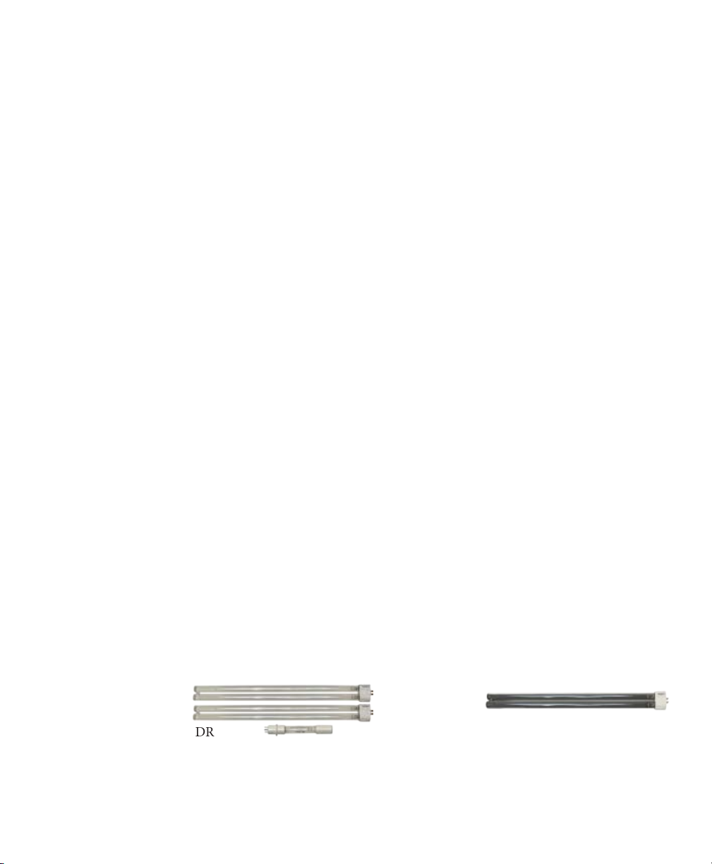
LSKTR100-16/5 LSKTR100-12/5 UVC16HCP-RF
LAMP KITS FOR MUV7-100DR
#LSKTR100-16/5 UVC lamp service kit with one (1) 5” 8-watt oxidation lamp and two (2) 16” 36-Watt UV lamps.
#LSKTR100-12/5
UVC lamp service kit with one (1) 5” 8-watt oxidation lamp and
two (2) 12” 24-Watt UV lamps.
#UVC16HCP-RF 36-Watt 16” UV lamp with built in reector.
#UVC12HCP-RF 24-Watt 12” UV lamp with built in reector.
This manual suits for next models
2
Table of contents
Other PremierOne Air Cleaner manuals

PremierOne
PremierOne P6100 User manual

PremierOne
PremierOne MUV-403H Installation and operating instructions

PremierOne
PremierOne MUV-401H Installation and operating instructions

PremierOne
PremierOne MUV7-50DR Installation and operating instructions

PremierOne
PremierOne MUV-401H Installation and operating instructions

PremierOne
PremierOne PureFlo P6100 User manual

PremierOne
PremierOne MUV7-100TR Installation and operating instructions

PremierOne
PremierOne 503-16 Installation and operating instructions

PremierOne
PremierOne MUV7-100DR Installation and operating instructions

PremierOne
PremierOne PureFlo P6100 User manual


