Presentation Switchers PS120 User manual

Users Guide
PS120
UPDATED: January, 2020 • PN: DOC-000032-01a
Presentation
Switchers
digital presentation systems

Page 2 Presentation Switchers, Inc.
Trademark Informaon
Trademark Informaon
Presentaon Switchers®, the “PS Box” logo or icon, and the names and marks associated with Presentaon
Switchers’ products are trademarks and/or service marks of Presentaon Switchers, Inc., and are registered
and/or common-law marks in the United States and various other countries.
All other trademarks are the property of their respecve owners.
Patent Informaon
Patent Informaon
The accompanying product is protected by one or more U.S. and foreign patents and/or pending patent
applicaons held by Presentaon Switchers, Inc.
Customer Feedback
Customer Feedback
We are constantly working to improve the quality of our documentaon, and we would appreciate your
feedback. Please send email to sales@PSwitchers.com.
© 2019-2020 Presentaon Switchers, Inc. All rights reserved.
Presentaon Switchers, Inc.
2324 Cheney-Spokane Road
Cheney, WA 99004 USA
No part of this document may be reproduced or transmied in any form or by any means, electronic or
mechanical, for any purpose, without the express wrien permission of Presentaon Switchers, Inc.
Under the law, reproducing includes translang into another language or format. As between the pares,
Presentaon Switchers, Inc., retains tle to and ownership of all proprietary rights with respect to the so-
ware contained within its products. The soware is protected by United States copyright laws and interna-
onal treaty provision. Therefore, you must treat the soware like any other copyrighted material (e.g., a
book or sound recording).
Every effort has been made to ensure that the informaon in this manual is accurate. Presentaon Switch-
ers, Inc., is not responsible for prinng or clerical errors.
Informaon in this document is subject to change without noce.

Page 3PS120 Users Guide
Contents
Contents............................................................................................3
Introduction.......................................................................................6
Introducing the PS120, a Multiformat HDMI, VGA, and USB-C Auto-
Switching Presentation Switcher ................................................................... 6
Getting to Know the PS120............................................................................. 7
Front View ....................................................................................................... 7
Back View ....................................................................................................... 7
Connections ..................................................................................................... 7
Installation.........................................................................................8
Connecting Input Devices............................................................................... 8
Compatible Input Devices ............................................................................... 8
HDMI Extenders.............................................................................................. 8
Connecting the Display................................................................................... 9
Compatible Displays ....................................................................................... 9
Image Resolutions .......................................................................................... 9
Stereo Audio Output........................................................................................ 9
Volume Control................................................................................................ 9
RS-232 Communication Interface .................................................................. 9
RS-232 Port Pinout ....................................................................................... 10
RS-232 Communication Settings.................................................................. 10
Power .............................................................................................................. 10
Internal Settings............................................................................................. 10
Basic Operation.............................................................................. 11
Selecting a New Source Device to Display ................................................. 11
Selecting a New Source Device to Display
(Using IR Remote).......................................................................................... 11
How Auto-Switching Works .......................................................................... 12
Connecting to the Switcher ........................................................................... 12
Disconnecting from the Switcher................................................................... 12
USB Type C Device Connection ................................................................... 12
Connecting to the Switcher using USB Type C (USB-C) .............................. 12
Quick-Charging Power.................................................................................. 12
Volume Control .............................................................................................. 13
Volume Control using IR Remote Controller ................................................. 13
Volume Control using Switcher Settings Application..................................... 13

Page 4 Presentation Switchers, Inc.
Contents (continued)
Switcher Settings App ...................................................................14
Introduction.................................................................................................... 14
Windows Mode View (default) ..................................................................... 14
Real Time Status Section.............................................................................. 15
Terminal Mode View....................................................................................... 15
Select Input (device to appear on the display) ........................................... 16
Turn Display On / Off..................................................................................... 16
Change Image Resolution............................................................................. 16
Volume Level.................................................................................................. 16
Mute Audio ..................................................................................................... 17
Display Control .............................................................................................. 17
Non-Use Timeout ........................................................................................... 17
Proximity Control........................................................................................... 17
LAN Settings .................................................................................................. 18
Debug Mode ................................................................................................... 18
Reset ............................................................................................................... 18
Restore System to Factory Defaults ............................................................ 19

Page 5PS120 Users Guide
[ This page is intenonally blank. ]

Page 6 Presentation Switchers, Inc.
Introducing the PS120, a Multiformat HDMI, VGA,
and USB-C Auto-Switching Presentation Switcher
Congratulaons and thank you for purchasing this Presentaon Switchers’ PS120!
The PS120 is a hybid AV + IoT presentaon switcher which combines the power of Presenta-
on Switchers audio-visual signal roung and display control with state-of-the-art Amazon AWS
cloud based control features for help desk support and performance monitoring.
In its simpliest form, the PS120 is a mul-format presentaon switcher that allows up to 3
HDMI, 1 VGA, and 1 USB Type C (USB-C) devices to all share a single HDMI display. Audio and
video content from connected VGA and USB devices will be converted to HDMI so the display
will only have one connecon to the switcher. Any audio associated with the selected input
devices will be extracted and sent to the RCA connectors as a pre-amp for local sound reinforce-
ment. Stereo audio desined for the display will connue to the display unempeded.
The PS120 Presentaon Switcher is an electronic device that allows up to 3 HDMI, 1 VGA, and
1 USB Type C “source” devices, such as a laptop computer and Sony® BluRay™ player, to share
user-supplied content on a single HDMI display, such as a high resoluon LCD display panel or
a LED projector (e.g. “output”). Where audio is including in the video data stream (like HDMI,
DisplayPort, USB-C, etc.) stereo audio from the selected device is extracted and output on two
(2) RCA connectors (le/right) designed for local sound amplificaon. The system auto-switches
to a new source when connected or powered on.
Input port 2 (see call-out on next page) is a designed for USB Type C (USB-C) devices, such as a
Google® Chromebook™, Samsung® Galaxy™ phones, Samsung® Galaxy™ Note, Dell® Laptops,
etc. The PS120 supplies power (up to 4 different voltage levels) to these devices in accordance
with USBPD 2.0 handshaking for the fastest charging capabilies available up to the power avail-
able to the PS120.
Users have numerous opons to control the PS120. By default, the PS120 will automacally
switch to any newly connected device. Users can manually select the device by touching the
Input Select buon. External control systems, like those manufactured by SP Controls, Crestron,
Extron, and AMX can ulize (a) the RS232 port, (b) the Ethernet port, (c) the IR port, and/or (d)
the USB 2.0 (USB-CDC) port.
Finally, the PS120 is an AV + IoT “Internet of Things” device. Presentaon Switchers developed
an Amazon AWS Client-Server applicaon designed specifically for help desk services. Using a
highly secure 256-bit encrypon system, help desk professionals are able to control the switch-
er, modify crical sengs, reset the system, and reset the system to factory defaults - all from a
browser based desktop or mobile device interface, from anyplace in the world.
Introduction
Page 7PS120 Users Guide
Getting to Know the PS120
The graphic below points out key aributes of the PS120.
Front View
Front View
Back View
Back View
Connections
Connections
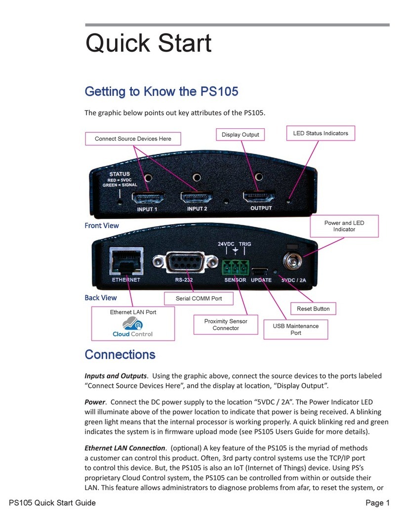
Device Inputs and Display Outputs. Using the graphic above, connect the source devices to
the ports labeled above as, “Connect Source Devices Here”, and the display at locaon, “Display
Output”, port. Connect audio, if applicable.
Amplifier or Powered Speaker Output ConnecƟons. Connect powered speakers or amplifier to
the Red and White RCA connectors denoted above as “Stereo Audio Output”.
Control Ports. Depending upon your control system, connecons can be made to the RS-232
port, Ethernet port, USB, and/or Proximity Sensor port..
Power. Connect the DC power supply to the locaon, “24VDC”, and the other end to your
110V/VAC power socket. The system LED will illuminate above “24VDC” locaon.
Connect Sources Devices Here
IR (Infra-Red) Sensor
Source Selector
Stereo Audio Output
Display Output USB Firmware Update
Proximity Sensor Port
Power & Indicator
RS-232 Port
Ethernet Port

Page 8 Presentation Switchers, Inc.
Installation
Connecting Input Devices
Input or source devices are connected on the back side of the PS120 using the connectors
labeled “Input 1” through “Input 5”. See image call-out on Page 5 of this manual.
Compable Input Devices
PS120 is compable with HDMI, VGA, and USB Type C devices. Use the appropriate connector
which matches your device connector type.
The PS120 also supports indirect connecons. The input device may be connected to a
connecvity box such as Extron® Cable Cubby™ or Alnex® Tilt ‘N Plug™ first before being
connected to the PS120. Oen, the PS120 itself will be connected under the table and hidden
from view.
HDMI Extenders
HDMI Extenders
The input may also be indirectly connected using an HDMI extender. By default, the PS120 keeps
its display informaon (EDID) local to each input. There is very lile delay from the me an input
device asks for the display informaon to the me the informaon is sent. A device connected
to an extender may “me-out” waing for a response from the display device. If a me-out
occurs, the input device will not send its content. It is important to use high quality extenders so
any delay caused by the extender technology is minimized and me-outs are less likely to occur.
The PS120 has a “pass through” mode that passes all display informaon requests directly to
the display. If this feature is enabled and the system is configured with extenders on the input
and output ports of the PS120 it is possible to have me-outs on certain input devices.

Page 9PS120 Users Guide
Connecting the Display
Displays (or other output devices) are connected on front side of the PS120 on the HDMI
connector labeled “HDMI Output”. See image call-out on Page 5 of this manual.
Compable Displays
Compable Displays
PS120 is compable with nave HDMI or DVI displays. Displays with DisplayPort connectors may
also operate properly with a HDMI to DisplayPort cable but the display itself must provide the
conversion from HDMI to Displayport (and many do automacally).
Image Resoluons
Image Resoluons
The PS120 supports resoluons up to UHDTV (3840 x 2160 @ 30Hz [4:2:2] or 60Hz [4:2:0]), all
HDTV resoluons, and VESA monitor resoluons up to 1920 x 1200. The key determining factor
is the clock rate. The PS120 supports clock rates up to 297MHz.
Stereo Audio Output
Stereo Audio Output
If external speakers are required, connect an RCA cable from the PS120 “Stereo Out” connectors
to your amplifier or powered speakers. See image call-out on Page 5, “Stereo Out”.
The stereo output is the audio extracted from the selected input.
Volume Control
Volume Control
Gain levels of the PS120 stereo output can be adjusted using the IR controller, RS232, USB,
or Ethernet controller. Adjustments can also be made via USB using Presentaon Switchers’
applicaon called Switcher Sengs.
See Basic Operaons, “Volume Control”, for details.
RS-232 Communication Interface
The PS120 uses an RS-232 serial interface to change aributes and behavior of the PS120.
The communicaon parameters are as follows: 115200 baud, 8 bit, no parity, and 1 stop bit.
The baud rate is fixed and unchangeable. Pins 2 (Rx), 3 (Tx), and 5 (GND) are used. In some
instances, the PS120 may have 24VDC power Pin 9.
235
235
COMPUTER SWITCHER
STRAIGHT THROUGH
SERIAL CABLE

Page 10 Presentation Switchers, Inc.
RS-232 Port Pinout
RS-232 Port Pinout
Computer PS120
Pin 2 Pin 2
Pin 3 Pin 3
Pin 5 Pin 5
Not Used Pin 9 (24VDC Power)
RS-232 Communication Settings
Baud Rate 115,200 Fixed
Packet Size 8 Bit
Parity None
Stop Bit 1
See Page 10 for more detailed discussions on RS-232 commands and/or review the
PS120 Programming Guide.
Power
Power
Using the AC to DC power supply shipped with the PS120, connect the round connector to the
PS120. The Power Indicator LED will illuminate above of the 24VDC locaon to indicate that
power is being received.
Internal Settings
Internal Settings
In most cases, the default sengs of the PS120 are sufficient for most applicaons. However,
there are mes when changes are needed. In these situaons, PS has created a Windows-based
applicaon which helps users and integrators make these changes. This applicaon is called “PS
Switcher Sengs” and can be downloaded from the PS120 webpage of the PS website. Further
explanaon is provided later in this document for this applicaon in the Switcher Seƫngs
secon.
Here are some sengs that can be viewed or changed:
• EDID table and resoluons
• Ethernet sengs
• Volume adjustments
• Auto-switching On/Off
• Display inacvity shutdown meout
• Proximity sensor On/Off

Page 11PS120 Users Guide
Basic Operation
Selecting a New Source Device to Display
To display a new source, press the Source Selector buon on the Front of the PS120 repeatedly
unl the LED on the Acve Source Indicator corresponds to the desired Source Port Selecon.
That image should now be visible on the Display Output and can be heard on the Stereo Audio
Output connectors.
Note: Selecng an input for a source that is not physcially connected will cause the output
display to indicate that the signal has been lost or disconnected.
Selecting a New Source Device to Display
(Using IR Remote)
(Using IR Remote)
From the IR Remote controller, shown below, select the Right or Lebuons unl the desired
Source is selected. If the front panel is viewable, you will see the Acve Source Indicator change
when each buon is pressed.
Connected Source Indicator

Page 12 Presentation Switchers, Inc.
How Auto-Switching Works
The PS120 uses a similar Auto-Sense, Auto-Switching strategy employed in many of Presentaon
Switcher’s products.
Connecng to the Switcher
The basic concept is that when someone connects her laptop or other device to the switcher,
the switcher recognizes the connecon, negotates the best resoluon for the display, and dis-
plays the laptop’s image on the display. If the display control feature is enabled and the display
supports CEC, the display will also turn on.
Disconnecng from the Switcher
When the user disconnects her laptop from the switcher the switcher begins a process to try to
find and display a different acve source. It begins by searching for acve sources beginning at
Input 1 and connuing through Input 5. Once it finds an acve input signal it routes that input
to the display. The hunt always begins at Input 1 and looks at each subsequent input aer.
USB Type C Device Connection
Many of today’s laptops and mobile devices now offer USB Type C ports. Many of these devices,
such as a Google Chromebook, support video out using this port. Simultaneously, the USB Type
C port will accept power, if available, to charge the laptop or mobile devices.
Connecng to the Switcher using USB Type C (USB-C)
Connecng a laptop or mobile device using the USB-C port is no different than connecng a
BluRay player or some other device using an HDMI port. If Auto-Switching is enabled, the image
from that laptop or mobile device will appear on the screen.
The PS120 supports USB-C Alternave “DisplayPort” mode. Thus, navely, the USB-C device
is sending the PS120 a DisplayPort video stream that the PS120 converts to HDMI for the lo-
cal display. It does this automacally.
Quick-Charging Power
Devices connected to the PS120’s USB-C port automacally get charged when connected using
the fastest method available for each device. The PS120 provides 5V, 9V, 15V, and 20V levels
depending upon the capabilies of the USB-C device connected. This negotaon process allows
different devices to be charged at the opmal voltage and speed as requested by the device
itself. The PS120 is limited to 30W of power which may limit the ability from some larger laptops
to accept power from the PS120.

Page 13PS120 Users Guide
Volume Control
Volume Control
Stereo audio extracted from the selected input will be routed to the RCA connectors on the back
of the PS120. These audio levels are adjustable (pre-amplified) to support powered speakers or
an external amplifier.
Adjustment to the stereo audio output can be achieved a number of ways. First, it can be ad-
justed using the IR remote supplied with the PS120. Second, volume can be adjusted using the
free soware called “Switcher Sengs” available on the product web page for the PS120. Third,
it can be adjusted via the Help Desk soware called “Cloud Control”. And, finally, it can be ad-
justed manually using USB (USB-CDC), RS232, and Ethernet terminal emulaon menu sengs.
Volume Control using IR Remote Controller
From the IR Remote controller, shown below, select the Up and Down buons unl the desired
Volume Level is determined. One will not see any indicaon of the adjustment from LEDs or
other indicators on the device itself.
Volume Control using Switcher Sengs Applicaon
See next secon, Advanced Features, for details on how use the program “Switchers Sengs” to
adjust real me sengs of the PS120.

Page 14 Presentation Switchers, Inc.
Introduction
Introduction
PS’ Switcher Sengs is a Windows applicaon which allows users and integrators to change the
behavior of PS’ presentaon switchers in real me.
Connect a Windows-based PC to the PS120 using a USB Type A to USB Micro-B cable.
Windows Mode View (default)
This screen view uses standard Windows-style menuing to modify the behavior (sengs) of the
Switcher Settings App
Real Time
Status Section
Switcher
Settings
Communications
Status

Page 15PS120 Users Guide
presentaon switcher.
Real Time Status SecƟon
The status secon of the Windows Mode view displays what the switcher “thinks” it is sensing
from the inputs and outputs. In the example above, the switcher is seeing acve video data on
all of its input ports with the excepon of HDMI-4. Either HDMI-4 does not have a cable con-
nected or the source connected is not sending video data.
VGA-1 is currently selected and sending out a 1920x1080p video stream with a RGB_Limited
color format configured for a DVI display.
Terminal Mode View
Terminal Mode View
Years ago, people used clunky monochrome computer “Terminals” that were connected to mid-
size or mainframe computer systems. In this mode, the system looks very similar to those old
Terminals.
This interface is a menu driven system used to modify switcher features. The HELP menu is
shown in the Terminal mode image below.

Page 16 Presentation Switchers, Inc.
Select Input (device to appear on the display)
Using the Input Select pull down menu, select down-arrow and the desired input. Once selec-
on has been made the image from that device will appear on the display and audio from that
device will be heard on the display and the RCA connectors.
Turn Display On / Off
Using your mouse, select “On” to turn the display on and “Off” to turn offthe display. The indi-
cator to the right (Off/ On) always shows the current status of the Display. This feature requires
CEC display control to be acve and that the display itself has CEC capabilies.
Change Image Resolution
To change the resoluon, we advise the input to use the preferred resoluon of the display
using a data structure called EDID (Extended Display Idenficaon Data). The user can change
this seng by selecng the EDID Resoluon seng as needed. To do this, select the small down
arrow to the right to see the available resoluons of which to choose.
The system will require a reset for the PS120 and the input to recognize the new resoluon set-
ng.
Volume Level
Volume Level

Page 17PS120 Users Guide
This feature only effects the audio level on the RCA pre-amp outputs. To adjust the audio level,
press on the Blue Dot associated with the Volume as show below. Click and drag to the desired
level. The level is indicated next to the mouse as the volume is adjusted.
Mute Audio
Mute Audio
This feature only effects the audio level on the RCA pre-amp outputs. To mute the audio, select
the speaker on the Volume control adjustment tool. In the example above, the audio has been
muted. Volume will be restored to the previous level by selecng the muted-speaker icon.
Display Control
Display Control
This feature turns on and offthe display when necessary. This feature is only applicable if the
display supports HDMI-CEC (Consumer Electronics Control). In this mode, when a person comes
into a conference room and connects her laptop to the system, the display will automacally
turn on and her laptop will appear on the screen.
Non-Use Timeout
Non-Use Timeout
When users disconnect their laptops and computers from the presentaon, the PS120 will wait
this many seconds before the switcher automacally shuts down the display. This feature is only
applicable when CEC and Display Control is enabled.
Proximity Control
Proximity Control

Page 18 Presentation Switchers, Inc.
A proximity sensor ships with each PS120. This devices measures heat in the presentaon space.
If there is nobody in the presentaon space and the display is sll turned on, the switcher will
wait 2-10 minutes before shung the display off. The number of minutes is set using a rotary
dial on the proximity sensor itself.
LAN Settings
LAN Settings
When connected to an appropriate router, DHCP (Dynamic Host Configuraon Protocol) will
allow the switcher to get its IP sengs from the router. When not using DHCP, one must use the
stac IP sengs to properly address itself to the network (and internet). This part of the Switch-
er Sengs applicaon allows the modificaon of these sengs. Select Update when done and
reset the switcher to connect to the network.
Debug Mode
Debug Mode
This seng is used primarily by inhouse staffto help a person detect problems in their audio-
visual system. One must use the Terminal Mode to see the messages issued by the debug mode
seng.
Reset
Reset
By touching the “Reset Device” buon, the PS120 will be reset similar to a peron turning offthe

Page 19PS120 Users Guide
power and then turning the power back on. However, this event can be achieved using so-
ware.
When a reset occurs, the PS120 uses the last-stored sengs of the switcher. This means that
the switcher will try to restore inputs, resoluon, and audio sengs to the way they were prior
to the reset.
Restore System to Factory Defaults
The “Factory Def” or factory defaults buon restores all factory detault sengs that were used
when the PS120 was first sent to the customer then performs a soware reset. However, this
funcon does not reset the LAN Sengs.

© 2020 Presentaon Switchers, Inc. All rights reserved.
Presentaon Switchers, Inc.
2324 Cheney-Spokane Road
Cheney, WA 99004 USA
sales@pswitchers.com
Other manuals for PS120
1
Table of contents
Other Presentation Switchers Switch manuals

Presentation Switchers
Presentation Switchers PS190 User manual

Presentation Switchers
Presentation Switchers PS110 User manual

Presentation Switchers
Presentation Switchers PS120 User manual

Presentation Switchers
Presentation Switchers PS510 User manual

Presentation Switchers
Presentation Switchers PS112 User manual

Presentation Switchers
Presentation Switchers PS190 Manual

Presentation Switchers
Presentation Switchers PS190 User manual

Presentation Switchers
Presentation Switchers PS105 Operating and maintenance instructions

Presentation Switchers
Presentation Switchers PS100 User manual

Presentation Switchers
Presentation Switchers PS112 Manual