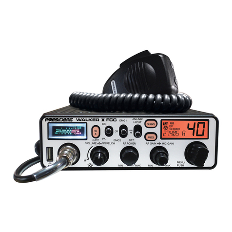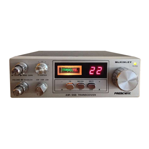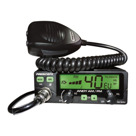
IMPORTANT: Маке sure that the antenna, power source,
and microphone are connected before you operat).
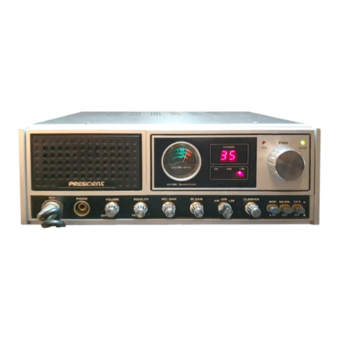
1} Set t'ne CB-РА switch to CB position.
2) Turn the unit on by setting the Power Switch to On
position. Npw the meters, Channel Indicator, and Function
Indicators will be illuminated.
3) Temporarily. set the Mode Switch in AM position.
4) Set the Squelch Control in fully counterclockwise
position and ajust the AF Gain control for a comfortable
listening level.
5) Listen to the background noise from the speaker. Turn
the Squelch Control slowly clockwise until the noise just
disappears (no signal should be present). Leave the Squelch
Control at this setting. The Squelch Control is now pro-
perly adjusted. The receiver will remain quiet until a singal
is actualy received. Do not advance the Squelch Control
too far clockwise or some of the weaker signais will not be
heard.
6) Depress the Clarifier and set it to the center (12 o'clock)
position.
7) Seloct a desi.red mode of operation, CW, FM, AM, USB
or LSBand adjust the Clarifier.
8) Select a channel you desire by the Band Select switch,
then by the Channel Selector.
Note. If you want to operate in between charnels, pull
out the clarifier knob and rotate it upscale or downscale.
(This also affects in transmitting mode.)
Operating Procedure То Transmit
1) Select the desired channel and mode of transmission.
2) If the channel is elear, depress the Push-to-Talk switch
on the microphone. Speak in a normal tone of voice.
Standby-Beep
A special provision has been bullt in you radio to give other
stations a sign which tells that you are turning to receive.
Without needing switching operation toactivatetiisfeature,
a been tone is automatically transmitted at each time you
release the push-to-talk switch on the microphone to turn
to receive mode.
Microphone gain control
A preamplifi8r circuit is built into the radio to increase the
microphone gain. E periment with the control for setting
that will best suit your individual use.
Note. When the microphone gain control is set to
ma imum, ambient noise may also be picked up by the
microphone. In high noise situations, low. microphone gain
setting may produce the best results.
The microphone gain control is also used to adjust PA
loudness.
Qperating Proced re To Receive
To use this feature oi th8 transceiver, a speaker having a
voice coil impédance ôf 8 to 16 ohms and a power handling
capability of at least »3 watts should be connected ta the
PA SP jack on the real; panel. Be sure that there is physical
séparation between the microphone and the PA speaker
itself. If the PA speaker is located vsry close to the micro
phone, acoustic feedback will resuit when the PA amplifier
is operated at high völume (or when PA is used indoors),
Adjustment of PA volume is made with the MIC GAIN
control. •V
SWR Measurement
Most antennas are factory tuned, but the antenna efficiency
may be peaked by slightly adjusiing the length of antenna
using the SWR meter built into the unit. This adjustment
may improve the antenna standing wave ratio (SWR). The
SWR permits you to détermine how well matched the
antenna and its cables are to your transcsiver.
1) Set the unit in the" receive mode as instructed under the
Operating Procedure to Receive section.
2) Set the Mode switch to AM position; the SWR-Cal 6)
switch to the Cal position.
3) Press the Push-to-Talk switch on the microphone and
turn the Calibrate Control clockwise (past dick) so that the
SWR meter pointer e actly coincidos with the Set mark
on the scale. Release the Push-to-Talk switch.
4) Set the SWR-Cal switch to the SWR position and depress
the Push-to-Talk switch again. The SWR of your antenna is
read directly on the scale.
Note: An SWR below 2 or less is desired as this indicates
that over 95% of the transmitted power is broadeast into
the air.
P blic Address Operation
- 6 -
