2.2 The Screen
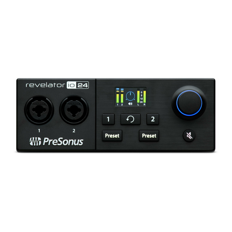
The screen displays metering, preset selection, and other important information.
The following information is displayed on Revelator io24’s Home screen. This is the default screen you’ll
see when you first use Revelator io24.
1. Input Meters. These meters
indicate the input level of the
analog inputs on your Revel-
ator io24. The red Clip indic-
ator will light when your input
signal reaches -0.5 dBFS. At
this level, the signal will
begin to overload the ana-
log-to-digital converters and
exhibit signs of clipping. Use
the gain controls to keep the
signal below this level.
2. Output Meters. These
meters indicate the signal
level received from the first
two driver returns (Main
Left/Right). These meters display the signal level before the main output level control.
3. Output Volume/Blend. This indicates output volume of the currently-selected output (Headphones
or Mains) just like a volume knob—as well as Monitor Blend.
4. Encoder status. Lets you know if the Encoder Knob is controlling Headphone output level, Main out-
put level, or monitor Blend (direct vs. hardware.)
5. USB Status indicator. Confirms that Revelator io24 is connected via USB and functioning normally.
6. Preset indicators. These lights indicate the preset selection of both channels. If presets are
bypassed, both will be dark.
7. Input Clip indicator. Lights red when the incoming signal is too loud for the converter, causing dis-
tortion.
8. Output Clip indicator. Lights red when the outgoing signal is too loud.
9. Stereo link indicator. This icon informs you that Channels 1 and 2 are configured for use as a single
stereo channel for use with stereo instruments like keyboards. This feature can be activated in Univer-
sal Control, or by pressing both channel buttons on Revelator io24 simultaneously.
10. +48v indicator. Informs you if +48v power has been activated—required for most condenser micro-
phones.
WARNING: Phantom power is only required for condenser microphones and can severely
damage some dynamic mics, especially ribbon mics. Therefore, switch phantom power off
when it is not required. Consult the user documentation that came with your microphone
before engaging phantom power.
XLR connector wiring for phantom power:
Pin 1 = GND Pin 2 = +48V Pin 3 = +48V
The following information is displayed on Revelator io24’s Channel screens. Press Channel Select
2.2 The Screen 14


