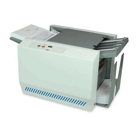
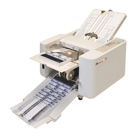
Pressure Seal PS 100 User manual

Pressure Seal Group
Technical Manual
PS 100
Compact Pressure
Folder and Sealer
Telephone +44 (0) 19 6273 5777
E-mail service@pseal.co.uk
Website www.pressure-seal.com
ISSUE 1.

i
Contents
Chapter One – Description...................................................1
General Description ................................................................................................2
Which Side Is Which?.............................................................................................3
Features..................................................................................................................4
Folder Components..........................................................................................5
Document Guides .....................................................................................5
Feed Roll...................................................................................................5
In-Feed Table............................................................................................5
Folding Plates...........................................................................................5
Folding Rollers..........................................................................................5
Jam Detection and Document Counting Circuitry .............................................6
Conveyor and Outfeed Sensors................................................................6
Operator Controls .............................................................................................6
Batch Counter...........................................................................................6
Illuminated Power Switch..........................................................................6
Run Switch................................................................................................6
Stop Switch...............................................................................................6
Power and Safety Components ........................................................................7
Mains Lead ...............................................................................................7
Top Cover.................................................................................................7
Sealing and Stacking Components...................................................................7
Pressure Bolts...........................................................................................7
Sealing Rollers..........................................................................................7
Output Tray...............................................................................................7
Technical Information..............................................................................................8
Folder/Sealer Specifications .............................................................................8
Construction..............................................................................................8
Size...........................................................................................................8
Weight.......................................................................................................8
Power........................................................................................................8
Speed........................................................................................................8
Environment..............................................................................................8
Document Specifications...................................................................................8
Weights.....................................................................................................8
Sizes.........................................................................................................8
Fold Configuration.....................................................................................8
System Overview....................................................................................................9

ii
Chapter Two – Installation....................................................10
Site Requirements ..................................................................................................11
Floor Space Requirements ...............................................................................11
Power Requirements.........................................................................................11
Places to Avoid .................................................................................................11
Unpacking the PS100 .............................................................................................12
To Unpack the PS100.......................................................................................12
Inspecting the PS100..............................................................................................14
Setting up the PS100 and Verifying Operation........................................................14
Training the Operator..............................................................................................15
Finishing the Installation..........................................................................................15
Chapter Three – Electrical Operation..................................16
Electrical Components List......................................................................................17
Theory of Operation................................................................................................18
Interrupt Operation............................................................................................19
Jam Detect Theory of Operation.......................................................................19
Board Functions................................................................................................22
Troubleshooting Electrical Components .................................................................25
Chapter Four – Assemblies and Adjustments ...................26
Covers and Panels..................................................................................................27
Removing the Infeed Panel...............................................................................28
Removing the Outfeed Panel............................................................................28
Removing the Operator Side Cover..................................................................29
Removing the Non-Operator Side Cover ..........................................................29
Document Feed System..........................................................................................30
Removing the Feed Roll and Paper Separator .................................................30
Replacing the Feed Roll and Paper Separator..................................................31
Removing the Clutch.........................................................................................31
Document Folding System......................................................................................32
Removing the Fold Rollers................................................................................32
Document Sealing System......................................................................................33
Removing the Sealer Chain..............................................................................33
Replacing the Sealer.........................................................................................34
Adjusting the Sealer Roller Pressure................................................................34
Electrical Systems...................................................................................................35
Removing the Cover Switch..............................................................................35
Removing the Infeed Sensor.............................................................................36
Removing the Outfeed Sensor..........................................................................37
Removing the Motor..........................................................................................38

iii
Chapter Six – Operation Errors............................................39
Troubleshooting Guide............................................................................................40
Chapter Six – Preventative Maintenance............................43
Before You Begin....................................................................................................44
Cleaning the PS100................................................................................................44
Lubricating the PS100.............................................................................................45
Inspecting the PS100..............................................................................................45
Chapter Seven – Illustrated Parts List ................................46
Recommended Spares for Engineers.....................................................................46
PS100 chassis .......................................................................................................47
Paper Guide Plates.................................................................................................48
Motor and Mount.....................................................................................................49
Fold Rollers.............................................................................................................50
Top Fold Roller .......................................................................................................51
In-Feed Shafts ........................................................................................................52
Sealer......................................................................................................................53
Gears and Clutch....................................................................................................54
Baseplate................................................................................................................55
Levers and Fold Plate Stubs...................................................................................56
Springs....................................................................................................................57
Sprockets and Chains.............................................................................................58
In-Feed Tray ...........................................................................................................59
Fold Plates..............................................................................................................60
Covers.....................................................................................................................61
Feed Pad Adjuster Shaft Assembly ........................................................................62
Feeder Wheel Assembly.........................................................................................62
Sealer Assembly.....................................................................................................63
Sealer Sensor Bracket Assembly............................................................................64
Baseplate Assembly ...............................................................................................65
Clutch Gear Assembly............................................................................................66
Infeed Sprocket Assembly ......................................................................................66
In-Feed Tray Assembly...........................................................................................67
First Fold Plate Assembly .......................................................................................68
Second Fold Plate Assembly..................................................................................69
Operator Side Cover Assembly...............................................................................70
Infeed Cover Assembly...........................................................................................71
Outfeed Cover Assembly........................................................................................72

iv
Diagrams
Figure 1. Types of Fold Produced by the PS100........................................................2
Figure 2. The Sides of the PS100 ..............................................................................3
Figure 3. The Features of the PS100.........................................................................4
Figure 4. The PS100’s Components (Operator Side View)........................................9
Figure 5. The PS100’s Components (Non-Operator Side View)................................9
Figure 6. Unpacking the PS100 (export only).............................................................13
Figure 7. PS100 Circuit Board....................................................................................20
Figure 8. PS100 Circuit Board Mk II...........................................................................21
Figure 9. Schematic Diagram.....................................................................................23
Figure 10. Schematic Diagram Mk II............................................................................24
Figure 11. PS100 Covers.............................................................................................27
Figure 12. Removing the Feed Roll and Paper Separator............................................30
Figure 13. Removing the Clutch...................................................................................31
Figure 14. Removing the Sealer Chain ........................................................................33
Figure 15. Replacing the Sealer...................................................................................34
Figure 16. Removing the Cover Switch........................................................................35
Figure 17. Removing the Infeed Sensor.......................................................................36
Figure 18. Removing the Outfeed Sensor....................................................................37
Figure 19. Feed pad shaft and stop cam......................................................................42

Page 1
Chapter 1
Description
This chapter introduces you to the Pressure Seal PS100 Folder/Sealer. Use the
information here to familiarise yourself with component names and locations, and to
gain a better understanding of the physical and performance characteristics of the
PS100.
In Chapter 1 you’ll find the following topics:
•General description
•Which side is which?
•Features
•Technical information
•System overview

Page 2
General Description
The Pressure Seal PS100 Folder/Sealer is a compact, portable unit requiring no
more than desktop space to operate. Because of it’s compact size, the PS100 fits a
variety of work spaces and can be moved easily (the PS100 weighs 80kg)
anywhere it’s needed.
The PS100 produces self-mailers at speeds of up to 4000 documents per hour. In
one smooth operation, the PS100 folds and seals single sheets into self-mailers
quickly and economically. Pressure activated cohesives provide an instantly secure
seal on all sides of the document, whether you use a “V”, “C” or “Z” fold.
'V' fold 'C' fold 'Z' fold
Figure 1. Types of fold produced by the PS100.

Page 3
Which side is which?
The terms “infeed”, “outfeed” and “operator side” are used throughout this manual
to identify the sides of the PS100 (see figure 2 below).
•The infeed is the side into which documents are fed.
•The outfeed is the side out of which the finished mailers exit.
•The operator side of the PS100 is the side on your right when you’re facing the
infeed of the PS100 and has all of the operator controls mounted on it.
infeed
outfeed
non-operator side
operator side
Figure 2. The sides of the PS100.

Page 4
Features
This section guides you through the features of the Pressure Seal PS100
Folder/Sealer. The component names introduced in this section are used
throughout this manual.
second fold plate
first fold plate
fold rollers
sealer rollers
sealer pressure bolts
batch counter
stop switch
run switch
illuminated power switch
fixed document guide
feed roll
adjustable side guide
infeed tray
output tray
top cover
Figure 3. The features of the PS100.

Page 5
Folder Components
Document guides
The document guides keep the documents aligned so the feed roll feeds each one
squarely. The guide nearest the operator side of the PS100 is adjustable to
accommodate various sheet widths.
Feed roll
This provides reliable single-sheet document feeding into the folding area. The roll
requires no adjustment.
In-Feed table
The feed table holds the stack of documents allowing them to be fed by the feed
roll. The spring-loaded table presses the documents against the feed roll,
automatically providing the correct pressure to allow only one document at a time to
be fed into the folder.
Folding plates
These provide for simple “V” (centre or half) folds, “Z” (zigzag) folds or “C” (letter)
folds. The plates are adjustable to accommodate various document lengths.
Folding rollers
These work in conjunction with the folding plates to produce folds. The rollers feed
the document into and out of the folding plates. The top roller is removable, which
aids recovery of mishandled documents.

Page 6
Jam detection and document counting circuitry
Conveyor and outfeed sensors
These monitor the flow of paper and should a misfeed occur they immediately shut
down the PS100, minimising the risk of spoiled documents. The sensors also
provide input to the counters.
Operator Controls
Batch counter
There are two types of batch counter available. The standard counter indicates the
number of documents in the current batch (since it was last reset) and has a push
button reset. There is an optional counter available for the cumulative total, and this
may only be reset by a service engineer.
Illuminated power switch
The power switch is illuminated when the PS100 is connected to the mains supply.
Run switch
The run switch lights when:
•Documents are properly loaded on the feed table, and
•There are no mishandled documents in the PS100
When the run switch is lit:
•Momentarily pressing the run switch processes one document
•Pressing and holding the run switch for two seconds processes all loaded
documents
Stop switch
Pressing the stop switch stops the PS100 after the document currently being fed is
processed. You can stop the PS100 anytime while documents are processing.
The stop switch flashes when there is an operating error. To clear an error
condition:
•Remove the lid from the PS100
•Clear any mishandled documents
When the top cover is replaced, the PS100 automatically resets the error condition.

Page 7
Power and safety components
Mains lead
Supplies electrical power to the PS100.
Top cover
Provides access to the folding and sealing components. The cover has a safety
interlock that disables operation of the PS100 when the cover is removed. The
cover must be removed to reset an error condition.
Sealing and stacking components
Pressure Bolts
Let you release the pressure on the sealing rollers for clearing mishandled
documents.
Sealing rollers
Provide the pressure required to tightly seal the edges of the document.
Output tray (stacker)
Collects the self-mailers and stacks them for easy removal.

Page 8
Technical information
Folder/Sealer specifications
Construction
Formed sheet metal steel side frames with ABS shell
Size
685mm(L) x 495mm(W) x 375mm(H) (excluding output tray of 115mm)
Footprint 675mm(W) x 495mm(L)
Weight
80kg
Power
110v AC, 60HZ, 5A
230V AC, 50HZ, 2.7A
Speed
4,000 documents per hour maximum
Environment
Operating 10°– 40°C
5% - 50% humidity
Non-operating 5°– 50°C
5% - 80% humidity
Feeder Capacity
150 sheets
Noise
72dB
Document Specification
Weights
60 gsm minimum; 145gsm maximum
Sizes
175mm (6.9in) x 100mm (4in) minimum
216mm (8½in) x 385mm (14in) maximum
Fold Configuration
Z, V and C folds

Page 9
System overview
This section illustrates the locations of the major parts of the PS100 Folder/Sealer.
Refer to figures 4 and 5 below.
outfeed sensor
infeed sensor
filter sealer roller gears
clutch/clutch gear clutch drive gear
fold rollers
fold roller gears
Figures 4 and 5. The PS100’s components.

Page 10
Chapter 2
Installation
This chapter describes the site requirements and the sequence of tasks you must
perform to successfully install the PS100 Folder/Sealer.
Installation tasks include:
•Site requirements
•Unpacking the PS100
•Inspecting the PS100
•Setting up the PS100 and verifying operation
•Training the operator
•Finishing the installation

Page 11
Site Requirements
Space requirements
2.5m x 2.75m is required. This area allows approximately 1m of clear space around
the machine.
Power requirements
•Input voltage: 240 volts UK (210/220V Europe) (110V USA)
•Input frequency: 50 Hz UK/Europe (60Hz USA)
•Input current: 2.7 amperes
•Mains lead: 2m three-pin 5A (male plug with BSI363A connector)
2m Schuko lead (Europe)
2m NEMA 5 power cord (USA)
Places to avoid
•Avoid placing the PS100 under a blowing air duct or beside an open window.
Strong air currents can disrupt document feeding, resulting in mishandled
documents.
•Avoid electrical outlets controlled by wall switches or timers.
•Avoid locations subject to direct sunlight, excessive heat, moisture or dust.
•Store Pressure Seal documents away from UV light sources. UV light degrades
adhesives, shortening document shelf life.

Page 12
Unpacking the PS100
The PS100 is shipped fully assembled in a wooden crate. Although some variation
in packing is possible, the unit should arrive at the customer site as described
below.
Warning: The PS100 weighs 80 kg. Therefore, two people are required to lift the
PS100 from the crate’s skid onto the work surface. Do not pick up the PS100 by
the infeed tray.
To unpack the PS100
1. Locate the crate immediately next to the location where the PS100 will be set up
and operated.
2. Remove the screws that secure the top of the crate to the base of the crate, and
then lift the top off the base.
3. Remove the four screws securing the transit plates to the base of the crate
(shown in the following diagram).
4. Using two people, lift the PS100 from the base and onto the work surface.
5. Remove the four screws and washers securing the transit plates to the PS100
and situate the PS100 as required.

Page 13
Figure 6. Unpacking the PS100 (export only).

Page 14
Inspecting the PS100
1. Visually inspect the exterior of the PS100 for damage.
2. Remove the left and right (operator) sides covers and inspect all electrical
connections. Make sure none have come loose during shipping.
3. Replace the covers.
4. Power up the PS100. (See “powering up the PS100” in the operator manual for
detailed procedures.)
5. Press the run switch for a few seconds. Listen for any unusual noises (grinding,
clattering etc.). Troubleshoot if necessary.
Setting up the PS100 and verifying operation
1. Adjust the stacker to accommodate the mailers.
2. Remove the top cover and set up the folder. (See “Setting up the folder” in the
Operator Manual for detailed procedures.)
3. Load documents. (See “Loading documents” in the Operator Manual for detailed
procedures.)
4. Start up and test the PS100. (See “Starting up and testing the PS100” in the
Operator Manual for detailed procedures.) Verify the following:
•Straight folds. If the folds are not straight on the document, check the
document guides on the feed table are parallel.

Page 15
Training the operator
Operator training is an important part of the installation process, and is the key to
proper machine performance. By doing a thorough job in this area, you can reduce
the number of service calls for typical performance issues such as document
mishandling. Take the time to make sure the operator understands his or her role in
making the PS100 a successful performer.
Using the Operator Manual as a guide, review the following information with the
person(s) who will be responsible for operating the PS100.
1. Explain the features of the PS100 and the major components the operator will
use to set up and operate the PS100.
2. Demonstrate the tasks required in setting up, loading, and operating the PS100.
Stress the importance of properly installing the top folding roller and folding
plates.
3. Point out the area of the PS100 that require periodic maintenance. Emphasise
the importance of cleaning the machine on a regular basis.
4. Discuss the error conditions that can occur with the PS100, and explain the
cause and how to correct the problem.
5. Review the PS100’s technical specifications.
6. Explain document curl and show the different ways you can set up and load
documents.
Finishing the installation
Once you’ve trained the operator, make sure you complete the following steps to
successfully complete the installation.
1. Review with the customer the service agreement coverage on the PS100.
2. Explain how to place calls for service and to the Help Desk.
3. Provide procedure for ordering cleaning kits.
4. Record the model and serial number.
Table of contents
Other Pressure Seal Folding Machine manuals
