Prestige medical 2100 Classic 210006 User manual

Page 1 of 9

Page 2 of 9
CONTENTS
P3 - Decals, displays and controls
P4 - Introduction.
- Key to Pictures.
- Getting Started.
P6 - Continued Operation.
P7 - roubleshooting.
P8 - Model Information.
P9 - Additional Information.
Page 3 of 9

Page 4 of 9
Thank you for choosing the Prestige Medical Series 2100ClassicAutoclave designed to sterilize solid, un-
wrapped instruments in a 121°C saturated steam process. fter removing from the box, please check for any
transit damage. If any damage to the unit is found, please contact your supplier immediately.
Together with this unit and operating manual, you will find the following:
♦ Electrical mains cord ♦Instrument furniture (Baskets)
♦Performance test certificate ♦Warranty registration card
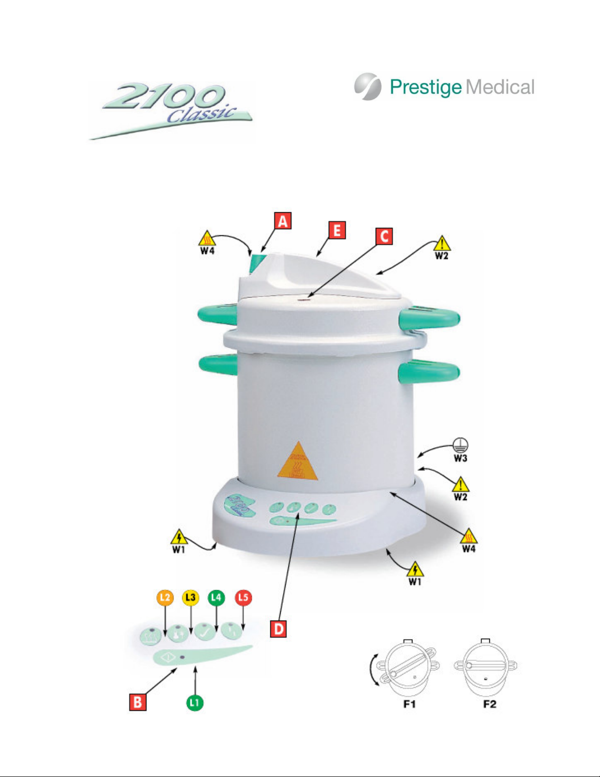
The following descriptions refer to the pictures of the controls, display lights and operating symbols on Page 3 of
this manual.
Controls:
A - Depressurisation Valve
B -Start Cycle Button
C -Pressure Rise Indicator
D - Display Panel
E -W RNING! The top moulding is not a handle -
do not use to remove the lid or lift the autoclave -
use the side handles.
HOTP RTS! - Do Not Touch the top moulding
during and after a cycle.
Figures:
F1 -Lid aligned with body, turn clockwise to close
F2 -Lid in closed position
Display Lights:
L1 - Power On light - illuminates GREEN
L2 - Heating Light - illuminates OR NGE
L3 - Sterilizing Light – Illuminates YELLOW
L4 - Sterilizing complete Light – Illuminates GREEN
L - Fault Light – Illuminates RED
Warning Symbols:
W1 – Warning, Caution, electric shock hazard.
W2 – Warning, Read manual before using the
autoclave.
W3 - Warning, unit must be earthed/grounded.
W4 – Warning, heat hazard.
Before using the autoclave for the first time please take time to read the following pages to familiarize your self
with the operation of the unit. ll personnel who operate or maintain the autoclave must be trained in its
operation and safe use. The utoclave is very easy to use. By following this simple operating sequence in
conjunction with the pictures of the utoclave, its controls, display panel and operating symbols (page3), you
will be able to ensure your instruments are correctly sterilized every time.
1. Water
Fill the unit to the water level line on the inside of the chamber with 0.75 litres of distilled or de-ionised
water. DO NOT USE TAP WATER OR OVERFILL.
2. Loading (Solid Instruments)
Do not attempt to sterilize lumened instruments or dental hand pieces in the unit.
a) Prior to sterilization, all instruments must be thoroughly cleaned and inspected to ensure they are not
damaged and will function properly.
b) Place UNWR PPED and W SHED instruments ONLY, plus a Chemical Indicator Strip, into a suitable
instrument container, eg. basket or cassette. (Baskets and cassettes are perforated to permit rapid and
complete steam penetration.)
c) Place all instruments in the vertical, open, unlocked position; ensuring face-to-face contact between flat
surfaces is avoided.
d) Smaller instruments, which can be laid horizontally within the instrument container, should be placed in
such a way that all surfaces will be exposed to steam.
NOTE: Point to point contact will not impede sterilization, but significant contact between flat surfaces will.
Introduction.
Key to pictures, Displays and Symbols
.
WARNING!
Do not touch body or lid as these parts
become hot when the autoclave is in
operation
Getting Started.
WARNING!
Mains outlet MUST BE GR UNDED (EARTHED)
The mains plug should always be easily accessible as it is to be relied upon as “the means of disconnection”
WARNING!
Models 210006 and 210007 can reach a maximum chamber temperature of 124°
°°
°C. The manufacturers of
instruments should be consulted about their suitability for autoclaving and the maximum temperature which the
instruments can withstand.
Page 5 of 9
e) Instruments which can be disassembled should be, in
order to facilitate both cleaning and sterilization.
f) Before placing the basket in the vessel, place the metal
“V” support in the bottom of the unit, to ensure the
instruments and the Chemical Indicator Strip are not in the
water.
g) Chemical Indicator Strip should be placed as near to
the centre of the chamber as possible, amongst the
instruments.
NOTE: This sterilizer has not been evaluated for use with
dental hand pieces. Instruments sterilized in this unit
cannot be maintained in a sterile state after sterilization
because they are unwrapped.
3. Closing.
lways place the lid on the autoclave with the
Depressurisation Valve (A) open. lign the lid
and body (F1) and turn in a clockwise direction
ensuring the lid is completely closed (F2).
Close the Depressurisation Valve (A) so it is aligned with
the “O” on the lid.
Never leave in position as shown in F1.
4. Power Connection.
ttach the cable supplied to the rear of the unit and plug
into a GROUNDED (E RTHED) mains electrical socket of
the CORRECT voltage.
Lights: L1 illuminates GREEN
. Starting.
Start the sterilizing cycle by pressing button (B)
Lights: L1 illuminates GREEN
L2 illuminates OR NGE
- s the temperature rises, air will be displaced by steam
through the ir Bleed Device located in the lid, until it
closes with an audible “click”, sealing the unit.
The Pressure Indicator (C) will rise indicating the unit is
now pressurised.
- ‘Sterilizing Temperature’ is reached when:
Lights: L1 illuminates GREEN
L2 flashes OR NGE
L3 illuminates YELLOW
- The sterilizing cycle is completed when:
The Buzzer sounds.
Lights: L1 illuminates GREEN
L4 illuminates GREEN
Note: L4 remains GREEN until a new cycle is started or
the unit is disconnected from the mains power.
6. Depressurising.
Once the Sterilizing Cycle has been completed, the unit
needs to be depressurised and allowed to cool down
before the lid and sterilized instruments can be removed.
Manually Depressurising so can shorten the time taken to
reach the point at which this is safe to do the unit.
Open the Depressurisation Valve (A) by turning slowly in
an anti clockwise direction*.
The Pressure Indicator (C) will drop once the steam has
been released.
* Warning: There will be a visual and audible release of
steam from the rear of the top moulding.
7. Unlocking.
Once the pressure has been released the lid may be
unlocked.
Ensure the Depressurisation Valve (A) is open. Remove the
lid by turning in an anti-clockwise direction (F1).
8. Unloading
Lift off the lid using the side handles, gently place upside
down on a solid work surface and leave to cool. Ensure the
Depressurisation Valve (A) is in the closed position to avoid
damaging it.
The unit has completed a successful cycle if the “spot” on
the Chemical Indicator Strip has completely changed colour
from yellow to purple.
The container with the sterilized instruments can now be
lifted out of the unit.
To avoid damage, replace the lid as described in step “3”
* Please Note: If the “spot” has not completely changed
colour, replace with a new Chemical Indicator strip and start
a new cycle. If the “spot” fails to change colour for a second
time, do not use the unit until it has been checked by a
qualified engineer.
DO NOT USE THE INSTRUMENTS IF A COMPLETE
STERILIZATION CYCLE HAS NOT BEEN ACHIEVED.
9. Biological Monitoring
9.1 Selecting Biological Indicator
Healthcare personnel should select Biological Indicators
consisting of spores of Bacillus Stearothermophtlus that
comply with the merican National Standard, Biological
Indicators for saturated steam sterilization processes in
healthcare facilities ( MI, 1986). In addition, data should be
obtained from manufacturers on the reliability, safety and
performance characteristics of their products. Manufacturers
of Biological Indicators should also be required to provide
written instructions on the storage, handling, use and
microbiological testing of their products.
9.2 Frequency of Use of Biological Indicators
Tabletop sterilizers should be biologically monitored during
installation and after any major repairs. In addition,
sterilization loads should be biologically monitored at least
once a week, but preferably daily. Each load containing
implantable devices should be monitored and, whenever
possible, the implantable devices should be quarantined until
the results of the Biological Indicator testing are available.
Biological Indicator should also be used for periodic
monitoring of all types of packages and trays processed.
9.3 Biological Indicators
This sterilizer is designed for surface sterilization, therefore,
a spore strip or self-contained Biological Indicator offers an
appropriate challenge to measure delivery of an adequate
dose to kill spores. Placement of Biological Indicators should
be near the centre of the instrument load in the basket or in
one of the cassettes. For small loads, the indicator should be
placed amongst the instruments, which are being processed.
9.4 Routine Biological Monitoring
For routine biological monitoring, the sterility of the load is
evidenced by the killing (failure to recover) of all spores on
the test Biological Indicators (spore strips). ll Biological
Indicator results, including results from controls, must be
interpreted by a qualified individual and must be included in
the sterilizer records.
Page 6 of 9
Do ensure that....
1.... you read these instructions and always follow the
operating sequence.
2.... the work surface on which you will place the
autoclave is flat, solid and level.
3.... the instruments are designed to withstand the
sterilizing temperatures selected, are thoroughly cleaned
and rinsed before sterilizing, and are not any longer than
the length, or exceed the load weight, specified - see
“Technical data” section.
4.... the water level is maintained regularly with clean
distilled or de-ionised water only.
5.... the unit is in a “draught free” environment and is
positioned not less than 250mm from adjacent walls.
6.... you only use green sealing gasket (219500) and that
it is changed at the end of it’s life, if visibly
damaged, or when shrinkage has occurred, see
“Fault mode - 5”.
7.....the lid is securely closed when the unit is not in use,
to avoid the risk of accidental damage. Never leave in
position as shown in F1.
8.... you quote your model details, serial number
and date of purchase when contacting Prestige Medical or
your supplier.
Do not....
1.... touch the unit whilst in operation - it gets HOT.
2.... attempt to remove the lid during operation.
3.... lose this operating instruction manual
4.... add any chemicals whatsoever to the water.
5.... attempt to sterilize volatile substances toxic materials
or inappropriate loads.
6.... place the unit on heat sensitive surfaces ie. polished
wood or glass.
7.... open the Depressurisation Valve (A) during the
sterilization cycle.
8.... leave the Depressurisation Valve (A) in the “open”
position when placing the lid upside down on a work
surface.
9.... immerse the unit or electrical cord in water when
cleaning.
10.. use abrasive materials or lubricants when
cleaning.
11.. drop or abuse the unit.
12.... use in areas of risk associated with flammable
materials or gasses.
13…. reach over the unit when removing cover, to do so
may cause burns from rising heat and steam.
14…. press start button once cycle has been started as this
will re-set the cycle timer to zero.
Care and Maintenance.
Green Sealing Gasket.
1. Remove from inside the lid and clean with warm, soapy
water.
2. Rinse thoroughly, shake dry, do not wipe.
3. Replace in the lid by tucking evenly under all lugs starting
at the Gasket Offset Device. It may appear slightly wrinkled
until used.
4. Replace gasket when it begins to show signs of leakage.
Autoclave.
5. If a new gasket leaks, or a persistent leak develops, gently
clean the sealing surface of both the lid and body of the unit
with a plastic “Scotchbrite” scrubbing pad making sure you
do not remove any metal. Rinse both surfaces but do not
dry.
6. Clean both interior and exterior with warm, soapy water
ensuring the electrical parts are kept dry.
7. Monitor the first cycle of the day to check the ir Bleed
Device, which is located inside the lid, audibly “clicks” shut.
8. Prestige Medical recommends that your unit be calibrated
at six monthly intervals.
9. Lubricate underside of body lugs with “Vaseline” if the lid
becomes stiff.
DO NOT LUBRIC TE G SKET
To ensure your utoclave gives you years of service for which it was designed, it is important to remember a few
“do’s” and “don’ts” with regards to the operation of the unit and to carry out the simple care and maintenance
procedures on a weekly basis.
WARNING!
Disconnect the Autoclave from the mains
power supply before cleaning
Continued Operation.

Page 7 of 9
Fault Indication/Description/Remedy
Fault 1: No Power to Unit
Light: L1 fails to illuminate.
Check for defective socket.
Check for power to socket.
Ensure lead is connected to electrical
socket
Fault 2: Low water or Boil dry.
Light: L flashes RED
llow unit to cool before refilling to the
correct level.
Disconnect from mains then reconnect
and repeat cycle.
If the fault repeats with sufficient water,
arrange for a service engineer to visit.
Fault 3: Sterilization failed to be achieved.
Light: L4 fails to illuminate GREEN and
there is no audible buzzer.
Disconnect from mains then reconnect
and repeat cycle.
If the fault repeats arrange for a service
engineer to visit.
Fault 4: Incomplete Sterilization cycle
TST strip fails to change /completely
change colour.
Check expiry date of TST strips.
Disconnect from mains then reconnect
and repeat cycle.
If the fault repeats arrange for a service
engineer to visit.
Fault : Steam or water leaks from under the
lid
i) Worn or dirty gasket.
Wash gasket and sealing surfaces on the
body and lid as described under “Care
and Maintenance”.
If the fault persists, replace with a new
gasket.
ii) Incorrectly closed lid.
Ensure the unit is fully depressurised by
opening Depressurisation Valve (A).
Remove lid and re-fit carefully.
Disconnect from mains, reconnect and
repeat cycle.
Fault 6: Excessive steam or water leaking
from Depressurisation Valve (A).
Depressurisation Valve (A) in “OPEN”
position.
Close Depressurisation Valve (A).
If the unit has been allowed to cool down, it is
recommended that prior to use, a warm-up
cycle be run.
During the course of operation the water level
must be maintained up to the water level line.
Troubleshooting.
In the event of a fault occurring during any stage of the units operation, identify the fault by referring to the descriptions
below. The fault can be rectified by following the Fault Remedy applicable to the problem incurred.

Page 8 of 9
Safety features.
1. Located to the rear of the lid, beneath the cover, is a
spring called the Gasket Offset Device (GOD Spring),
designed to prevent pressure building up if the lid has
been incorrectly fitted.
DO NOT TAMPER WITH THIS SAFETY DEVICE
2. If for any reason, the temperature falls below
the minimum required sterilizing temperature, resulting in
the Sterilizing light (L3) switching off, the cycle timer will
re-start from zero once the correct temperature has
been restored.
3. If there is an electrical or electronic failure resulting in a
build up of pressure - in excess of normal operating
pressure - one or all of the following safety features will
be activated.
i) Depressurisation Valve ( ) will loudly and
rapidly “vent” steam.
ii) The gasket will “extrude” through the slot in
the rear of the lid rapidly releasing excess
pressure and steam.
iii) non - resettable thermal fuse located in
the base of the unit will “melt’ at a pre-
determined temperature, disconnecting the
power.
Should any of the devices listed above activate,
please observe the following steps:
a) Do not touch the unit.
b) Switch off at the wall socket and un-plug
c) llow temperature and pressure to drop before
i) touching the unit
ii) removing your instruments
d) Do not attempt to re-start the unit
e) rrange for an immediate service.
Model Information.
In the unlikely event that something should go wrong, we have incorporated a number of safety features to ensure that
your autoclave remains safe at all times.
Technical Specifications - Standard Body utoclaves - Model 210006
Height ..........................................335 mm (13.19") Internal Dimensions (d/h)..............210/230 mm (8.27/9.06")
Width ..........................................340 mm (13.39") Max’ Instrument Length ..................228mm (8.98")
Net Weight ..................................4.5 kgs (9.92lb) Max’ Load Weight ........................3.0kgs (6.62lb)
Capacity ......................................9 litres
Technical Specifications - Standard Body utoclaves - Model 210007
Height ..........................................420 mm (13.19") Internal Dimensions (d/h)..............210/270 mm (8.27/10.63")
Width ..........................................340 mm (13.39") Max’ Instrument Length ..................228mm (8.98")
Net Weight ..................................4.5 kgs (9.92lb) Max’ Load Weight ........................3.0kgs (6.62lb)
Capacity ......................................12 litres
Temperature 121°C - 124°C Volts 120v
Sterilizing time 18 minutes Watts 1200 watts
Frequency
50
–
60Hz
Rating - Models are rated continuously for intermittent use.
Body - Deep drawn aluminium.
Lid - Drawn aluminium.
Heater - Externally surface mounted mechanically fixed
electric element.
Temperature Cut Out - Thermal fuse.
Pressure - Calibrated pressure release valve.
Max. Single Fault Temperature - 133.3°C
Over Voltage Category - Group ll
Pollution Degree - Group 2
Environment Conditions - indoor use - temperature 5°C to
40°C - altitude up to 2000m - maximum relative humidity
80% for temperatures up to 31°C decreasing linearly to
50% relative humidity at 40°C. - mains supply voltage
fluctuations not to exceed +10% of the nominal voltage.
Input Connections - Mains inlet socket ‘hot’ format
conforming to IEC 302.
Safety Shut Down - See ‘Temperature Cut Out’.
Packaging - ll packaging materials are recyclable.

Page 9 of 9
Spares
Only those spare parts supplied or specified by Prestige Medical should be used in the maintenance
of the autoclave. Use of unauthorised parts will invalidate any warranty given and may adversely
affect the performance and safety of the unit.
Accessories
range of accessories are available for your autoclave as described below and pictured on page 28.
Contact your supplier for full details.
1 - 219294 - Lifting Device 6 - 219290 - Cassette Rack
2 - 219293 - General Instrument Tray 7 - 219296 - Extended Basket (210007 Only)
3 - 219292 - Standard Basket 8 - 219500 - Green Silicone Sealing Gasket
4 - 219295 - ‘V’ Support 9 - 219277 - Chemical Indicator strips
5 - 219291 - Cassette Box 10 - 219299 - Cord Set UL
Warranty
Prestige Medical shall, in the first 12 months from the date of purchase, repair or replace free of
charge any parts, which prove to be defective in workmanship and/or materials. The heating element
(only) is covered by a lifetime guarantee.
Prestige Medical shall not be so liable in the event that the purchaser has failed to adhere to the
instructions contained herein or if the autoclave has been abused, interfered with, altered, repaired or
serviced by any unauthorised party this may also result in the protection provided by the equipment
being impaired.
This warranty excludes the gasket, all internal furniture and consumables.
Consumer’s statutory rights are not affected.
Product decontamination.
Should the unit require repair, it must be decontaminated in accordance with a recognised procedure
prior to return or on-site repair. statement of equipment contamination status must be available with
the product. (Details of a suitable procedure are available on request).
Cleaning materials:
♦ Mild washing up liquid. ♦ Non-abrasive cream cleaner. ♦ Warm water
Approvals.
Products are UL and CS approved.
Packaging
ll Prestige Medical packaging materials used are recyclable - please dispose of accordingly.
PLE SE NOTE: English is the original language for the purposes of these instructions. ll other
languages are translations from the English text.
Additional Information.
This manual suits for next models
1
Table of contents
Other Prestige medical Medical Equipment manuals


Popular Medical Equipment manuals by other brands


Getinge
Getinge Arjohuntleigh Nimbus 3 Professional Instructions for use

Mettler Electronics
Mettler Electronics Sonicator 730 Maintenance manual

Pressalit Care
Pressalit Care R1100 Mounting instruction

Denas MS
Denas MS DENAS-T operating manual

bort medical
bort medical ActiveColor quick guide

AccuVein
AccuVein AV400 user manual


