PreView Sentry ST87 Series User manual

www.radar-electronics.com
e-mail.:info@radar-electronics.com
PreView®Sentry™
ST82 & ST87
Series
Sensor
Operating Manual

Contents
Overview ..................................................................................................................1
Product Description............................................................................................1
Other Sensor Features .......................................................................................3
Sensor Interfaces and Configuration .....................................................................4
Communication ..................................................................................................4
Alarm Output ......................................................................................................4
Sensor Input .......................................................................................................4
Cable Connection ...............................................................................................4
Technical Data....................................................................................................6
Regulatory Compliance ...........................................................................................8
Installation...............................................................................................................9
Sensor Mounting ................................................................................................9
Mounting Tolerances..........................................................................................9
Keep Out/Interference Zones..........................................................................10
Sensor Mounting Procedure ............................................................................10
Troubleshooting ....................................................................................................12
Object Detection Capability...................................................................................13
Notes on Safety and Risks....................................................................................15
Owner Responsibilities.....................................................................................15
PreView®Sentry™Daily Maintenance...................................................................16
Warranty Information ............................................................................................18
Figures
Figure 1. PreView®Sentry™Radar Sensor..................................................... 1
Figure 2. Adjustable Detection Zone ............................................................. 2
Figure 3. Detection Zone 6 m ........................................................................ 3
Figure 4. Detection Zone 30 m...................................................................... 3
Figure 5. Deutsch Connector Pin Out (ST87 Series) ..................................... 5
Figure 6. Conxall Connector Pin Out (ST82 Series)....................................... 5
Figure 7. Sentry™Dimensions (ST87 Series)................................................. 6
Figure 8. Sentry™Dimensions (ST82 Series)................................................. 6
Figure 9. Sensor Specifications ..................................................................... 7
Figure 10. Vertical and Horizontal Angle Mounting Tolerances ...................... 9
Figure 11. Keep Out Zones ............................................................................10
Figure 12. Provided SD-BK90 (90° Mounting Bracket)................................11
Figure 13. ST-ASB (Adjustable Mounting Bracket) ........................................11
Figure 14. Object Reflection...........................................................................14

FCC STATEMENT
This device complies with Part 15 of the FCC Rules. Operation is subject to
the following two conditions: (1) this device may not cause harmful
interference, and (2) this device must accept any interference received,
including interference that may cause undesired operation.
Warning: Changes or modifications to this unit not expressly approved by
the party responsible for compliance could void the user’s authority to
operate the equipment.
NOTE: This equipment has been tested and found to comply with the limits
of a Class B digital device, pursuant to Part 15 of the FCC Rules. These
limits are designed to provide reasonable protection against harmful
interference in a residential installation. This equipment generates, uses,
and can radiate radio frequency energy and, if not installed and used in
accordance with the instructions, may cause harmful interference to radio
communications. However, there is no guarantee that interference will not
occur in a particular installation. If this equipment does cause harmful
interference to radio or television reception, which can be determined by
turning the equipment off and on, the user is encouraged to try and correct
the interference.
INDUSTRY CANADA STATEMENT
Per RSS-Gen, Section 8.4 This device complies with Industry Canada
license-exempt RSS standard(s). Operation is subject to the following two
conditions: (1) this device may not cause interference, and (2) this device
must accept any interference, including interference that may cause
undesired operation of the device.
Par RSS - Gen, Section 8.4 Cet appareil est conforme àIndustrie Canada
exempts de licence standards RSS. Le fonctionnement est soumis aux
deux conditions suivantes : (1 ) ce dispositif ne peut pas provoquer
d'interférences et ( 2) cet appareil doit accepter toute interférence , y
compris les interférences qui peuvent causer un mauvais fonctionnement
de l'appareil.
TRADEMARKS
The names of actual companies and products mentioned herein may be
the trademarks of their respective owners. Any rights not expressly
granted herein are reserved.
Patent pending.


Tel: +386 3 4900 800
http://radar-electronics.com/
3702008A
Copyright 2016
Page 1
Overview
This document describes the PreView®Sentry™radar sensor manufactured
by PRECO Electronics®, located in Boise, Idaho, USA. The document does
not claim to cover all the possible applications or deployment areas for
these devices. This document may be amended, corrected, and enhanced
in keeping with the sensor development progress.
Product Description
The PreView®Sentry™is a small, rugged, short/medium range radar sensor
designed by PRECO Electronics®for use in heavy duty applications, such as
trucks/busses, construction, mining, waste, utilities, and other applications
requiring a robust, high-performance radar. This frequency band is legal
throughout most of the world, but check with PRECO Electronics®or your
country’s regulations before purchasing.
Figure 1. PreView®Sentry™Radar Sensor
The Sentry™works in adverse weather conditions, has a wide operating
temperature range, is sealed to meet IP69K, withstands high vibration and
shock levels, and is maintenance free.
Using a frequency modulated transmit waveform, the Sentry™measures
radial range, speed and angle, reflectivity, and other parameters of
multiple stationary and moving targets simultaneously. This radar sensor
has a wide horizontal field of view up to +/-75°, providing coverage
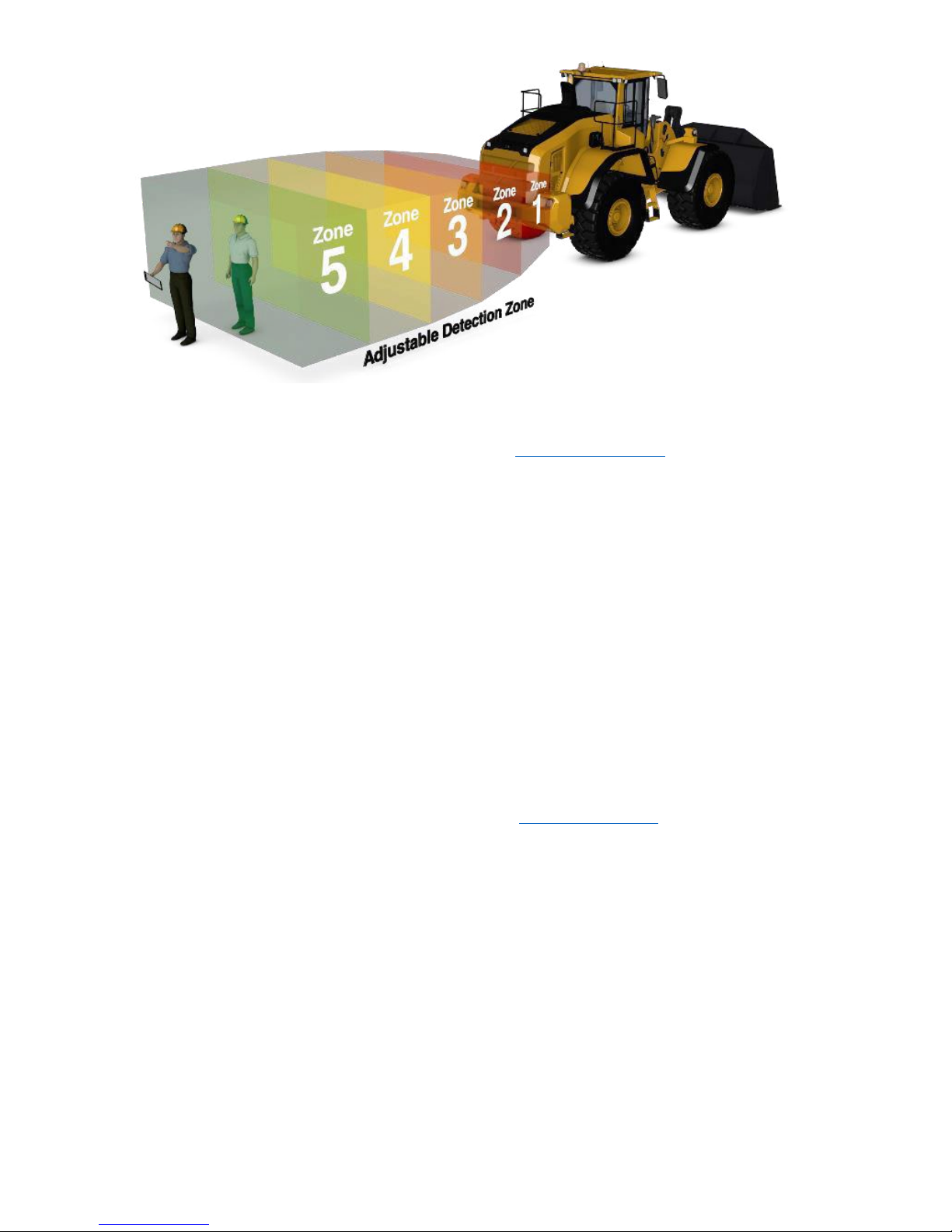
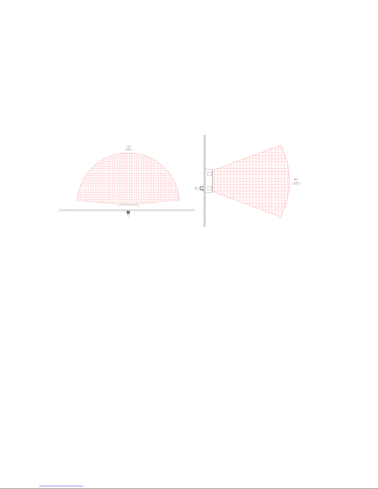
flexibility to be a solution for virtually any application. Figure 2 illustrates
an example of the Sentry™sensor’s adjustable detection zone.
+1.866.977.7326
www.preco.com
3702008A
Copyright 2016
Page 2
Figure 2. Adjustable Detection Zone
The Sentry™has multiple models with preconfigured detection zones: both
range and width of detection zone. Note: the www.preco.com website
contains the most current data on radar sensor models.
Sentry™ST87 Series radar sensors include an 8-pin Deutsch connector
pigtail as shown in Figure 1. The Sentry™ST82 Series radar sensors use
an 8-pin Conxall connector on the back of the radar.
The Sentry™model numbering system is as follows:
Model ST8XYYZ, where:
X defines the connector type - 7 is for Deutsch and 2 is for
Conxall
YY defines the sensor’s detection range in meters
Z defines the detection width in meters
Example: Model ST87063 describes a sensor with a
Deutsch connector, a 20 feet (6 m) detection range and a
10 foot (3 m) detection width.
Please contact PRECO Electronics®or refer to www.preco.com for available
model numbers.
Tel: +386 3 4900 800
http://radar-electronics.com/
3702008A
Copyright 2016
Page 3
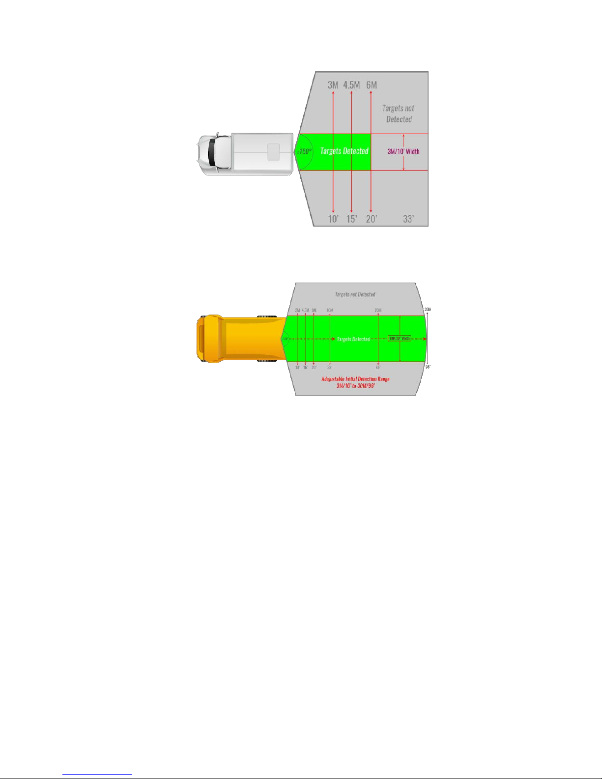
Figure 3 illustrates a truck backing application with the radar detection
zone set to a range of 6 m and a width of 3 m.
Figure 3. Detection Zone 6 m
Figure 4 illustrates a mining haul truck backing application with the radar
detection zone set to a range of 30 m and a width of 10 m.
Figure 4. Detection Zone 30 m
The sensor is active and starts reporting detections within 300
milliseconds (ms) after power up.
The Sentry™performance is not affected by other PreView®Sentry™or
similar sensors operating in close proximity with each other.
Other Sensor Features
The Sentry™sensor has a continuous Built-In-Self-Test (BIST) that notifies
the operator display of sensor failure within a fraction of a second. This
test functions by monitoring the transmit and receive performance as well
as other internal operations.
The Sentry™sensor can also determine if the face of the sensor is blocked
with excessive ice, mud, or snow that is impeding proper operation. This
blockage is then reported to the operator display.
Both the self-test and blockage detection features are important to fail-
safe operation.

+1.866.977.7326
www.preco.com
3702008A
Copyright 2016
Page 4
Sensor Interfaces and Configuration
Communication
The Sentry™communicates with the operator display using a CAN interface
as specified in ISO 11898-2. The CAN bus operates at 250 KBits/second
and is not terminated in the sensor.
Since CAN is a standard communication interface, the sensor can be
connected to other CAN controllers, telematics interfaces, displays, etc.
For custom installations, the CAN bus protocol is available from PRECO®
Electronics. However, it is not described in this document.
Alarm Output
The Sentry™provides an auxiliary output that becomes active whenever the
Sentry™detects an object. This output can be used to activate an external
backup alarm or other devices as desired. The output is switched from a
high impedance state to ground when active and is protected against an
over-current or electrical short condition. The maximum operating current
is approximately 1 amp, including any inrush current.
Sensor Input
The PreView®Sentry™ST87 series radar sensor provides an auxiliary input
that can be used to activate the alarm output, if configured. Contact
PRECO Electronics®for more information.
Cable Connection
The Sentry™comes equipped with a pigtail harness terminated with either
a Deutsch DT connector (ST87 series) or a Conxall Connector (ST82
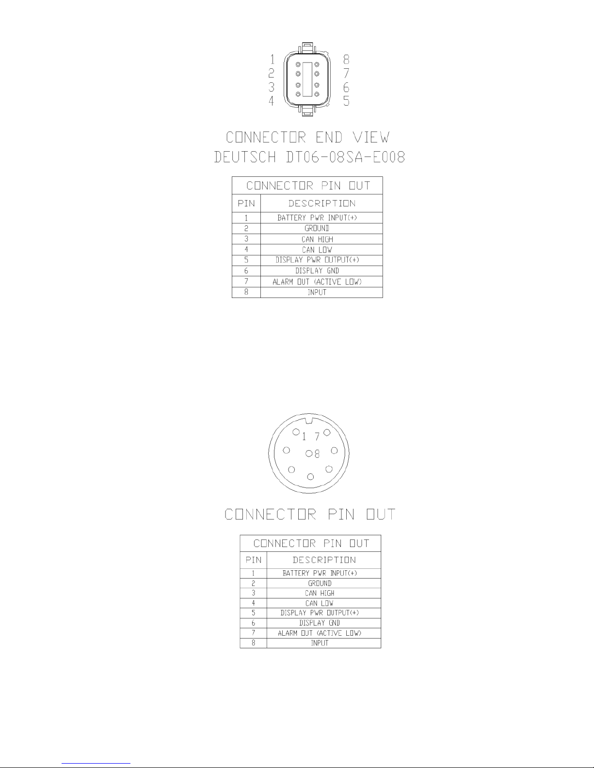
Series). The pinout for the Deutsch connector is defined in Figure 5. The
mate for the Deutsch connector is the Deutsch DT04-08PA-C015.
Tel: +386 3 4900 800
http://radar-electronics.com/
3702008A
Copyright 2016
Page 5
Figure 5. Deutsch Connector Pin Out (ST87 Series)
Figure 6 shows the pin out for the Conxall connector (ST82 Series). The
mate for the Conxall connector is the 6280-8SG-XXX.
Figure 6. Conxall Connector Pin Out (ST82 Series).
+1.866.977.7326
www.preco.com
3702008A
Copyright 2016
Page 6
PRECO Electronics®provides a variety of different cable lengths and
configurations for the PreView®Sentry™radar sensor, as well as solution
kits of radar, cabling, and displays. Please contact PRECO Electronics®for
a list of available cables and kits.
Technical Data
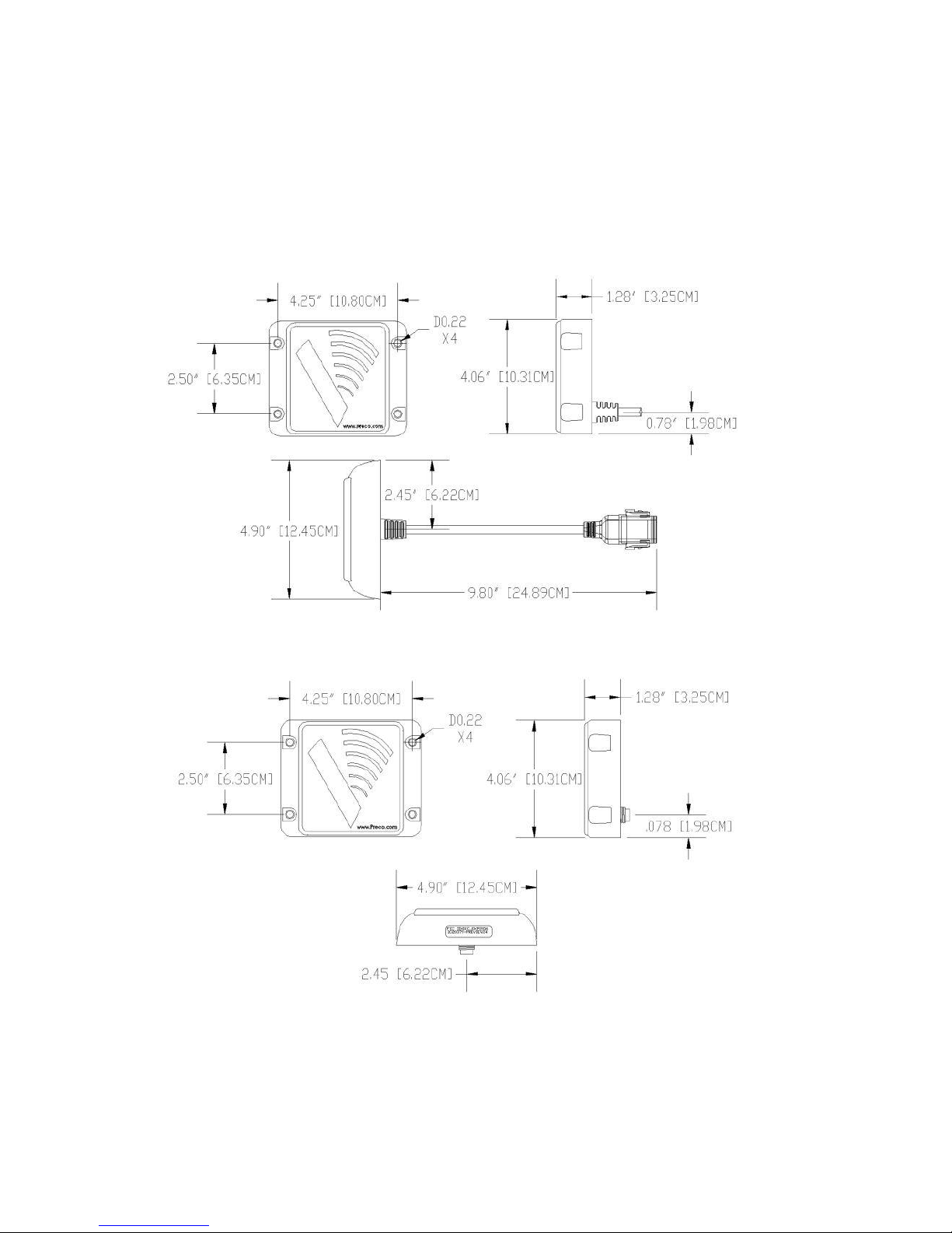
The following figures provide the dimensions and specifications for the
PreView®Sentry™radar sensor.
Figure 7. Sentry™Dimensions (ST87 Series)
Figure 8. Sentry™Dimensions (ST82 Series)

Tel: +386 3 4900 800
http://radar-electronics.com/
3702008A
Copyright 2016
Page 7
Measuring Performance
Range:
0 –30 m (10 dBsm target) depending on model
number
Range Accuracy: 0.3 m
Azimuth Field of View: ±75 degrees (10 dBsm target)
Elevation Field of View: ±10 degrees (10 dBsm target)
Angle Accuracy: ±2° @ ±10° FOV, ±5 @ ±30° FOV, ±10 @ ±75°
FOV
Velocity Range: ±9 m/sec (± 20 mph)
Velocity Accuracy: 0.2 m/sec (0.5 mph)
Target Resolution: 1.4 m for static targets, approaching 0.3 m for
dynamic targets
Cycle Time: 120 ms (A CAN bus target message is provided in
every cycle.)
Operating Conditions
Frequency:
24.00 –24.25 GHz
Power Supply: 9 –33 VDC, Reverse polarity and over-voltage
protected
Current:
<0.5 A
Operating Temperature:-40°C to +85°C
Storage Temperature: -55°C to +105°C
Shock:
50 G
Vibration:
25 G, random, all three axis
Protection Rating: IP69K
Operating Modes
Detection Pattern: Fixed based on model number
Target Detection Time: 300 ms
Power On to Active Time: 300 ms
Communications Interface
J1939 CAN Bus: 250 Kbits/sec, not terminated
LED Interface Switch to ground, sink up to 1A, over current
protected
Physical Characteristics
Sealing:
IP69K
Housing Material: Polycarbonate radome
Dimensions:
4.90” (w) x 4.06” (h) x 1.28” (d) (12.4 cm x 10.3
cm x 3.25 cm)
Weight:
1.0 lb (0.45 kg).
Mounting:
Four 0.22" (5.6 mm) diameter mounting holes.
Figure 9. Sensor Specifications

+1.866.977.7326
www.preco.com
3702008A
Copyright 2016
Page 8
Regulatory Compliance
The Sentry™is compliant with the following countries/regions and their
regulations as of the published date of this manual. The sensor may be
compliant in other countries/regions. Please check your local regulations.
United States - FCC- Part 15.249
o
FCCID: OXZJCKP2016
Canada - RSS-210 Radio Standards Specification
European Union - ETSI EN300 440-1 Electromagnetic
Compatibility and Radio Spectrum Matters (ERM)
Australia/New Zealand - AS/NZ 4268 Radio Equipment and
Services –Short Range Devices

Tel: +386 3 4900 800
http://radar-electronics.com/
3702008A
Copyright 2016
Page 9
Installation
Sensor Mounting
The Sentry™mounting location is important for proper system operation.
Ideally the sensor should be mounted on the rear of the vehicle as close to
the center as possible at roughly 36” (1 m) above the ground. The sensor
face should be perpendicular to the ground with the small end of the “V”
graphic on the sensor face pointing down. Select a location that will
provide some protection from impact and debris while allowing an
unobstructed view of the target hazard area. Refer to the Keep
Out/Interference Zones listed in Figure 11.
Mounting Tolerances
Mounting height tolerance at 36” (1 m) should be within +/- 12” (0.3 m).
For optimal performance at 36” (1 m), the vertical angle (Up/Down)
tolerances are +5 degrees (up) and -2 degrees (down), and the horizontal
angle tolerance is +/- 5 degrees.
Figure 10. Vertical and Horizontal Angle Mounting Tolerances
Exceptions: if mounting higher than 4 feet (1.3 m), the sensor can be
angled down a few degrees as necessary (less than 5 degrees in most
applications).
Tel: +386 3 4900 800
http://radar-electronics.com/
3702008A
Copyright 2016
Page 11
The performance of the sensor can be negatively impacted if the sensor is
angled down, causing false detection from the ground. Any time the
sensor is not perpendicular to the ground, the performance should be
tested. In some instances, mainly with longer range models, the sensor
may need to be angled upward to reduce false detections from the ground.
Keep Out/Interference Zones
Metallic and any other strong radar reflecting objects must remain outside
of the keep out zones defined in Figure 11. If radar reflecting objects
reside within the keep out zones, testing must be performed to determine
their influence on the sensor’s performance.
Horizontal “Keep Out” Zone Vertical “Keep Out” Zone
Figure 11. Keep Out Zones
The sensor’s horizontal field of view is +/- 75 degrees and the vertical field
of view is +/- 10 degrees. For optimal performance, the sensor should
protrude beyond any other portion of the vehicle.
Important!
Before permanently installing the Sentry™on the vehicle, verify that the
selected sensor mounting location provides a clear detection zone. Take
the machine to a clear area, temporarily attach the sensor in the proposed
mounting location, apply power to the system, and verify that nothing is
being detected.
Sensor Mounting Procedure
PRECO Electronics®supplies two different brackets for the Sentry™radar
sensor. If the provided 90° bracket shown in Figure 12 is not appropriate,
an adjustable mounting bracket is available, shown in Figure 13.

Tel: +386 3 4900 800
http://radar-electronics.com
3702008A
Copyright 2016
Page 10
Figure 12. Provided SD-BK90 (90° Mounting Bracket)
If mounting to the vehicle using the provided bracket, follow the procedure
outlined below.
1.
Select the appropriate sensor mounting location.
2.
The standard mounting configuration is with the small end of the “V”
graphic pointing down, as shown below.
3.
Using the provided bracket as a drill template, scribe position marks
through the holes. Drill 1/4” (6 mm) holes centered at the marks.
4.
If needed, a 1.5” (40 mm) diameter clearance hole is required for the
sensor connector and mating cable connector.
5.
Secure the sensor to the bracket with the four supplied #10-24 UNC
button head screws, washers, and locking nuts or equivalent. Apply a
maximum torque of 22 lb-inch (25 kg-cm) when securing the sensor.
Figure 13. ST-ASB (Adjustable Mounting Bracket)

Tel: +386 3 4900 800
http://radar-electronics.com/
3702008A
Copyright 2016
Page 12
Troubleshooting
The troubleshooting below is for the most common PreView®display.
Refer to the particular display manual for errors code descriptions.
Display Status LED is not illuminated.
Verify that DC power (9-33 V) is applied to the sensor.
Verify that the cable between the sensor and display is connected.
Display Status LED is RED.
Check connection between display and sensor.
Display Status LED is RED and one Yellow LED is illuminated.
LED Error Code
Possible Reason
LED #5 on
No communication with any sensor(s)
LED #4 on
Built in Self-Test Error –Contact Factory
LED #3 on
Missing sensor(s)
Display Status LED is RED and all yellow LEDs are illuminated.
A sensor blockage indication - verify that the sensor face is clean.
All the display LEDs are illuminated when sensor is mounted.
Verify the sensor is pointing outward from the vehicle in an open area
with no obstructions. This may require removing the mounting screws
and lifting the sensor out and away from the rear of the vehicle. If the
display LEDs are not active when moved away from the vehicle, but
are active when mounted, then the sensor’s mounting position will
have to be moved.
Sensor is detecting the ground, indicated by a few of the display LED’s
being lit.
In an open field, either move the sensor up higher or slightly angle the
sensor upward 2 to 5 degrees. The minimum recommended mounting
height is 24 inches.

Tel: +386 3 4900 800
http://radar-electronics.com/
3702008A
Copyright 2016
Page 13
Object Detection Capability
The PreView®Sentry™system is a blind spot collision warning system
designed to supplement other safety practices and/or devices. The
machine operator is always the first line of defense when safely operating
a vehicle. The person or owner responsible for the equipment must ensure
that all operators understand the installation, operation, limitations and
safe use of the system.
The Sentry™can detect most objects within the detection zone. However,
there are some instances where objects can go undetected. Obstacle size,
shape, relative location, and composition are all factors determining if,
when, and where an object is detected. The Sentry™operates by
transmitting low power electromagnetic energy. Any energy that strikes an
object reflects a certain amount of this energy back to the PreView®
Sentry™radar sensor. If the returned energy is of sufficient magnitude, it is
used to indicate object presence and determine the object’s distance.
While the Sentry™can resolve multiple objects, only the object closest to
the vehicle is reported to the operator display since it represents the most
significant collision threat.
The amount of energy returned is based on a few factors:
Size –a larger object usually reflects more energy than a smaller
object.
Composition –a metal object typically reflects more energy than a
non-metallic object.
Scattering –a solid object reflects more energy than a non-solid
object such as tree branches, gravel, bushes, etc.
Shape –complex shapes cause energy to be returned in a very
non-uniform way. Very small variations or movement can change
detection status.
Angle –an object flat side perpendicular to the sensor will reflect
more energy than an object at an angle. See Figure 14 for an
example of how angle can affect return energy.

Tel: +386 3 4900 800
http://radar-electronics.com/
3702008A
Copyright 2016
Page 14
Figure 14. Object Reflection

Tel: +386 3 4900 800
http://radar-electronics.com/
3702008A
Copyright 2016
Page 15
Notes on Safety and Risks
Owner Responsibilities
The owner is responsible for ensuring that the device (and equipment) are
used for their intended purpose, for the actions of the employees, for
giving instruction to the employees, and for the operational safety of the
equipment. The owner must understand the safety information for the
device and the instructions given in the operating manual.
Lacking or incomplete training can lead to incorrect operation or improper
usage. This may result in accidents involving serious injury or damage to
property, assets, or the environment.
Always make sure that the device or equipment is not operated, serviced,
or used by personnel who have not been properly trained to do so.

Tel: +386 3 4900 800
http://radar-electronics.com/
3702008A
Copyright 2016
Page 16
PreView®Sentry™Daily Maintenance
Detach this page and place with daily operator maintenance procedures.
Safety Message to Operators of Vehicles with PreView®Sentry™Systems
1. The PreView®Sentry™system is intended as an Object Detection System and
should not be relied upon as your first line of defense for the safe operation of
the vehicle. It should be used in conjunction with established safety programs
and procedures to augment the safe operation of the vehicle, ground
personnel, and adjacent property. Should the system become inoperative, it
could jeopardize the safety or lives of those who depend on the system for
safety.
2. Testing and inspection of the system in accordance with these instructions
and a record of the results should be listed on the daily maintenance report.
The units on operating vehicles must be tested each day prior to the vehicle's
operation. Results of this test must be recorded in the maintenance log.
3. People operating this equipment MUST check for proper operation at the
beginning of every shift or safety inspection period.
4. If a PreView®system is found to be inoperative upon test, the operator should
flag or cover the driver display and mark as “inoperative” prior to the
machine/vehicle operation.
5. People's lives depend on the proper installation of this product in conformance
with these instructions. It is necessary to read, understand, and follow all
instructions shipped with the product.
6. Failure to follow all safety precautions and instructions may result in property
damage, serious injury, or death.
7. The PreView®Sentry™is intended for commercial use. Proper installation
requires a good understanding of vehicle/machine electrical systems and
procedures, along with proficiency in the installation.
8. Store these instructions in a safe place and refer to them when maintaining
and/or reinstalling the product.
Testing and Maintenance
NOTE: A walk-around test shall be performed every day to verify proper function of
the system and to familiarize the operator with the zone of detection. More
frequent inspections should be performed when:
The vehicle is operating in a particularly dirty or harsh environment.
The operator has reason to suspect the system has been damaged.
This test should be performed with two people, one who remains in the cab (the
operator), and one who walks through the sensor detection field (the assistant).
The below example illustrates the test for a backing sensor application. Use a
similar procedure for front, side or multiple radar systems by confirming detection
of each radar sensor in the operator display.
1. Clean the sensor face of any accumulation of dirt, mud, snow, ice, or debris.
2. Visually inspect the attached wiring and cable and verify that they are properly
secured, not chafing or dangling free where they could become snagged and
damaged. Inspect the Radar Sensor and Operator Display Module and verify
that they are securely attached to the vehicle.
This manual suits for next models
1
Table of contents


