Prima FIT I User manual

13615 Marquardt Ave. Santa Fe Springs, CA 90670
Ph. 562-407-3079 . Fx. 562-407-3069
www.primalighting.com
IMPORTANT!:
• Please refer to the Prima catalog for proper lamp type & max. wattage.
• Prima is not responsible for any fixture or system failure caused by lamps not supplied by Prima.
• Always contact Prima customer service for the latest updates on the proper use of the lamps.
• A specified transformer from Prima is needed for the low voltage FIT I System installations.
• Prima Lighting will not warrant the fixtures or systems if Prima transformers are not used.
• The Prima Lighting catalog provides general suggestions as to the proper style of dimmer switch.
However, always consult Prima customer service for the use of any specific dimmer.
• Prima Lighting is not responsible for any fixtures damaged or system malfunctions caused
• This track system is not intended for use with a power supply cord or convenience receptacle adapter.
by the incompatibility of non-specified or suggested dimmers.
REV.033015
PRIMA LIGHTING - FIT I SYSTEM
IMPORTANT SAFETY INSTRUCTIONS
IF YOU HAVE ANY QUESTIONS REGARDING THE INSTALLATION OF
THIS PRODUCT, PLEASE CALL PRIMA CUSTOMER SERVICE AT
1-562-407-3079
INSTALLATION INSTRUCTION
A) READ ALL OF THESE INSTALLATION INSTRUCTIONS BEFORE INSTALLING THE FIT I
SYSTEM.
B) DO NOT INSTALL THIS SYSTEM IN DAMP OR WET LOCATIONS.
C) DO NOT INSTALL THIS SYSTEM OR ANY PART WHICH CONTAINS EXPOSED
WIRES LESS THAN 7 FEET FROM THE FLOOR.
D) DO NOT INSTALL ANY LUMINAIRE ASSEMBLY CLOSER THAN 6 INCHES FROM
ANY CURTAINS OR SIMILAR COMBUSTIBLE MATERIAL.
E) DISCONNECT ELECTRICAL POWER BEFORE ADDING TO OR CHANGING THE
CONFIGURATION OF THE TRACK.
F) DO NOT ATTEMPT TO ENERGIZE ANYTHING OTHER THAN LIGHTING TRACK
LUMINAIRES ON THE TRACK. TO REDUCE THE RISK OF FIRE AND ELECTRIC
SHOCK, DO NOT ATTEMPT TO CONNECT POWER TOOLS, EXTENSION CORDS,
APPLIANCES, AND THE LIKE TO THE TRACK.
G) DO NOT CONNECT A TRACK TO MORE THAN ONE BRANCH CIRCUIT UNLESS
THE TRACK IS CONSTRUCTED SO THAT IT CAN BE USED WITH MORE THAN
ONE BRANCH CIRCUIT. CHECK WITH A QUALIFIED ELECTRICIAN.
SAVE THESE INSTRUCTIONS AND REFER TO THEM WHEN ADDITIONS
TO OR CHANGES IN THE TRACK CONFIGURATION ARE MADE. THESE
INSTRUCTIONS CONTAIN IMPORTANT INFORMATION REGARDING
YOUR NEW PRIMA LIGHTING FIXTURES.

PRIMA LIGHTING - FIT I INSTALLATION MANUAL
CAUTION
1. Failure to properly install low voltage electrical products may void the warranty. Please ensure the proper
electrical connections as follows:
• Follow instruction guidelines when wiring and installing transformers.
•Firmly connect the transformer’s secondary leads to the FIT I System track as described in the power
feed instruction sheets. ting connections at all conductive
•Be sure the lamp is firmly seated in the socket.
•Check to ensure that no wires, cables or packing materials are crossing both conductors of the
FIT I track.
2. Make sure all power connections are tight. Follow this procedure to ensure proper connection:
• Read all transformer instruction sheets before installation.
• Turn on the power only after system installation is complete.
• 60 minutes after power-up, check for excess heat at power connection areas.
• Tighten any connections that feel hot and assure to use 10 AWG THHN single standard wire from
transformer to powerfeed. The use of this wire is to maintain the standard 25 amp capacity.
• Do not use Romex cable or MC rigid cable for secondary wire connections.
•For long distance remote connections, please refer to the voltage drop table in the back of this
instruction manual.
3. Measure voltage after the installation is complete. Secondary voltage for 12V system should be between 11.3V
to 11.7V with 85% to 90% load without dimmer, and for 24V system should be between 22.6V to 23.4V
Since electronic transformers run at a higher frequency, the use of a high-end voltage meter such as
Fluke 87 is recommended.
4.Always turn off the power and allow the system to cool before attempting any adjustments such as moving
powerfeeds, adjusting pendant cable lengths, moving trackheads or changing light bulbs.
5. Prima Lighting includes lamps for each fixture we ship. The lamps included are top quality and well-
known name brands. We will normally send 50W MR16 for spotlights and 50W Xelogen G6.35 lamp for
pendants unless otherwise specified differently in the catalog. Prima will also ship according to customers’
specific lamp type or wattage per order. Lamps are complimentary, thus we will not offer free replacement,
nor will we issue any credit for lamps. However, customers may purchase lamps from us and receive standard
lamp warranty. We always encourage our customers to purchase replacement lamps directly from us
when replacements are needed.
6. If systems are ordered without transformers, all warranties are void and complimentary lamps will not be
supplied.
11.If you experience problems or irregular function of the system, stop the installation immediately and contact
Prima Lighting Customer Service for assistance.
13615 Marquardt Ave. Santa Fe Springs, CA 90670
Ph. 562-407-3079 . Fx. 562-407-3069
www.primalighting.com
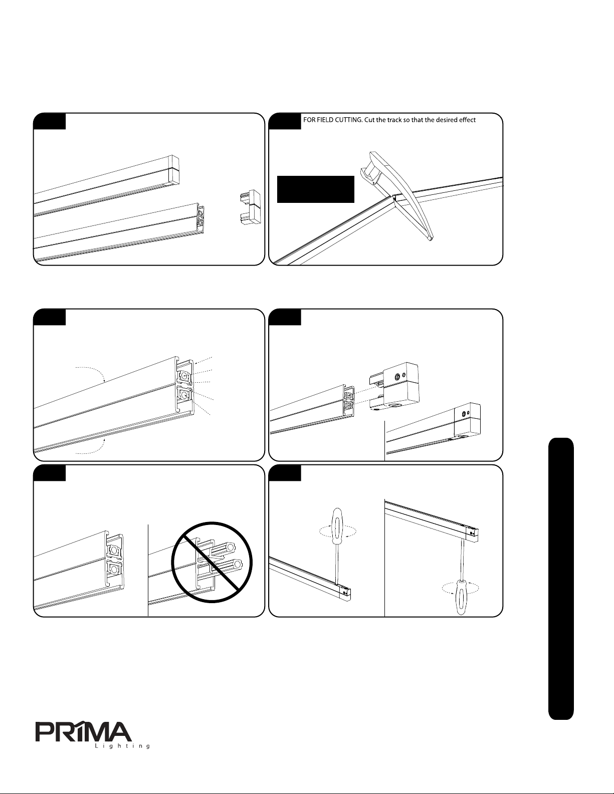
FIT I interconnecting joints.
with 85% to 90% load without dimmer. Magnetic transformers may be tested with most voltage meters.
7. The maximum permissible load allowed on any Prima Rail circuit is 25 amps. The rail can be operated at 12 volts
with a 300W maximum load or at 24 volts with a 600W maximum load.
8.
9. When cleaning FIT I System track, be sure to use a clean damp cotton cloth.
Prima Lighting systems are listed by ETL. Our system products are only listed when used as a complete system. All
components, including transformers, must be provided by Prima Lighting. The substitution of Prima products with
another manufacturer’s product will render the listing completely void. Prima Lighting is removed from liability
and any insurance to which you may be entitled will be jeopardized.
Questions or problems you can’t find answered here? Call 1-562-407-3079 during regular business hours
(Monday-Friday 7:00-4:00pm PST).
CAUTION! Bulbs, metal, and other parts of elements may become hot. Use protective gloves and adjust
elements by their coated handles and cords.
REV. 033015
10. Do not apply any paint material over our tracks and connectors.

13615 Marquardt Ave. Santa Fe Springs, CA 90670
Ph. 562-407-3079 . Fx. 562-407-3069
www.primalighting.com
If your system does not turn on:
•ALWAYS check the fuse or thermal breaker first. Fuses and breakers are easily replaced and can be bought from any
local electrical distributor or directly from Prima Lighting. BYPASSING A FUSE OR THERMAL BREAKER CAN RESULT IN FIRE!!
• Check all switches and breakers, including the main panel breaker and the breaker button on the transformer.
•Make sure all wire connections and piercing contacts are tight and well connected (transformer to conductor leads,
junction box, connectors between rails).
• Check the output side of the transformer with a multimeter and make sure the power is there.
• Check that the bulbs and sockets are installed securely and are not burned out.
•The system will shut down if it is overloaded. Make sure that the total wattage of the lamp elements does not exceed
the transformer’s maximum wattage rating.
•The system will shut down if there is a short. Make sure that the rail and elements are not coming in contact with any
other metal surfaces and that each element is installed properly.
Common Troubleshooting on TRANSFORMER and BREAKERS
If the breaker at the transformer is tripping, please follow these troubleshooting steps:
1. Remove all lighting elements and reset the breaker.
2. Attempt to turn the system on.
If the system still trips, look inside the transformer housing and make sure all connections are secure and that there is no
short. If the system stays on, you most likely have a problem with one of the lighting elements. Re-install one element at
a time and check if the system works to find the defective element. Ensure that the lighting socket is okay, wires are not
stripped or shorted, and the lamps are within the allowed wattage.
If the breaker at the main panel keeps tripping when the system is first turned on, you may need to replace this
breaker with an inductive breaker, or you may have a short on the 120 volt side of the transformer.
Nuisance Tripping
Sometimes, for no apparent reason, the secondary circuit breakers on the transformers will trip. Some things to consider:
1. Allow a 20% safety factor in estimating your load wattage. The bulbs often carry a load of up to 5% more than
specified, wire length, gauge, and connection variation may impact the actual load. Using proper wire nuts and
ensuring wires have 1/2” long contacts length are essential to minimize loading.
by your local electrical codes (use the 20% safety factor as mentioned above), and all transformers should be mounted
as designed.
3. If using a dimmer, use a compatible low-voltage dimmer only.
If using remote magnetic transformer, the transformer has to be mounted vertically with the breakers facing downward
for better heat dissipation.
REV.033015

fit I system track installation prep
Follow all local and national electrical codes.
For assistance please call Prima Customer Service at 562-407-3079
A1 A2
IMPORTANT Please read these instructions prior to installation. Refer to the Prima catalog for proper lamp type and maximum wattage for fixtures.
Prima is not responsible for any fixture or system failure caused by unsupported lamps. Contact Prima customer service for the latest updates on
which lamps we support and proper usage. Prima low voltage transformers must be used with all Prima Lighting product installations. All warranties
are void if Prima transformers are not used. Prima’s catalogs provide general information and suggestions for proper dimmer usage. Please consult
our customer service department with any questions regarding dimmer specifics. Prima is not responsible for any damage caused by improper
dimmer specification and usage. Use only qualified electrician for installation. Adhere to all local and national electrical codes prior to installation.
It is strongly recommended that gloves are used when handling the FIT I System track. Oils and dirt from fingers can sometimes permanently
mark the finish. Track should be cleaned with a damp cloth and thoroughly dried before fixture installation.
Determine whether the FIT I track length will be installed as
part of a series of connected track lengths or as a single
stand alone track length. Before attempting to field cut the FIT I track,
ensure that the end caps are firmly installed into both ends. If an end
cap has become loose during shippping, replace it.
and lengths can be achieved. FIT track may be field cut with
an ordinary hacksaw. Be sure to use a FINE-TOOTH METAL CUTTING
BLADE. Be sure to deburr and clean all cuts prior to final assembly.
fit I system track connector/powerfeed basics
B1 B2
Connectors are available for extending track length, turning corners or creating intersections in the run. Great care must be taken to ensure
the connector is installed properly.
FIT I track is constructed of an aluminum housing which
doubles as the neutral conductor. Each of the two slots of the
track include one conductor and one insulator. The slots may used as
two separate circuits with the proper use of powerfeeds. The track may
also be configured as one circuit for both slots with the use of a jumper.
When installing a connector or powerfeed, place the opposite
end of the track length against a solid flat surface to keep the
internal parts of the track from sliding. Carefully align the connector pins
on the connector with the holes in the track’s conductors. Insert the
connector all the way into the track until it stops.
Track housing/
Neutral
Conductor 1
Insulator 1
Slot 1
Slot 2
Conductor 2
Insulator 2
B3 B4
When installing a connector at the end of a FIT I track length,
great care should be taken to ensure the connector is properly
installed. After the connector has been inserted into the end of the track,
inspect the opposite end of the track. If the inslulators and conductors
are flush with the end, then the installation was successful. If the
conductors protrude past the end of the track AT ALL then connector is
not properly installed.
When the connector or powerfeed is properly inserted into the
track length, secure the installation by tightenting the lock
screws located at the top and bottom of connector. DO NOT
OVERTIGHTEN THE SCREWS.
Opposite end after a
proper connector installation.
Opposite end after an
improper connector installation.
FIT SYSTEM TRACK
MAY NOT BE BENT IN
ANY WAY
FIT I System track
may not be bent
13615 Marquardt Ave.Santa Fe Springs, CA 90670
Ph. 562-407-3079 . Fx. 562-407-3069
www.primalighting.com
*Caution:
Do not break the insulator inside
the chamber while using the
screw-in function. Broken insulator
will cause short of circuit.
*Caution
REV.033015
prima fit I system
general installation instructions part 1 of 12

C
IMPORTANT Please read these instructions prior to installation. Refer to the Prima catalog for proper lamp type and maximum wattage for fixtures.
Prima is not responsible for any fixture or system failure caused by unsupported lamps. Contact Prima customer service for the latest updates on
which lamps we support and proper usage. Prima low voltage transformers must be used with all Prima Lighting product installations. All warranties
are void if Prima transformers are not used. Prima’s catalogs provide general information and suggestions for proper dimmer usage. Please consult
our customer service department with any questions regarding dimmer specifics. Prima is not responsible for any damage caused by improper
dimmer specification and usage. Use only qualified electrician for installation. Adhere to all local and national electrical codes prior to installation.
It is strongly recommended that gloves are used when handling the FIT I System track. Oils and dirt from fingers can sometimes permanently
mark the finish. Track should be cleaned with a damp cloth and thoroughly dried before fixture installation.
FIT I System adapter are installed in the track using a twist-and-lock method. The adapter is inserted at the desired location on the track
length. Pressure is applied on the adapter to compress the internal contact/pressure mechanism. While applying said pressure, the
adapter is rotated 90º clockwise until it stops. To secure the adapter, the knurled locking ring is rotated clockwise by hand until sufficient pressure
creates a solid and secure mounting. IMPORTANT: Do not attempt to slide the adapter to other locations on the track length after it is installed. The
adapter must be completely removed from the track slot and reinstalled at the new location.
Insert the adapter into the
track slot
Apply pressure and
rotate 90º clockwise After rotation,
adapter rests
inside track slot.
Rotate knurled
locking ring
clockwise to
secure the adapter.
There should now
be a gap between
the two knobs.
C1
D1 D2 D3 D4 D5
C2 C3 C4 C5
Ensure that there is
no gap between
the knurled knobs
before installation.
Rotate knurled
locking ring
clockwise to
secure the adapter.
There should now
be a gap between
the two knobs.
Ensure that there is
no gap between
the knurled knobs
before installation.
FIT I SYSTEM TRACK REQUIRES SUPPORT POINTS BE INSTALLED EVERY 4’
D
l mounted
support. The following steps cover the general task of inserting the support adapter into the track slot. See the individual steps for various
support method installation instructions. It is strongly recommended that gloves are used when handling the FIT I System track. Oils and dirt
from fingers can sometimes permanently mark the finish. Track should be cleaned with a damp cloth and thoroughly dried before fixture
installation.
FIT I System support adapters are installed in the track using a twist-and-lock method. The support adapter is inserted at the desired
location on the track length. The adapter is rotated 90º clockwise until it stops. With a stem suspended support adapter, it will be
necessary to SLIGHTLY loosen the stem coupler to allow the adapter to rotate and lock into the track slot. To secure the adapter, the knurled
locking ring is rotated clockwise by hand until sufficient pressure creates a solid and secure mounting. IMPORTANT: Do not attempt to slide the
adapter to other locations on the track length after it is installed. The adapter must be completely removed from the track slot and reinstalled at the
new location.
Insert the support adapter
into the track slot
Loosen the set screw with
the supplied hex wrench.
(for stem only)
Rotate the adapter 90º
until the track rests on
the adapter.
Tighten the set screw
with the hex wrench.
(for stem only)
fit I system fixture adapter installation
Follow all local and national electrical codes.
For assistance please call Prima Customer Service at 562-407-3079
fit I system vertical support adapter installation
13615 Marquardt Ave.Santa Fe Springs, CA 90670
Ph. 562-407-3079 . Fx. 562-407-3069
www.primalighting.com
Black top knob is for
locking purposes.
Hold the bottom knob with
your fingers. Do not use a
plier or any other tools that
will hurt the adapter and finish.
REV.033015
C
D
prima fit I system
general installation instructions part 2 of 12

fit I system support for horizontally oriented track
for cable suppport
Follow all local and national electrical codes.
For assistance please call Prima Customer Service at 562-407-3079
E
E1 E2 E3
E4 E5 E6 E7
IMPORTANT Please read these instructions prior to installation. Refer to the Prima catalog for proper lamp type and maximum wattage for fixtures.
Prima is not responsible for any fixture or system failure caused by unsupported lamps. Contact Prima customer service for the latest updates on
which lamps we support and proper usage. Prima low voltage transformers must be used with all Prima Lighting product installations. All warranties
are void if Prima transformers are not used. Prima’s catalogs provide general information and suggestions for proper dimmer usage. Please consult
our customer service department with any questions regarding dimmer specifics. Prima is not responsible for any damage caused by improper
dimmer specification and usage. Use only qualified electrician for installation. Adhere to all local and national electrical codes prior to installation.
It is strongly recommended that gloves are used when handling the FIT I track. Oils and dirt from fingers can sometimes permanently
mark the finish. Track should be cleaned with a damp cloth and thoroughly dried before fixture installation.
Be sure that the items indicated below are included in the package. Mount screw anchors in the mounting surface so that they align with
the holes in the mounting disk. Secure the mounting disk to the mounting surface with the included screws. Adjust the cable length by
loosening the set screw on the mounting disk, feed the cable through the top hole and tighten the set screw with the hex wrench. Further
adjustment may be necessary at the end of the installation process. Repeat the steps above for post installation adjustment.
Mounting disk
Hex wrench
Track bracket
Locking knob
Mounting screws
Anchors
If an installation consists of only a single run of FIT I System track mounted in horizontal orientation with cable suspension, it is recommended that
the same amount of track heads be placed in each of the track slots on both sides of the track. This is to balance the weight distribution between
the two track slots. If there is more weight on one side the track than the other, the track may lean to one side and appear out of balance. This
problem will not occur if the track is part of a multi-track length installation with 90º returns.
Insert the track into the
track bracket by resting
the one slot on the grip
teeth. Then twist the track
into position as shown.
This example shows a balanced
installation. The same amount of track
heads are installaed on each side of the
track. The track hangs in a level manner.
Balanced
Balanced
Unbalanced
Unbalanced
This example shows an unbalanced
installation. There is one track installed in
one of the track slots. As a result, the
track installation tends to lean to one side.
Secure the track with the locking knob. Insert the knob into the large hole on the side
of the track bracket. Rotate the track locking knob 90º clockwise to lock the track.
Secure the locking knob by tightening the inner knob until there is no slack and the
Further
adjustment
may be precise
lengths.
90º clockwiseInsert locking knob Tighten inner knob
13615 Marquardt Ave.Santa Fe Springs, CA 90670
Ph. 562-407-3079 . Fx. 562-407-3069
www.primalighting.com REV.033015
prima fit I system
general installation instructions part 3 of 12

fit I system support for horizontally oriented track
for stem suppport
Follow all local and national electrical codes.
For assistance please call Prima Customer Service at 562-407-3079
F1 F2
F3 F4 F5 F6
IMPORTANT Please read these instructions prior to installation. Refer to the Prima catalog for proper lamp type and maximum wattage for fixtures.
Prima is not responsible for any fixture or system failure caused by unsupported lamps. Contact Prima customer service for the latest updates on
which lamps we support and proper usage. Prima low voltage transformers must be used with all Prima Lighting product installations. All warranties
are void if Prima transformers are not used. Prima’s catalogs provide general information and suggestions for proper dimmer usage. Please consult
our customer service department with any questions regarding dimmer specifics. Prima is not responsible for any damage caused by improper
dimmer specification and usage. Use only qualified electrician for installation. Adhere to all local and national electrical codes prior to installation.
It is strongly recommended that gloves are used when handling the FIT I System track. Oils and dirt from fingers can sometimes permanently
mark the finish. Track should be cleaned with a damp cloth and thoroughly dried before fixture installation.
Mounting stem assembly
w/ mounting disk and
track bracket
Locking knob
Mounting
screws
Anchors
FBe sure that the items indicated below are included in the package. Mount screw anchors in the mounting surface so that they align with
the holes in the mounting disk. Secure the mounting disk to the mounting surface with the included screws. Secure the track with the
locking knob. Insert the knob into the large hole on the side of the track bracket. Rotate the track locking knob 90º clockwise to lock the track.
Insert the track into the
track bracket by resting
the one slot on the grip
teeth. Then twist the track
into position as shown. 90º clockwiseInsert locking knob Tighten inner knob
(22-66240 ~ 22-66248)
13615 Marquardt Ave.Santa Fe Springs, CA 90670
Ph. 562-407-3079 . Fx. 562-407-3069
www.primalighting.com REV.033015
prima fit I system
general installation instructions part 4 of 12

fit I system wall support for vertical orientated track only
Follow all local and national electrical codes.
For assistance please call Prima Customer Service at 562-407-3079
G
IMPORTANT Please read these instructions prior to installation. Refer to the Prima catalog for proper lamp type and maximum wattage for fixtures.
Prima is not responsible for any fixture or system failure caused by unsupported lamps. Contact Prima customer service for the latest updates on
which lamps we support and proper usage. Prima low voltage transformers must be used with all Prima Lighting product installations. All warranties
are void if Prima transformers are not used. Prima’s catalogs provide general information and suggestions for proper dimmer usage. Please consult
our customer service department with any questions regarding dimmer specifics. Prima is not responsible for any damage caused by improper
dimmer specification and usage. Use only qualified electrician for installation. Adhere to all local and national electrical codes prior to installation.
It is strongly recommended that gloves are used when handling the FIT I System track. Oils and dirt from fingers can sometimes permanently
mark the finish. Track should be cleaned with a damp cloth and thoroughly dried before fixture installation.
Be sure that the items indicated below are included in the package. Mount screw anchors in the mounting surface so that they align with
the holes in the mounting disks. Secure the mounting disks to the mounting surface with the included screws.
45º
Cable support
mounting disk
should be placed at
a 45º angle from the
end of the stem.
Further
adjustment
may be
necessary for
leveling the
stem.
Hex Wrench
Track locking knob
Mounting Screws & Anchors
Support Stem Assembly
Cable support mounting disk
Insert one end of the support cable into the opening on the cable support mounting disk as shown. Continue to feed the cable through allowing the
cable to pass out the top hole of the cable holder. When sufficient tension is achieved to allow a level stem installation, tighten the set screw on the
cable holder with the hex wrench to lock the support cable in place. Further adjustment may be necessary at the end of the installation process.
Repeat the steps above for post installation adjustment.
Secure the track with the track locking knob. Insert the knob into the large hole on the top of the track bracket. Rotate the track locking knob 90º
clockwise to lock the track. Secure the locking knob by tightening the lower knob until there is no slack and the connection to
90º clockwise
G1
G2
G5 G6 G7
G3 G4
Feed excess cable
through the top hole
Tighten lower knob
Insert the track into the track bracket by resting the bottom slot on the
grip teeth. Then twist the track into position as shown below.
13615 Marquardt Ave.Santa Fe Springs, CA 90670
Ph. 562-407-3079 . Fx. 562-407-3069
www.primalighting.com REV.033015
prima fit I system
general installation instructions part 5 of 12

fit I system picture hanging kits
picture hanging kit I
picture hanging kit II
.sedoclacirtcelelanoitandnalacolllawolloF
9703-704-265taecivreSremotsuCamirPllacesaelpecnatsissaroF
H
a
Insert the top portion of the cable assembly into the slot on the track bracket. Place track bracket onto the pre-mounted FIT I System track
by first catching the grip teeth on the bottom of the bracket on the bottom slot of the track length. Rotate the top portion of the bracket
onto the top slot of the track length. This will capture the top portion of the cable assembly. Secure the track bracket to the track with the track
locking knob. Insert the knob into the large hole on the top of the track bracket. Rotate the track locking knob 90º clockwise to lock the track.
Insert the track adapter into the bottom slot of the FIT I Systemtrack length. Rotate the track adapter 90º clockwise so that it locks into the
slot. Rotate the upper knurled knob of the track adapter clockwise until the adapter forms a snug fit with the track length. Adjust the length
of the support cable with the hex wrench and set screws on the track adapter.
I
Adjust the length of the support cable by
loosening the set screw on the bottom cable
lock. Move the cable lock to the desired
length and push or pull the cable to create a
loop that is approximately 3/8” in diameter.
Tighten the set screw.
Adjust the length of the support cable by
loosening the set screw track adapter and
pushing the cable up and through the exit
hole on the adapter. When the desired length
is achieved, tighten the set screw.
Once properly installed,
the picture hanger kit may
hold up to a 20lb physical
load. ENSURE THAT ALL
KNOBS AND SET
SCREWS ARE
TIGHTENED.
Once properly installed,
the picture hanger kit may
hold up to a 20lb physical
load. ENSURE THAT ALL
KNOBS AND SET
SCREWS ARE
TIGHTENED.
90º clockwise
90º
clockwise
Tighten lower knob
22-79394 cable
Assembly
22-79395 cable
assembly
H1
I1
I5
I7
I6
I2I3I4
H2 H3 H4
H5 H6 H7
H8
H9 H10
H11
Tighten
upper
knob
Multiple support
units may be used
for added stability.
Multiple support
units may be used
for added stability.
22-79240 track bracket is required. A 22-79240
may be ordered specifically for this picture
hanger or an existing 22-79240 on the track
layout may be used. Example: A wall support
uses the same bracket and may serve double
duty to support both the track and the
22-79394 picture hanger kit.
IMPORTANT Please read these instructions prior to installation. Refer to the Prima catalog for proper lamp type and maximum wattage for fixtures.
Prima is not responsible for any fixture or system failure caused by unsupported lamps. Contact Prima customer service for the latest updates on
which lamps we support and proper usage. Prima low voltage transformers must be used with all Prima Lighting product installations. All warranties
are void if Prima transformers are not used. Prima’s catalogs provide general information and suggestions for proper dimmer usage. Please consult
our customer service department with any questions regarding dimmer specifics. Prima is not responsible for any damage caused by improper
dimmer specification and usage. Use only qualified electrician for installation. Adhere to all local and national electrical codes prior to installation.
It is strongly recommended that gloves are used when handling the FIT I System track. Oils and dirt from fingers can sometimes permanently
mark the finish. Track should be cleaned with a damp cloth and thoroughly dried before fixture installation.
13615 Marquardt Ave.Santa Fe Springs, CA 90670
Ph. 562-407-3079 . Fx. 562-407-3069
www.primalighting.com REV.033015
prima fit I system
general installation instructions part 6 of 12

straight connector for horizontally or vertically oriented track
two-tier connectors
T-Bar support connector
Follow all local and national electrical codes.
For assistance please call Prima Customer Service at 562-407-3079
IMPORTANT Please read these instructions prior to installation. Refer to the Prima catalog for proper lamp type and maximum wattage for fixtures.
Prima is not responsible for any fixture or system failure caused by unsupported lamps. Contact Prima customer service for the latest updates on
which lamps we support and proper usage. Prima low voltage transformers must be used with all Prima Lighting product installations. All warranties
are void if Prima transformers are not used. Prima’s catalogs provide general information and suggestions for proper dimmer usage. Please consult
our customer service department with any questions regarding dimmer specifics. Prima is not responsible for any damage caused by improper
dimmer specification and usage. Use only qualified electrician for installation. Adhere to all local and national electrical codes prior to installation.
It is strongly recommended that gloves are used when handling the FIT I System track. Oils and dirt from fingers can sometimes permanently
mark the finish. Track should be cleaned with a damp cloth and thoroughly dried before fixture installation. Connectors are available for
extending track length, turning corners or creating intersections in the run. Great care must be taken to ensure the connector is installed
properly.
JThe Straight Inline connector for horizontal or vertical orientations has the benefit of being virtually undetectable after installation. This
connector does not add any length to the over all track run. Insert the conductive (22-79232) or non-conductive (22-79233) inserts into the
conductor hole on one of the track lengths. Insert the top and bottom cover half way into the same track length and secure by tightening the set
screws with a flat head screwdriver. Connect the second track length and secure by again tightening the set screws with a flat head screw driver.
There should be no space between the connected track lengths after installation is complete.
KTwo tier connectors are for attaching two track length together in a perpendicular formation, one on top of the other. There are two types
of two-tier connector, one which conducts the power circuit (22-79302 conductive) and one which does not (22-79301 non-conductive). Both
connectors install in the same way.
Insert the connector into the two track slots Rotate the knurled knobs on the connector 90º
each to lock into the track slots.
LPrima’s T-Bar support connector allows you to connect a cable or stem support point to a standard T-Bar ceiling structure. The clip simply
twists onto the T-Bar and locks into place. Cable and stem support hardware is sold separately.
90º
90º
Available for stem or cable
support hardware (sold separately)
T-Bar clip lock onto T-Bar ceiling support.
13615 Marquardt Ave.Santa Fe Springs, CA 90670
Ph. 562-407-3079 . Fx. 562-407-3069
www.primalighting.com REV.033015
prima fit I system
general installation instructions part 7 of 12

fit I system connectors
connectors for horizontally oriented track
connectors for vertically oriented track
using support points in vertical connectors
MFIT I system connectors are available in 2, 3 and 4 way versions. The example below demonstrates a three way connector for horizontally
oriented track. It is especially important to ensure that all track lengths are firmly attached to the connector. It is also important to ensure
that during the connector installation process, the track conductors were not push out the opposite side of the track length. This is explained in
detail in Part 1 of this instruction manual. Be sure to tighten all of the lock screws on the connector.
Tighten all of the lock screwsAll track lengths are firmly attached
Track connector for horizontally oriented track
NFIT I system connectors are available in 2, 3 and 4 way versions. The example below demonstrates a three way connector for vertically
oriented track. It is especially important to ensure that all track lengths are firmly attached to the connector. It is also important to ensure
that during the connector installation process, the track conductors were not pushws out the opposite side of the track length. This is explained in detail
in Part 1 of this instruction manual. Be sure to tighten all of the lock screws on the connector.
Tighten all of the lock screws
All track lengths are firmly attached
Track connector for vertically oriented track
Follow all local and national electrical codes.
For assistance please call Prima Customer Service at 562-407-3079
IMPORTANT Please read these instructions prior to installation. Refer to the Prima catalog for proper lamp type and maximum wattage for fixtures.
Prima is not responsible for any fixture or system failure caused by unsupported lamps. Contact Prima customer service for the latest updates on
which lamps we support and proper usage. Prima low voltage transformers must be used with all Prima Lighting product installations. All warranties
are void if Prima transformers are not used. Prima’s catalogs provide general information and suggestions for proper dimmer usage. Please consult
our customer service department with any questions regarding dimmer specifics. Prima is not responsible for any damage caused by improper
dimmer specification and usage. Use only qualified electrician for installation. Adhere to all local and national electrical codes prior to installation.
It is strongly recommended that gloves are used when handling the FIT I System track. Oils and dirt from fingers can sometimes permanently
mark the finish. Track should be cleaned with a damp cloth and thoroughly dried before fixture installation.Connectors are available for
extending track length, turning corners or creating intersections in the run. Great care must be taken to ensure the connector is installed
properly.
OFIT I System connectors for vertically oriented track have the capability to accept cable or stem ceiling support point. By removing the axis
cap with a flat head screwdriver, a threaded hole is exposed at the center of the connector. Thread the track adapter portion of the
support point into this hole. Secure the support point to the connector by tightening the lower knob on the adapter.
Use a flat head screwdriver to remove the axis cap at the center of the connector Thread the support point
into the hole at the
center of the connector
13615 Marquardt Ave.Santa Fe Springs, CA 90670
Ph. 562-407-3079 . Fx. 562-407-3069
www.primalighting.com
*Caution
*Caution:
Do not break the insulator inside
the chamber while using the
screw-in function. Broken insulator
will cause short of circuit. This applies to 2, 3, and 4 way connectors. REV.033015
prima fit I system
general installation instructions part 8 of 12

Follow all local and national electrical codes.
For assistance please call Prima Customer Service at 562-407-3079
IMPORTANT Please read these instructions prior to installation. Refer to the Prima catalog for proper lamp type and maximum wattage for fixtures.
Prima is not responsible for any fixture or system failure caused by unsupported lamps. Contact Prima customer service for the latest updates on
which lamps we support and proper usage. Prima low voltage transformers must be used with all Prima Lighting product installations. All warranties
are void if Prima transformers are not used. Prima’s catalogs provide general information and suggestions for proper dimmer usage. Please consult
our customer service department with any questions regarding dimmer specifics. Prima is not responsible for any damage caused by improper
dimmer specification and usage. Use only qualified electrician for installation. Adhere to all local and national electrical codes prior to installation.
It is strongly recommended that gloves are used when handling the FIT System track. Oils and dirt from fingers can sometimes permanently
mark the finish. Track should be cleaned with a damp cloth and thoroughly dried before fixture installation.Connectors are available for
extending track length, turning corners or creating intersections in the run. Great care must be taken to ensure the connector is installed
properly.
QFIT I System end top power feed 22-79224. Insert the connector into open end of a FIT I track length. Secure the powerfeed by tightening
the set screws with a flat head screwdriver at the top and bottom of the connector. Insert the transformer’s low voltage secondary leads
into the power entry connectors on the top of the powerfeed. Using the supplied hex wrench, secure the transformer leads by tightening the set
screws for each wire lead. Transformer low voltage leads must be 10 AWG THHN stranded.
end top power feed - 22-79224
two-way adjustable power feed -
22-79225
Ra
hinged construction which allows the two track lengths to be positioned at variable angles. Insert the connector into open end of a FIT I
track length. Secure the powerfeed by tightening the set screws with a flat head screwdriver at the top and bottom of the connector. Insert the
transformer’s low voltage secondary leads into the power entry connectors on the top of the powerfeed. Using the supplied hex wrench, secure the
transformer leads by tightening the set screws for each wire lead. Transformer low voltage leads must be 10 AWG THHN stranded. NOTE: Power is
end power feed - 22-79221, 22-79222, 22-79223
PFIT I System end power feeds are available in three model which have powerfeed entry on the end (22-79221 shown in the example below)
the side (22-79222) or the top (22-79223). Insert the connector into open end of a FIT I track length. Secure the powerfeed by tightening the
set screws with a flat head screwdriver at the top and bottom of the connector. Insert the transformer’s low voltage secondary leads into the power
entry holes on the connector. Using the supplied hex wrench, secure the transformer leads by tightening two set screws for each wire lead.
Transformer low voltage leads must be 10 AWG THHN stranded. Tighten screws
on both sides
Tighten
screws
on both
sides
Low voltage leads from
transformer. 10AWG THHN
stranded
Low voltage
leads from
transformer.
10AWG THHN
stranded
Low voltage
leads from
transformer.
10AWG THHN
stranded
13615 Marquardt Ave.Santa Fe Springs, CA 90670
Ph. 562-407-3079 . Fx. 562-407-3069
www.primalighting.com REV.033015
prima fit I system
general installation instructions part 9 of 12
NOTE: ALL POWERFEED WIRES FEED THROUGH OUR MOUNTING DISK #CO-036 OR J-BOX COVER PLATE #30-JBP.
SOLD SEPARATELY. SEE DIAGRAM ON PAGE PART 12 OF 12 FOR REFERENCE.

Follow all local and national electrical codes.
For assistance please call Prima Customer Service at 562-407-3079
IMPORTANT Please read these instructions prior to installation. Refer to the Prima catalog for proper lamp type and maximum wattage for fixtures.
Prima is not responsible for any fixture or system failure caused by unsupported lamps. Contact Prima customer service for the latest updates on
which lamps we support and proper usage. Prima low voltage transformers must be used with all Prima Lighting product installations. All warranties
are void if Prima transformers are not used. Prima’s catalogs provide general information and suggestions for proper dimmer usage. Please consult
our customer service department with any questions regarding dimmer specifics. Prima is not responsible for any damage caused by improper
dimmer specification and usage. Use only qualified electrician for installation. Adhere to all local and national electrical codes prior to installation.
It is strongly recommended that gloves are used when handling the FIT System track. Oils and dirt from fingers can sometimes permanently
mark the finish. Track should be cleaned with a damp cloth and thoroughly dried before fixture installation.Connectors are available for
extending track length, turning corners or creating intersections in the run. Great care must be taken to ensure the connector is installed
properly.
TFIT I System three-way 90º power feed 22-79228 connects and feeds power to three lengths of FIT I track. The construction of the connector
allows the three track lengths to be positioned at 90º angles. Insert the connector into open end of a FIT track length. Securethe
powerfeed by tightening the set screws with a flat head screwdriver at the top and bottom of the connector. Insert the transformer’s low voltage
secondary leads into the power entry connectors on the top of the powerfeed. Using the supplied hex wrench, secure the transformer leads by
tightening the set screws for each wire lead. Transformer low voltage leads must be 10 AWG THHN stranded. NOTE: Power is fed to the bottom slot
three-way 90º power feed - 22-79228
four-way 90º power feed - 22-79229
UFIT I System four-way 90º power feed 22-79229 connects and feeds power to four lengths of FIT I track. The construction of the connector
allows the four track lengths to be positioned at 90º angles. Insert the connector into open end of a FIT I track length. Secure the powerfeed
by tightening the set screws with a flat head screwdriver at the top and bottom of the connector. Insert the transformer’s low voltage secondary
leads into the power entry connectors on the top of the powerfeed. Using the supplied hex wrench, secure the transformer leads by tightening the
set screws for each wire lead. Transformer low voltage leads must be 10 AWG THHN stranded. NOTE: Power is fed to the bottom slot of the track
two-way 90º power feed - 22-79227
SFIT I System two-way 90º power feed 22-79227 connects and feeds power to two lengths of FIT I track. The construction of the connector
allows the two track lengths to be positioned at a 90º angle. Insert the connector into open end of a FIT I track length. Securethe
power feed by tightening the set screws with a flat head screwdriver at the top and bottom of the connector. Insert the transformer’s low voltage
secondary leads into the power entry connectors on the top of the powerfeed. Using the supplied hex wrench, secure the transformer leads by
tightening the set screws for each wire lead. Transformer low voltage leads must be 10 AWG THHN stranded. NOTE: Power is fed tothe bottom slot
Low voltage
leads from
transformer.
10AWG THHN
stranded
Low voltage leads from
transformer. 10AWG
THHN stranded
Wire connectors may be
repositioned if desired.
Wire connectors may be
repositioned if desired.
Low voltage leads from
transformer. 10AWG
THHN stranded
13615 Marquardt Ave.Santa Fe Springs, CA 90670
Ph. 562-407-3079 . Fx. 562-407-3069
www.primalighting.com REV.033015
prima fit I system
general installation instructions part 10 of 12
NOTE: ALL POWERFEED WIRES FEED THROUGH OUR MOUNTING DISK #CO-036 OR J-BOX COVER PLATE #30-JBP.
SOLD SEPARATELY. SEE DIAGRAM ON PAGE PART 12 OF 12 FOR REFERENCE.

Follow all local and national electrical codes.
For assistance please call Prima Customer Service at 562-407-3079
IMPORTANT Please read these instructions prior to installation. Refer to the Prima catalog for proper lamp type and maximum wattage for fixtures.
Prima is not responsible for any fixture or system failure caused by unsupported lamps. Contact Prima customer service for the latest updates on
which lamps we support and proper usage. Prima low voltage transformers must be used with all Prima Lighting product installations. All warranties
are void if Prima transformers are not used. Prima’s catalogs provide general information and suggestions for proper dimmer usage. Please consult
our customer service department with any questions regarding dimmer specifics. Prima is not responsible for any damage caused by improper
dimmer specification and usage. Use only qualified electrician for installation. Adhere to all local and national electrical codes prior to installation.
It is strongly recommended that gloves are used when handling the FIT System track. Oils and dirt from fingers can sometimes permanently
mark the finish. Track should be cleaned with a damp cloth and thoroughly dried before fixture installation.Connectors are available for
extending track length, turning corners or creating intersections in the run. Great care must be taken to ensure the connectoris installed
properly.
double top power feed - 22-79226
two piece power feed - 22-79300
VFIT I System double top power feed 22-79226 connects and feeds two separate power circuits to two seperate lengths of FIT I track (one
circuit per track length). This is a rigid straight connector. Insert the connector into an open end of a FIT I track length. Secure the
power feed by tightening the set screws with a flat head screwdriver at the top and bottom of the connector. Insert the transformer’s low voltage
secondary leads from each circuit into the power entry connectors on the top of the power feed. Using the supplied hex wrench, secure the
Low voltage leads from
transformer. 10AWG
THHN stranded
Low voltage leads from
transformer. 10AWG
THHN stranded
Circuit 1
90º
clockwise
gap
no
gap
Circuit 2
WFIT I System two piece power feed 22-79300 is a versatile piece of hardware that allows powerfeed at any point along the FIT I track length
in either horizontal or veritcal orientation. There are two distinct feeds, one for the HOT terminal and one for the NEUTRAL terminal. The
HOT terminal feed makes contact with the internal conductor bar within the track. Before installing the HOT terminal feed, ensure that the top knurled
knob is unscrewed as much as possible so that there is a significant gap beteween the knurled knobs. Insert the feed into the track slot and rotate
90º clockwise to lock. Secure the feed by tightening the top knurled knob until there is no gap between the knobs.
HOT NEUTRAL
Ensure that the top knurled
knob is unscrewed as much
as possible before
installation. There should be
a gap between the knobs.
Ensure that there is
no gap between
the knurled knobs
before installation.
90º
clockwise
The NEUTRAL terminal feed makes contact with the track’s outer housing which aslo acts as the NEUTRAL terminal of the track circuit. Before
installation, unscrew the BOTTOM knurled knob until there is NO gap between the knobs. Insert the feed into the track slot about 1/2” from the HOT
terminal feed. Rotate the feed 90º clockwise to lock. Tighten the bottom knurled knob to secure the feed. NOTE: Power is fed to one slot of the track
only. Insert the transformer’s low voltage secondary leads into the power entry connectors on the top of the powerfeed. Using the supplied hex
wrench, secure the transformer leads by tightening the set screws for each wire lead. Transformer low voltage leads must be 10 AWG THHN
HOT Terminal feed
NEUTRAL Terminal feed
13615 Marquardt Ave.Santa Fe Springs, CA 90670
Ph. 562-407-3079 . Fx. 562-407-3069
www.primalighting.com REV.033015
prima fit I system
general installation instructions part 11 of 12
NOTE: ALL POWERFEED WIRES FEED THROUGH OUR MOUNTING DISK #CO-036 OR J-BOX COVER PLATE #30-JBP.
SOLD SEPARATELY. SEE DIAGRAM ON PAGE PART 12 OF 12 FOR REFERENCE.

Follow all local and national electrical codes.
For assistance please call Prima Customer Service at 562-407-3079
IMPORTANT Please read these instructions prior to installation. Refer to the Prima catalog for proper lamp type and maximum wattage for fixtures.
Prima is not responsible for any fixture or system failure caused by unsupported lamps. Contact Prima customer service for the latest updates on
which lamps we support and proper usage. Prima low voltage transformers must be used with all Prima Lighting product installations. All warranties
are void if Prima transformers are not used. Prima’s catalogs provide general information and suggestions for proper dimmer usage. Please consult
our customer service department with any questions regarding dimmer specifics. Prima is not responsible for any damage caused by improper
dimmer specification and usage. Use only qualified electrician for installation. Adhere to all local and national electrical codes prior to installation.
It is strongly recommended that gloves are used when handling the FIT System track. Oils and dirt from fingers can sometimes permanently
mark the finish. Track should be cleaned with a damp cloth and thoroughly dried before fixture installation. Connectors are available for
extending track length, turning corners or creating intersections in the run. Great care must be taken to ensure the connector is installed
properly.
two circuit / shared neutral operation
ZFIT I System track may be powered in a two circuit / shared neutral configuration. The circuits are split via the internal conductors while the
outer track housing serves as the neutral for both circuits. To accomplish this, power must be fed from two separate locations on the same
track run. The example below shows a single run of track with an end feed at each end of the track. In one end feed the top power pin is
removed so that power is fed to only the bottom slot of the track. As well, the other end feed has the bottom power pin removed so as to only
separately from the track heads in the bottom slot.
NOTE: DIMMING IS NOT POSSIBLE WHEN WIRING FIT I SYSTEM IN A TWO CIRCUIT / SHARED NEUTRAL CONFIGURATION.
power pin removal
Insert the pin removal tool
(22-79540) into the powerfeed and
over the pin you wish to remove.
When the tool is fully inserted, rotate
the tool counter clock wise until the
power pin is fully unscrewed.
Remove the tool. The removed power pin will be
inside the tool and can be removed easily by
hand.
End feed with bottom
power pin removed.
End feed with top
power pin removed.
Low voltage leads to
separate remote
transformer for circuit 2.
Support point
(non-powerfeed)
Support point
(non-powerfeed)
NEUTRAL
NEUTRAL
HOT 1 HOT 2
Low voltage leads to
separate remote
transformer for circuit 1.
Circuit 1
Uplight
Circuit 2
Downlight
Circuit 2
Downlight
Powers the bottom slot only.Powers the top slot only.
Now when power is connected to this
end feed, the top slot will be dead
and power will be available for the
bottom slot only.
13615 Marquardt Ave.Santa Fe Springs, CA 90670
Ph. 562-407-3079 . Fx. 562-407-3069
www.primalighting.com REV.033015
30-JBP
CO-036
Option #1 Option #2
prima fit I system
general installation instructions part 12 of 12

12V LengthWattageWire Size (Gauge)
10
12 26’
20’
300W
150W
DC Transformer
12V LengthWattageWire Size (Gauge)
12 25’50W
AC Transformer
12V LengthWattage
prima legacy
transformer and voltage drop information
Magnetic & Toroidal Transformer Information
Electronic Transformer Information
Follow all local and national electrical codes.
For assistance please call Prima Customer Service at 562-407-3079
proper usage. Prima low voltage transformers must be used with all Prima Lighting product installations. All warranties are void if Prima transformers are not used.
Prima’s catalogs provide general information and suggestions for proper dimmer usage. Please consult our customer service department with any questions
installation. Adhere to all local and national electrical codes prior to installation.
IMPORTANT: USE ONLYLOWVOLTAGE DIMMERS WITH MAGNETIC & TOROIDAL TRANSFORMERS
Prima recommends the use of 10AWG THHN wire to maintain 25 amp capacity.
(Note: Using a dimmer may shorten the secondary length distance.)
ELECTRONIC TRANSFORMERS ARE DIMMABLE.
Prima recommends the use of 10AWG standard wire on output. Attach wiresFirmlywith wire nuts.
Voltage Drop Formula
Wire Size (Gauge)
10
10
12
12
12
5’
8’
10’
15’
30’
300W
200W
150W
100W
50W
AC Transformer
Class II Electronic Transformers
Class I Electronic Transformers
MUST USE LOW VOLTAGE ELECTRONIC DIMMER TO FULFILL PRIMA WARRANTY.
13615 Marquardt Ave.Santa Fe Springs, CA 90670
Ph. 562-407-3079 . Fx. 562-407-3069
www.primalighting.com
Class I Class II
Wire Size
(Gauge)
Watts (VA) per Circuit
12V 13V
200 300 200 300
12 13’ X 32’ X
10 21’ 14’ 51’ 34’
8 33’ 22’ 81’ 54’
14V 15V
200 300 200 300
12 51’ X 69’ X
10 80’ 54’ 110’ 74’
8 128’ 85’ 175’ 117’
Note: Maximum length on the table listed is in ft. Length is based on min. ideal voltage of 11.3V
when operated without dimmer, and measured between the secondary output to the rst xture / power feed.
Wire Size (Gauge) Max. Length of Run (ft.)
14 25’
12 39’
10 63’
8 100’
Total Watts on Cable x
2 x Length of Run (ft.)
= Voltage Drop (V)
Cable Size Constant
Cable Size (Awg) Cable Size Constant
#12 7,500
#14 4,710
#10 11,920
#8 18,960
#8
REV.033015
Other Prima Lighting Equipment manuals