manuals.online logo
Brands
  1. Home
  2. •
  3. Brands
  4. •
  5. Primera
  6. •
  7. Door Lock
  8. •
  9. Primera 1-56-729A Assembly instructions

Primera 1-56-729A Assembly instructions

PR6130RBD
Roller Bolt Dead lock
PR4-58E
Euro Profile Escutcheon
PR4-729A
Anti-ligature Pull Handle
3
32
25
90
205
175
PR7102-TPSP
Thumb Turn Support Plate
33.50
103
803
63
72
1410
33
35
68
15
10
25
165
30
16
32
58
10
48.50
25°
60.5
58.5
235
Escutcheon Plate
10
90
164.75
22.5
36
1-56-729A
Anti-Ligature Indicator Lockset
70
⁵/⁸”
Machine
Screws
1” Screws
90
70
1” Screws
PR6130RBD
Roller Bolt
Dead lock
M5 Bolt
from the
other side
of the door
PR4-58E
Euro Profile Escutcheon
PR4-729A
Anti-ligature
Pull Handle
PR7102-TPSP
Thumb Turn
Support Plate
To adjust Roller Catch
projection turn screw
anti-clockwise to
increase or clockwise
to withdraw
(Max adjustment
6.5mm – 13mm)
102
35
3
PR4-728TP
Anti-ligature Turn/Pull
Note: Unless ordered seperatley the cylinder
is not included in this kit.
Description
Unified Roller Bolt Deadlock 103x235
Spindle Universal 44mm-63mm with O-Ring
Thumb Turn/Pull complete
729 Pull Handle
Escutcheon 58mm Euro
729, 90 x 205mm Radius plate
Indicator plate 90 x 165mm Radius
3 x 33.50 X 79mm Thumb turn support plate
Fixings Included
Note: The cylinder cut out is made on the external side of the door only and must not go right through the door.
Note A : Check exact door thickness of each door
Note B : Turn/Pull support plate must not be recessed
deeper than the surface of the door.
PR1 Variant
Addition for
Turn/Pull
Repair Plate
46 Door Thickness Less 3mm
56 Door Thickness Less 3mm
66 Door Thickness Less 3mm
76 N/A
86 N/A
96 N/A
If Fitting
Turn/Pull
Repair Plate
Screw Length
= Door
Thickness
Turn/Pull Screw Length
Note: If, when fitting the pull handle, the screws make direct contact with the lock-case, please use the shorter (5/8“) screws included
in the fixing pack.
Standard Primera Products are designed for internal applications only. For external applications products plated to “Service Condition 5”
should be used.
⁵/⁸” Screws
⁵/⁸” Screws
Model Spindle Length Calculation
46 Door Thickness ÷ 2 + 20mm +3mm
56 Door Thickness + 11mm +3mm
66 Door Thickness ÷ 2 + 20mm +3mm
76 N/A N/A
86 N/A N/A
96 N/A N/A
A: This Turn/Pull is equipped with a screw to adjust the projection of the
spindle if required (most likely if the spindle is cut too short in error) see
drawing A
B: When cutting the spindle to the required length, please make sure that
the material is cut from the end marked B as illustrated. The 3 slots at
the opposite end of the spindle C are an important safety feature and
designed to sheer at 50NM to protect the lock and ensure clinical staff
maintain control of the lock at all times. The O-ring in the first slot will
also assist in the retention of the spindle in the nozzle of the Turn/Pull
during normal use.
There must be at least I sheer
point between the end of the
Turn/Pull nozzle & the lockcase.
Important Spindle & Turn/Pull Information
Sheer Points
Do Not Cut Here O-Ring
Lockcase
Lockcase
Door
A
B C
Adjust the spindle projection screw
by inserting screwdriver through
the door/lockcase.
The spindle must
engage in the socket
by at least 7mm
Adjust length of spindle by cutting with a
hacksaw at this end. It is important that
the end of the spindle is cut square.


SOP104 Revision (2)
Primera Limited, Unit 8 Bankfield House, 250 Bristol Avenue, Blackpool, FY2 0JF
t0330 058 0988 e[email protected] w www.safehingeprimera.com
Important Note: products are protected by Intellectual Property Rights including UK and Community Unregistered Design Rights, UK and Community Registered Designs and UK Patents and Patent Applicaons.
For further details please contact Safehinge Primera Limited.
Fing Guide
Primera an-ligature locksets are not a DIY product. Installaon should be carried out by a qualified trades
person suitably equipped to facilitate a professional installaon. These guidelines assume that the installer is
familiar with the general principles of lock installaon and as such, serve only to provide addional guidance
on some of the more specific issues relang to the installaon of Primera an-ligature lock sets.
1) Decide the opmum posion for the lock on the door. Then mark out and prepare a morse hole 18W
x 110D x 175H (mm). The hole must be vercal and central to the core of the door and there must be
sufficient clearance for the lock to centrally align in the morse pocket. Adjust accordingly for doors with a
leading edge. Ensure that the morse is free from all debris.
2) Carefully review the exploded view on page 1. For models 76 , 86 & 96 please go straight to secon 4.
3) For models 46 , 56 & 66 (where Turn/Pull PR4-728-TP is supplied) using the template provided, mark
the 5 internal and 3 external reference points and drill the door to the size detailed. Care should be taken to
ensure accuracy and that the holes are in horizontal alignment. Place the lock back in the morse to check
alignment and adjust if required.
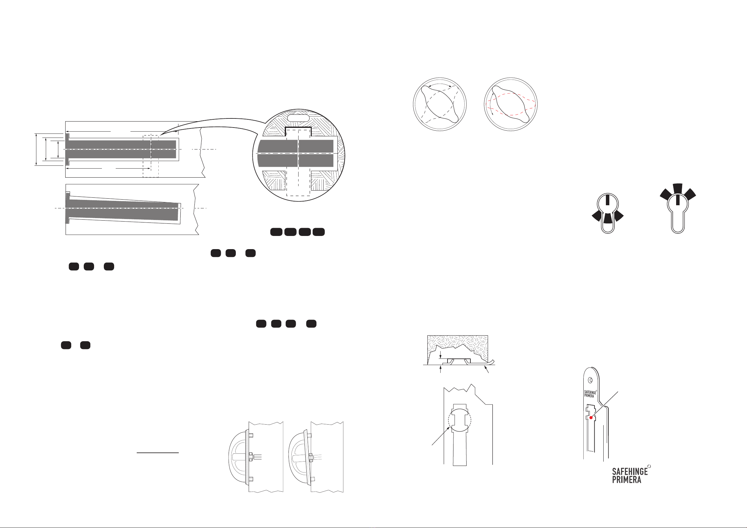
4) Connuing with the template, mark out and neatly drill for the installaon of the locking cylinder ensuring
that the hole is in horizontal alignment. Do not remove more material than is absolutely necessary. Please
ensure sufficient clearance for the back of the single Euro cylinder on models 46 , 56 , 66 & 76 as shown
in figure 1A.
5) Models 86 & 96 require a through hole for the key-key cylinder. Locks with a PR2, PR3 & PR3S prefix
are supplied with an important Secondary Barricade Override safety feature. They must be configured to
ensure nursing staff can gain access to the spindle concealed under the external escutcheon plate. This is
achieved by removal of the an-tamper screw(s) and moving the slider on the escutcheon plate to access the
spindle. Please refer to page 4 for specific informaon on the installaon of this model.
6) Aer following the specific door preparaon guidelines for this model detailed overleaf, please install the
remainder of the ironmongery according to the exploded view and, where Turn/Pull PR4-728-TP is supplied,
in the following order:
A) With the lock inserted (not screwed) in to the morse hole,
offer the round Turn/Pull and 8mm spindle on to the door. The
spindle should go in to the lock follower and allow the Turn to
sit flat against the surface of the door without force. If the Turn
does not sit freely against the surface of the door then the lock
is out of alignment in the morse which should be adjusted
accordingly. Important: If force is used to pull the Turn/Pull
back to the door this will lead to binding, difficult operaon and
possibly premature failure.
B) Cut the 2 x M5 Torx Pin machine Screws to the correct length to ensure sufficient penetraon in to the
Turn/Pull screw ports. If the screws are cut too long the Turn/Pull will not pull firmly back against the surface of
the door resulng in a ligature risk! Secure the Turn/Pull on to the door fastening the screws through the
Twin-Tech escutcheon assembly.
Take care not to over-ghten the fixing screws!
IMPORTANT: When installed correctly the
Turn/Pull should not pass through the horizontal
posion.
C) Install the locking cylinder using the screw
provided again ensuring horizontal alignment. Do not over ghten the cylinder retaining screw as this will
restrict the movement of the key and, in extreme cases can cause the cylinder to collapse. We recommend
that final adjustment is undertaken by hand. Check that the key turns freely and will throw and withdraw the
lock bolt. Important: With the Turn/Pull held rigid the key should withdraw the bolt.
WARNING: This lock should only be used with
cylinders where the cam comes to rest as shown at
Fig ‘A’ when the key is removed.
If using mul-posioned cam cylinders it is
essenal that the cam is posioned accordingly.
Without this the emergency override feature may
not work which could cause damage to the lock.
D) Secure the lock in the morse hole with the an-tamper screws provided and aach face-plate.
Reconfirm that the Turn/Pull and key sll operate the lock freely.
E) According to the exploded view, align all remaining fings and fasten to door using the an-tamper screws
provided. All plates should be secured flat to the surface of the door to prevent ligature risk! Shorter 5/8ths
screws are provided in the fixing pack for circumstances where the 1” screws clash with the lockcase.
F) Finally, mark out and install the strike plate. To adjust the roller catch please refer to magnified view on
page 1. With the door in the closed posion, operate the lock to ensure that the bolt travels freely between
the locked and unlocked posions.
C
L
C
L
14
110
1825 



83
Backset
Clearance required for
back of cylinder on locksets.
( 46 , 56 , 66 , 76 )
For further guidance please contact our Technical Help Line on:
0044 (0) 1253 508643
Fig.1 Fig.6 Fig.7
Fig.4 Fig.5
Fig. 2
Fig.1a

B

A
Posion of the cam when key removed.
IMPORTANT: The angle of the tabs
on the strike plate are factory set.
Under no circumstances should
these be adjusted. Doing so could
cause a lock-out!
IMPORTANT: In the interests of safety, when installing the strike plate in
the frame of the door drill a 19mm
Ø
hole to a depth no greater than
5.5mm from the face of the frame. This will ideally allow the the tabs on
the strike plate to rest against the base of the hole as shown in Fig 8.
Fig.9
Fig.8
5.5mm Maximum Frame of the door from above.
19mm
Ø
IMPORTANT: If the strike plate included in this kit does not carry the logo it is not a genuine part.
Fing an unbranded strike plate will invalidate the warranty of the lock. In such circumstances please refer to
your supplier.

Other Primera Door Lock manuals

Primera 3S-96-731C TWIN-TECH User manual

Primera

Primera 3S-96-731C TWIN-TECH User manual

Primera 1-46-729A Assembly instructions

Primera

Primera 1-46-729A Assembly instructions

Primera 1-46-730C Assembly instructions

Primera

Primera 1-46-730C Assembly instructions

Primera 3S- 96-729A TWIN-TECH User manual

Primera

Primera 3S- 96-729A TWIN-TECH User manual

Primera 1-46-729C Assembly instructions

Primera

Primera 1-46-729C Assembly instructions

Primera 3S-56-731C TWIN-TECH User manual

Primera

Primera 3S-56-731C TWIN-TECH User manual

Primera 3S-46-731C TWIN-TECH User manual

Primera

Primera 3S-46-731C TWIN-TECH User manual

Primera 3S-56 -729A TWIN-TECH User manual

Primera

Primera 3S-56 -729A TWIN-TECH User manual

Primera 1-56-731C Assembly instructions

Primera

Primera 1-56-731C Assembly instructions

Primera TWIN-TECH 3S-56-732H Assembly instructions

Primera

Primera TWIN-TECH 3S-56-732H Assembly instructions

Primera 3S-96-731A User manual

Primera

Primera 3S-96-731A User manual

Primera 1-56-731A Assembly instructions

Primera

Primera 1-56-731A Assembly instructions

Popular Door Lock manuals by other brands

WSS ATELIER F/R Assembly instruction

WSS

WSS ATELIER F/R Assembly instruction

NEAR 5050 user manual

NEAR

NEAR 5050 user manual

SCOOP Pullbloc 3.1 Assembly instruction

SCOOP

SCOOP Pullbloc 3.1 Assembly instruction

Gainsborough Austral Lock Virtus Two Point Hinged Door Mortice... installation guide

Gainsborough

Gainsborough Austral Lock Virtus Two Point Hinged Door Mortice... installation guide

Assa Abloy SARGENT 10X Series installation instructions

Assa Abloy

Assa Abloy SARGENT 10X Series installation instructions

Corbin Russwin Access 700 TCPAC1 Series installation instructions

Corbin Russwin

Corbin Russwin Access 700 TCPAC1 Series installation instructions

AXCEZE AX-M300 quick start guide

AXCEZE

AXCEZE AX-M300 quick start guide

Kwikset WEISER Tavaris 800TVH LIP 26 SMT installation guide

Kwikset

Kwikset WEISER Tavaris 800TVH LIP 26 SMT installation guide

GEZE SecuLogic RWS TZ 300 Installation and Commissioning Instructions with Wiring Diagram

GEZE

GEZE SecuLogic RWS TZ 300 Installation and Commissioning Instructions with Wiring Diagram

Assa Abloy Corbin Russwin ED5800 Series installation instructions

Assa Abloy

Assa Abloy Corbin Russwin ED5800 Series installation instructions

Amplicom RingFlash 250 operating instructions

Amplicom

Amplicom RingFlash 250 operating instructions

Philips EasyKey 7100DS user manual

Philips

Philips EasyKey 7100DS user manual

SDC SK-82 installation instructions

SDC

SDC SK-82 installation instructions

Salto LC1K Series manual

Salto

Salto LC1K Series manual

BURG-WACHTER SET 5011 PINCODE Assembly and user's manual

BURG-WACHTER

BURG-WACHTER SET 5011 PINCODE Assembly and user's manual

Yale Real Living Installation and programming instructions

Yale

Yale Real Living Installation and programming instructions

SDC Excel E1200 Series installation instructions

SDC

SDC Excel E1200 Series installation instructions

FUHR multitronic 881 Installation, operation and maintenance instructions

FUHR

FUHR multitronic 881 Installation, operation and maintenance instructions

manuals.online logo
manuals.online logoBrands
  • About & Mission
  • Contact us
  • Privacy Policy
  • Terms and Conditions

Copyright 2025 Manuals.Online. All Rights Reserved.